
Subscribe to Our Youtube Channel
Related Manuals for ERL F-PRO 116


Summary of Contents for ERL F-PRO 116
- Page 1 F-PRO Non-Directional Multifunction & SEF Protection Relay Model 116 User Manual Version 1.0 Rev 0...
-
Page 3: Preface
While all information presented is believed to be reliable and in accordance with accepted engineering practices, ERL makes no warranties as to the completeness of the information. All trademarks used in association with L-PRO, T-PRO, F-PRO, B-PRO, S-PRO, TESLA, iTMU, TESLA Control Panel, Relay Control Panel, RecordGraph, RecordBase and ProLogic are trademarks of ERLPhase Power Technologies Ltd. -
Page 4: Using This Guide
Using This Guide This User Manual describes the installation and operation of the F-PRO Multifunction Protection Relay. It is intended to support the first time user and clarify the details of the equipment. The manual uses a number of conventions to denote special information: Example Describes Choose the Control Panel submenu in the... -
Page 5: Table Of Contents
Table of Contents Preface ……………………… ……………………………………….……..….. ……………… Contact Information...…………………………..……………………………………… Using this Guide ………………………………………………………………………….… Table of Contents ……………………….…………………………………...…………… Acronyms …………………………………………………………………………….……….. Version Compatibility …………………………………………….…………………….. PC System Requirements and Software Installation …………………….. Overview 1.1 Introduction …………………………………..……….……….……..………….. 1.2 Front View ………………………………………..…………………..……..……. 1.3 Rear View ……………………………………………………….……………..………. 1.4 Model Options/Ordering ……….………………………………..……….. - Page 6 Data Communications 5.1 Introduction………………………………………………………………………….. 5.2 SCADA Protocol……………………………………………………………………… Settings and Analysis Software 6.1 Introduction …………………..………………………………………………..…… 6.2 Offliner Setting Software ………………………………………………………. 6.3 Offliner Features ……………….………………………………………………….. 6.4 Offliner Keyboard Shortcuts …………….……………………………………. 6.5 Handling Backward Compatibility ………..…………………………….…. 6.6 Main Branches from the Tree View ………….………………………..…. 7.
-
Page 7: Acronyms
Acronyms - Current Transformer - Data Communication Equipment - Human Machine Interface - International Electro-technical Commission - Intelligent Electronic Device - Light-emitting Diode - Liquid Crystal Display - Left Hand Side - Right Hand Side - Setting Group - User Interface E00116R01.00 F-PRO116 User Manual... -
Page 8: Version Compatibility
Offliner Settings are backward compatible with all earlier versions of setting files. F-PRO Firmware/Software Compatibility Guide Compatible Offliner Setting F-PRO Firmware Version Settings V1.0 V0.07(post v2.6) Please contact ERL Technical support for complete Revision History. F-PRO116 User Manual E00116R01.00... -
Page 9: Pc System Requirements And Software Installation
Microsoft Windows 7 Microsoft Windows 10 ERL softwares requires a minimum of Windows 7 OS (Hyper Terminal /Offliner will not work on earlier versions of Windows). Software Installation All required software for user interface, setting are available directly from the ERL website: http://www.easunreyrolle.com/product.php?id=1096. - Page 10 Anti-virus/Anti-spyware Software If an antivirus/anti-spyware software on user local system identifies any of the ERL & ERLPhase applications as a “potential threat”, it will be necessary to configure user antivirus/anti-software to classify it as “safe” for its proper operation. Please refer the appropriate antivirus / anti- spyware software documentation to determine the relevant procedure.
-
Page 11: Overview
1 Overview 1.1 Introduction The F-PRO is a microcontroller-based relay providing comprehensive Overcurrent / Earth Fault Protection, Sensitive Earth Fault / Restricted Earth Fault, Auto Reclosing, Circuit Breaker Failure, Broken conductor, Thermal Overload, Negative Sequence Overcurrent, Inrush Restraint, Trip Circuit Supervision, Metering, Breaker Monitoring functions suitable for distribution applications. - Page 12 Figure 1.1: F-PRO Relay Function Line Diagram F-PRO116 User Manual E00116R01.00...
-
Page 13: Front View
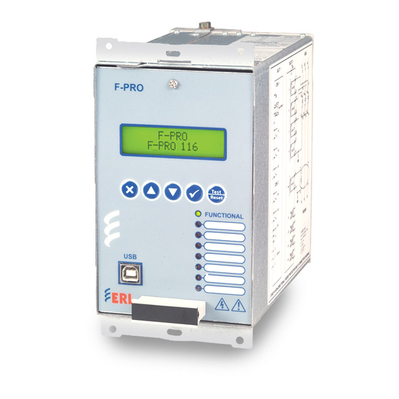
1.2 Front View Enter to menu & sub-menu Navigation controls allow for an easy experience through settings, change, service and view menus. Back/close button Programmable target LED’s provide tripping information to expedite response to systems events. Front panel USB port provides easy and fast access to settings and set up Handle to draw out the... -
Page 14: Rear View
1.3 Rear View Case Grounding RS-485 terminals for SCADA communication (MODBUS and IEC103) Figure 1.3: F-PRO Rear View F-PRO116 User Manual E00116R01.00... -
Page 15: Model Options/Ordering
F-PRO is provided with terminal blocks for up to 5 AC currents (3 AC Current Inputs Phase Current, 1 Neutral and 1 SEF). 1A and 5A are seperate terminals, 1A or 5A CT Secondary is Site Selectable. To refer the complete schematic circuits; see “AC Schematic Drawing”... - Page 16 Figure 1.4: Ordering Template F-PRO116 User Manual E00116R01.00...
-
Page 17: Setup And Communication
2 Setup and Communications 2.1 Introduction This chapter discusses setting up and communicating with the relay including the following: Power supply Communicating with the relay using a direct serial link Using Hyper Terminal to access the relay’s user interface 2.2 Power Supply A wide range power supply is standard. -
Page 18: Communicating With The F-Pro Relay
2.4 Communicating with the F-PRO Relay Connect to the IED for access its user interface and supervisory control and data acquisition (SCADA) services by: • Front USB 2.0 interface (user interface and maintenance) Rear panel serial link (RS485 serial link ) The relay has a front panel USB port (COM 1) and 1 rear RS485 Port (COM 2) to provide direct access to IEC103/Modbus services. - Page 19 To create a USB link between the relay and the computer, connect the PC to the front USB port of the F-PRO. The STM32 VCP Driver needs to be installed in computer as follows: STM32 VCP can be downloaded from ERL website. http://www.easunreyrolle.com/product.php?id=1096 Then go the Device Manager to check the port detect.
- Page 20 2.8 Accessing the Relay’s SCADA Services The relay supports IEC 60870-5-103 slave and Modbus slave SCADA protocols as a standard feature on all F-PRO series relays. The Modbus implementation supports both Remote Terminal Unit (RTU) binary and ASCII modes and is available through a direct RS485 serial link. The relay Port 2 is dedicated for use with Modbus slave, IED 60870-5-103 slave protocols.
-
Page 21: Communication Port Details
2.9 Communication Port Details Table 2.1: Communication Port Details Location Port Function Front Panel COM 1 USB-B receptacle, High speed USB 2.0 interface Used for user interface access Default fixed baud rate 115200 N 8 1 (no parity, 8 data bits, 1 stop bit). Rear Panel COM 2 RS-485. -
Page 22: Using The Ied (Getting Started)
3 Using the IED (Getting Started) 3.1 Introduction This section provides information on the start-up sequence and ways to interface with the F-PRO relay. Descriptions of the Front Panel Display, Terminal Mode and Metering Data are provided. 3.2 Start-up Sequence When the power supply is connected, the following initialization initializing sequence takes place: •... -
Page 23: Front Panel Display
3.4 Front Panel Display The front panel display is the fastest and easiest way of getting information from the relay. Navigation controls allow for an easy experience through settings, maintenance, service and view menus Programmable target LEDs provide tripping information to expedite Response to systems events. - Page 24 LED Indications Table 3.1: Description of LED Indications Indicates the relay is functional. When the Relay Functional green LED 1 LED comes on, the rear Relay Inoperative contact opens and the protective functions become functional. Programmable for any Protection functions, ProLogic and External LED 2 to 8 Inputs.
- Page 25 Display The basic menu structure for navigation of the LCD screen is given below: Table 3.3: Navigation of the LCD Screen Main Screen View / Change / Service : Choice Menu Enter Password to go to Change / Service Menu Main Menu (V,C,S) Configuration...
- Page 26 Table 3.3: Navigation of the LCD Screen Pickup Delay (V,C,S) Inrush Blocking (V,C,S) Fn. 51 (V,C,S) Function (V,C,S) Pickup Current (V,C,S) Curve (V,C,S) (V,C,S) Pick Up DTL Delay (V,C,S) (V,C,S) Reset Delay Reset DTL Delay (V,C,S) Constant A (V,C,S) Constant B (V,C,S) Constant p (V,C,S)
- Page 27 Table 3.3: Navigation of the LCD Screen Constant A (V,C,S) Constant B (V,C,S) Constant p (V,C,S) Constant TR (V,C,S) Inrush Blocking (V,C,S) (V,C,S) Fn. 64/50SEF-1 (V,C,S) Function (V,C,S) Pickup Current (V,C,S Pickup Delay (V,C,S) Inrush Blocking (V,C,S) Fn. 64/50SEF-2 (V,C,S) Function (V,C,S) Pickup Current...
- Page 28 Pickup Delay (V,C,S) Fn. 46/51 (V,C,S) Function (V,C,S) Pickup Current (V,C,S) (V,C,S) Curve (V,C,S) Pick Up DTL Delay (V,C,S) Reset Delay (V,C,S) Constant A (V,C,S) Constant B (V,C,S) Constant p (V,C,S) Constant TR (V,C,S) Thermal Overload (V,C,S) Fn. 49 (V,C,S) Function (V,C,S) Therm.
- Page 29 Name (V,C,S) Function (V,C,S) Name (V,C,S) Drop-Off Delay (V,C,S) Inrush Detection (V,C,S) Fn. 81HBL2 (V,C,S) Function (V,C,S) Cross Blocking (V,C,S) Pickup I2nd (V,C,S) Auto Reclose (V,C,S) Fn. 79 (V,C,S) (V,C,S) Function Number of Shots (V,C,S) (V,C,S) 1st Reclose--T1 (V,C,S) 2nd Reclose--T2 (V,C,S) 3rd Reclose--T3 4th Reclose--T4...
- Page 30 Thermal State (V,C,S) (V,C,S) Digital EI Status (V,C,S) EI1- El 1 (V,C,S) EI2- EI 2 (V,C,S) EI3- EI 3 (V,C,S) EI4- EI 4 (V,C,S) DO Status (V,C,S) RL1-RL 1 (V,C,S) RL2-RL 2 (V,C,S) RL3-RL 3 (V,C,S) RL4-RL 4 (V,C,S) RL5-RL 5 (V,C,S) RL6-RL 6 (V,C,S)
- Page 31 Communication (V,C,S) (V,C,S) USB(Serial) Host: Serial VCP (V,C,S) RS-485(CON2) (V,C,S) Protocol (V,C,S) Modbus-RTU/ASCII (V,C,S) (V,C,S) Relay Address (V,C,S) Baud Rate Parity (V,C,S) Protocol (V,C,S) IEC-103 Slave (V,C,S) Relay Address (V,C,S) Erase Records (C,S) Erase Event Rec (C,S) Erase Fault Rec (C,S) Password Settings (V,C,S)
- Page 32 Calibrate IG? Calibrate ISEF? Test Mode Test Mode Selection OUTPUT Class 2 Update (V,C,S) Measurand Max Range (V,C,S) Baud Rate (V,C,S) Parity (V,C,S) Unit Identifications (V,C,S) Product Version (V,C,S) Serial Number (V,C,S) Unit ID (V,C,S) (V,C,S) Firmware Ver. Settings Date (V,C,S) (V,C,S) Settings Ver.
- Page 33 To login into the LCD menu structure, follow these steps: 2013Feb24 F-PRO 12:17 Bay Name O-10122 Figure 3.2: Main Screen In the Main Screen, Press Enter Key. View Change Figure 3.3: View / Change / Service: Choice Menu In the View / Change / Service: Choose Menu screen, choose desired access level, and Press Enter key.
- Page 34 3.5 Hyper Terminal HyperTerminal is used for all user interfaces with IED online. A short description of the Hyper Terminal configuration to connect to a relay is given here. Follow software files needs to be installed before connecting USB link to the relay: Execute "Hyperterminal.exe"...
- Page 35 Enter the desired values (1 or 2 or 3 or 4) to select the appropriate options. 1)Enter 1 for loading configuration to the relay. 2)Enter 2 for Collect/Erase Event Log data in the relay. 3)Enter 3 for Collect/ Erase the stored Fault Log Data in the relay. 4)Enter 4 to get the configuration file from the relay.
- Page 36 Setting Group and Setting File Selection E00116R01.00 F-PRO116 User Manual 3-15...
- Page 37 After the configuration file got successfully loaded the hyper terminal shows the text “configuration File Successfully loaded”. Configuration File Successfully Loaded 2) Get/Erase Event Log In the main menu, after enter the value 2 the below mentioned options will appear ...
- Page 38 Get EventLog E00116R01.00 F-PRO116 User Manual 3-17...
- Page 39 To save the EventLog file as a text file 1)Select Capture Text under the Transfer Menu 2)Select the Local path Event Erase 3-18 F-PRO116 User Manual E00116R01.00...
- Page 40 3) Get/Erase Fault Log In the main menu, after enter the value 2 the below mentioned options will appear Enter A to get Fault Log data from the relay Enter B to get fault Log data from the relay Erase Fault Log E00116R01.00 F-PRO116 User Manual...
- Page 41 4) Get Configuration File 3-20 F-PRO116 User Manual E00116R01.00...
-
Page 42: Protection Functions And Specifications
4 Protection Functions and Specifications 4.1 Protection Functions Introduction This section describes the equations and algorithms that are define the F-PRO216 relay Protection functions. The available functions are 50-1, 50-2, 51, 50G-1, 50G-2,51G, 64/50SEF-1, 64/50SEF-2, 51SEF, 46/50, 46/51, 74TCS-1, 74TCS-2, 49, 50BF, 46BC, 81HBL2, I^2t, 79. These functions are explained below with setting ranges and logic diagrams. - Page 43 50 – Overcurrent Logic diagram Functional Block Via External Input Function Enable 50 Operated I Rms > 50 I Pickup Inrush Block Figure 4.1: Logic Diagram of 50 Function Table 4.1 50 - Phase Overcurrent Settings (No. of Stages – 2) Setting Description Range Function Activation...
- Page 44 51 - IDMTL Overcurrent Logic Diagram Functional Block Via External Input Function Enable 51 Operated I Rms > 51 I Pickup Inrush Block Figure 4.2: Logic Diagram of 51 Function Table 4.3: 51 (IDMTL) Phase Overcurrent Settings (No. of Stages – 1) Setting Description Range Function Activation...
- Page 45 50G/51G Measured Neutral Overcurrent Measured Neutral Overcurrent Protection is provided for detection & clearance of Ground faults. Though Phase Overcurrent can also detect Line to Ground faults, for high resistance Ground faults, Neutral Overcurrent protection will be more sensitive than Phase Overcurrent Protection.
- Page 46 50G - Neutral Overcurrent Logic diagram Functional Block Via External Input Function Enable 50 G Operated IG > 50G Pickup Inrush Block Figure 4.3: Logic Diagram of 50G Function 51G – IDMTL Neutral Overcurrent Logic diagram Functional Block Via External Input Function Enable 51G Operated...
- Page 47 Table 4.7: 51G (IDMTL) Neutral Overcurrent Settings (No. of Stages – 1) Setting Description Range Function Activation Enable/disable 0.05 to 10 (1 A) Pickup 0.25 to 50 (5 A) Curve Type For details see Table 4.2 “IEC and IEEE Curves” 0.01 to 10.00 Pickup DTL Delay 0.00 to 999.99 seconds if chosen for DTL characteristics...
- Page 48 Once an earth fault occurs in the high resistance grounding system, an alarm needs to be generated and the fault needs to be traced. For this a reliable protection which detects earth faults even when the fault current is very low is necessary. Undetected earth faults in this system are dangerous as a second earth fault in another phase may result in a short- circuit.
- Page 49 64/51 – IDMTL SEF Protection Logic diagram Figure 4.6: Logic Diagram of 64/51 Function Table 4.9 64/51SEF - Inverse Time Sensitive /Restricted Earth Fault Setting Description Range Function Activation Enable/Disable 0.005 to 1.000 (1 A) / 0.025 to 5.000 (5 A) Pickup ISEF Curve Type For details see Table 4.2 “IEC and IEEE Curves”...
- Page 50 46-50/51 Negative Sequence Overcurrent Negative Sequence Overcurrent provides protection for any unbalanced loading which may occur during phase to phase faults and also in detecting asymmetrical faults with magnitude lower than the maximum load current. Function 46-50, 46-51 is similar to 50 or 51 except derived negative sequence current is utilized to drive the algorithm.
- Page 51 Table 4.11 46-51 (IDMTL) Negative Sequence Overcurrent Settings (No. of Stages -1) Setting Description Range Function Activation Enable/Disable 0.05 to 0.95 (1 A) / 0.25 to 4.75 (5 A) Pickup Curve Type For details see Table 4.2 “IEC and IEEE Curves” 0.01 to 10.00 Pickup DTL Delay 0.00 to 999.99 seconds if chosen for DTL characteristics...
- Page 52 Where, = Operating time in minutes = Thermal time constant in minutes = Natural log = Steady state relay current prior to overload = Basic current = Effective relay current Basic current IB is full load current of the protected feeder. Constant k is a multiplying factor resulting in the 49 Thermal OL setting of the relay Iθ...
- Page 53 Where θ = Thermal state in percentage at time t θ = Final thermal state before disconnection of feeder I = Effective relay current. = Thermal overload setting θ = Thermal time constant in minutes. The final thermal state θ for any steady state value of input current can be predicted using the following formula.
- Page 54 50BF Breaker Failure There are two sets of breaker failure protection functions. W hen breaker failure is initiated by an external trip or other internal logic (user-settable through the output matrix) and the breaker current still exists, two timers (T1 and T2 – user-settable) are started. After these timers are timed out, and if the current still exists indicating a breaker failure, the output of this function is set high.
- Page 55 46BC Broken Conductor The Broken Conductor (46BC) function can detect unbalanced series or open circuit faults (referred to as series faults from here on). Series faults can arise from broken conductors or jumpers, misoperation of single phase switchgear and the operation of series fuses. Series faults do not cause an increase in phase currents in the system and thus are not easily detectable by standard overcurrent relays.
- Page 56 74TCS Trip Circuit 74TCS function detects trip circuit failure when 74 TCS asserts and followed by Supervision the drop-off timer unit operation. The drop-off timer delay can be set using 74TCS DTL setting value. On expiry of the drop-off delay, the final operate output of the function is issued.
- Page 57 81HBL2 – Inrush Block Logic diagram Figure 4.13: Logic Diagram of 81HBL2 Functions Table 4.16: 81HBL2 Inrush Block Setting Description Range 81HBL2 Enable/Disable Cross Blocking Enable/Disable Percentage of second harmonic 5 to 50 % current I 2nd 79Reclose F-PRO includes a four shot recloser. After four reclose attempts, the recloser is locked out. The lockout is cleared once the feeder returns to normal by manual operation, meaning that the feeder has been on with a load greater than the low set setting for a certain amount of time.
- Page 58 79 – Auto reclose Logic diagram Figure 4.14: Logic Diagram of 79 Functions E00116R01.00 F-PRO116 User Manual 4-17...
- Page 59 Table 4.17: 79 Recloser Setting Description Range 79 Recloser Enable/disable Number of Shots 1 to 4 First Reclose (T1) 0.10 to 999.99 seconds Second Reclose (T2) 1.00 to 999.99 seconds Third Reclose (T3) 1.00 to 999.99 seconds Fourth Reclose (T4) 1.00 to 999.99 seconds Close Time (Tp) 0.01 to 1.00 seconds...
- Page 60 ProLogic ProLogic is used to create an output based on qualified multiple inputs. 5 User Programmable ProLogic control statements can be utilized to create custom logic which may be mapped to output contacts. User can define or name the function being created and set a pickup and dropout delay. Each ProLogic statement can be used with internal relay functions and external inputs (up to 5 possible inputs) to create the logic output by using Boolean logics such as AND, OR, NAND, NOR, XOR, EX0-OR and LATCH.
- Page 61 Group Change Control Statement The F-PRO relay has two setting groups (SG1 to SG2). The user can change all relay setting parameters except the physical connections such as input, in each setting group. Setting group changes can also be performed by using any one of the 4 available Digital Inputs per setting group or through relay display interface.
-
Page 62: Logging Functions
Automatic Settings Change The relay configuration changes during a relay-initiated setting change, but the protection function operations are not disrupted. Since the relay setting file does not change, the interface controller uses the new setting group supplementary setting information at the same time as the protection controller switches to the new setting group. - Page 63 Table 4.20: Fault Log Fault Type Fault Quantities - Phase Indication (digital indication of A/B/C phases) 50-1 - Main I1A/I1B/I1C/IN Phasors - Phase Indication (digital indication of A/B/C phases) 50-2 - Main I1A/I1B/I1C/IN Phasors - Phase Indication (digital indication of A/B/C phases) 51-1 - Main I1A/I1B/I1C/IN Phasors Table 4.21: Fault Log...
-
Page 64: Data Communications
5 Data Communications 5.1 Introduction The SCADA protocol deals with the Modbus and IEC 60870-5-103 protocols. The SCADA configuration and settings are described. The parameters for SCADA communications are defined using F-PRO Offliner software. Finally, details on how to monitor SCADA communications are given for maintenance and troubleshooting of the relay. - Page 65 Offliner SCADA Details on using the Offliner software are available in “To Install Software on Configuration the Computer” on page -viii. Details on downloading a completed settings file to the relay are available in “Sending a New Setting File to the Relay” on page 6-7.
-
Page 66: Settings And Analysis Software
6 Settings and Analysis Software 6.1 Introduction This section describes the supporting software used to set the relay parameters. The offliner software tool is used for these purposes: F-PRO Offliner is used to configure all of the protection and system parameter variables on the IED. Setting files are created locally on a personal computer with the Offliner software and then are sent to the IED through Hyper Terminal (see “HyperTerminal”... -
Page 67: Offliner Features
Figure 6.1: Protection Summary 6.3 Offliner Features The Offliner software includes the following menu and system tool bar. Setting Area Setting Tree Figure 6.2: Offliner Features F-PRO116 User Manual E00116R01.00... - Page 68 Table 6.1: Windows Menu Windows Menu Sub Menu Comment Restores active window to Document Restore previous size Menu (Icon) Move Allows user to move active window Size Allows user to resize active window Makes the active window as Minimize small as possible Makes the active window as Maximize large as possible...
- Page 69 Table 6.1: Windows Menu Edit Paste Insert clipboard contents Copy Graph Copy the graph for the active screen to the clipboard Copy Setting Group Copy values from one Setting Group to another Options Print settings for only enabled Tools Settings Summary sheet Window Cascade Cascades all open windows...
-
Page 70: Offliner Keyboard Shortcuts
6.4 Offliner Keyboard Shortcuts The following table lists the keyboard shortcuts that Offliner provides. Table 6.2: Keyboard Shortcuts Ctrl+N Opens up a default setting file of the most recent setting version Ctrl+O Open an existing setting file Ctrl+S Saves the active setting file Ctrl+Z Undo Ctrl+X... - Page 71 Figure 6.3: Converting Setting Files F-PRO216 User Manual E00011R01.40...
- Page 72 The sample file is “v1 sample.fps”. The sample file contains default values of an older settings version. For a new installation these sample files are placed in the default directory C:\Program Files\ERL\F-PRO Offliner Settings or user can choose the path during the Offliner software installation.
-
Page 73: Main Branches From The Tree View
6.6 Main Branches from the Tree View Identification This section will describe the tree view, which provides access to the various setting screens. This section will not describe individual settings, but will provide a general description of where to find the individual settings. For a detailed description of the individual settings see Chapter 3. LHS Menu Tree RHS –... - Page 74 In the LHS Menu Tree there are a series of menu headings that may have sub menus associated with them. Clicking on an item in the left hand side tree view will display its corresponding menu in the RHS view. Similarly, the user can use the arrow keys to scroll through the menu tree. The first screen presents all the menu items in the left menu tree.
- Page 75 External Inputs Figure 6.5: External Inputs The External Inputs screen allows user to define meaningful names for four external inputs. Table 6.4: External Input Names 1 to 4 User-defined Output Contacts Figure 6.6: Output Contacts The Output Contact Names screen allows user to define meaningful names to the 6 output contacts. Table 6.5: Output Contact Names Outputs 1 to 6 User-defined...
- Page 76 Setting Groups Figure 6.7: Setting Groups The relay has two setting groups (1 to 2). User can change all relay setting parameters except the physical connections such as input or output parameters in each setting group. Use any one of the 4 available Group change inputs per group. Logic Statements per setting group to perform Setting Group changes.
- Page 77 The System Parameters screen allows user to define CT Secondary Ratio for the respective bays Table 6.8: System Parameters CT Configuration Phase CT Sec. Current 1A/ 5A Neutral CT Sec. Current 1A/ 5A SEF CT Sec. Current 1A/ 5A Phase CT ratio 1.0 to 30000.0 Neutral CT ratio 1.0 to 30000.0...
- Page 78 SCADA Summary Figure 6.10 SCADA summary The relay address can be set from 1 to 247 for serial mode of communication either Modbus RTU / Modbus ASCII and can be set from 0 to 254 for IEC103 Slave and also possible to set baud rate &...
- Page 79 Setting Groups Figure 6.11: Setting Groups Comments The relay has two setting groups (1 to 2). User can change all relay setting parameters except the physical connections such as input or output parameters in each setting group. Use any one of the 2 available Group change inputs per group. Logic Statements per setting group to perform Setting Group changes.
- Page 80 Protection Functions For detailed descriptions of the protection functions see “Protection Functions and Specifications” on page 4-1. Figure 6.12: Protection Functions ProLogic Figure 6.13: ProLogic E00116R01.00 F-PRO116 User Manual 6-15...
- Page 81 ProLogic is used to create an output based on qualified multiple inputs. Twenty User Programmable ProLogic control statements can be utilized create custom logic and operate output contacts. User can define or name the function being created and set a pickup and dropout delay. Each ProLogic statement can be used with internal relay functions and external inputs (up to 5 possible inputs) to create the logic output by using Boolean logics such as AND/ OR, NAND/NOR, XOR/NXOR and LATCH.
- Page 82 Settings Summary Figure6.15: Settings Summary Select Settings Summary to view and print the relay settings in text form. For details see “IED Settings and Ranges” in Appendix B. Print the entire Settings Summary by selecting File>Print Summary. E00116R01.00 F-PRO116 User Manual 6-17...
-
Page 83: Acceptance/Peripheral Test Guide
7.2 Acceptance Testing ERL relays are fully tested before leaving the factory. A visual inspection of the relay and its packaging is recommended on receipt to ensure the relay was not damaged during shipping. - Page 84 Calibration The relay is calibrated before it leaves the factory, but if component changes are made within the relay, the user may need to do a re-calibration. Testing the External Inputs External Inputs are polarity sensitive! To test the external inputs connect through LCD display. This screen displays the status of the Input and Output Contacts.
-
Page 85: Installation
Installation 8.1 Introduction This section details the installation of the F –PRO relay. The section covers the physical mounting, AC and DC wiring and the Communication wiring. 8.2 Physical Mounting The relay is 177 mm height and 175mm depth (Approximately). The standard Standard E4 relay is designed for a 103.5 mm width. -
Page 86: Appendix A Ied Specifications
Appendix A IED Specifications F-PRO116 Specifications Item Quantity/Specs Note General: Nominal Frequency 50 or 60 Hz Including output relay operation Operating Time Less than 30 ms Settings and records are stored in non- Records are stored in a circular Memory volatile memory buffer 20 to 60Vdc... - Page 87 F-PRO 116 Specifications Input & Output: Nominal Current In = 1 Amp or 5 Amps Analog Current Inputs 4x In = 4 Amps or 20 Amps 1 set of 3-phase current inputs 100 Amps for 1 second Full Scale/Continuous Maximum (3 current channels) ,1 current <0.1 VA @ 1 Amp...
- Page 88 F-PRO 116 Specifications Physical: Weight 2.0 Kg E4 case:177mm High x 103.5 mm Wide x Overall Dimensions 175mm Depth Cutout Dimensions – Flush E4 case : 159mm High x 97mm Wide Mount Overall F-PRO Accuracies ±2.5% of inputs from 0.1 to 1.0 x nominal current (I n ) Current ±1.0% of inputs from 1.0 to 4.0 x nominal current (In)
- Page 89 Detailed Environmental Tests Standard Description of the Test Test Points Test Level IEC 60255-26:2013 Enclosure Air +/- 8 kV Electrostatic Discharge Cl.No.7.2.3 Enclosure contact +/- 6 kV Radiated interference IEC 60255-26:2013 10 v/m : 80-1000 MHz (Electromagnetic Field Enclosure ports Cl.No.7.2.4 : 1.4 GHz - 2.7 GHz Immunity)
- Page 90 A.1 IDMTL Element Operating Time Curves Figure A.1: IDMTL IEC very inverse curve. Figure A.2: IDMTL IEC Standard inverse curve 3. E00116R01.00 F-PRO116 User Manual AppendixA-5...
- Page 91 Figure A.3: IDMTL IEC Standard inverse curve 1. Figure A.4: IDMTL IEC Long inverse curve AppendixA-6 F-PRO116 User Manual E00116R01.00...
- Page 92 Figure A.5: IDMTL IEC Extremely inverse curve. Figure A.6: IDMTL IEEE Moderately inverse curve. E00116R01.00 F-PRO116 User Manual AppendixA-7...
- Page 93 Figure A.7: IDMTL IEEE very inverse curve Figure A.8: IDMTL IEEE Extremely inverse curve. AppendixA-8 F-PRO116 User Manual E00116R01.00...
-
Page 94: Appendix B Ied Settings And Ranges
Appendix B IED Settings and Ranges This topic describes the settings and its ranges of F-PRO116 relay. When a setting has been completed in the F-PRO Offliner software, it can be printed along with the ranges available for these settings. This summary is however, a quick way of having a look at all the settings in a very compact form. - Page 95 F-PRO Settings Summary Setting Group 1 [SG 1] Name Symbol/Value Unit Range Setting Group Names Setting Group 1 SG 1 Setting Group 2 SG 2 Phase CT Sec. current Neutral CT Sec SEF CT Sec Phase CT Ratio 100.0 1 to 30000 Neutral CT Ratio 100.0 1 to 30000...
- Page 96 F-PRO Settings Summary - Setting Group 1 [SG 1] Name Symbol/Value Unit Range 64/50SEF – Instantaneous SEF 64/50SEF – 1 Disabled 0.005 to 2.500(1A) 0.025 to Pickup Isef> 12.500(5A) Pickup Delay 0.00 to 999.99 Inrush Block Enabled 64/50SEF – 1 Disabled 0.005 to 2.500(1A) 0.025 to Pickup Isef>...
- Page 97 F-PRO Settings Summary - Setting Group 1 [SG 1] Name Symbol/Value Unit Range Reset Delay ANSI Decay Reset DTL Delay 0.0 to 99.9 0.14 0.02 Reset Delay(TR) 13.5 0.10 to 150.00 49-Thermal overload Disabled Thermal Overload 1.05 0.20 to 2.00 Time Constant 0.50 to 100.00 Neg.
- Page 98 F-PRO Settings Summary - Setting Group 1 [SG 1] Name Symbol/Value Unit Range 81HBL2 - Inrush 81HBL2 Disabled Cross Blocking Enabled Pickup I2nd> 5 to 50 79 - Recloser Disabled Number Of Shots 1 to 4 First Reclose - T1 0.10 to 999.99 Second Reclose - T2 1.00 to 999.99...
- Page 99 F-PRO Settings Summary - Setting Group 1 [SG 1] Name Symbol/Value Unit Range PL 3[ProLogic 3] ProLogic 2 Disabled Pickup Delay-Tp 0.00 to 999.00 Dropout Delay-Td 0.00 to 999.00 Operator 1 Input A <Unused = 0> Operator 2 Input B <Unused = 0>...
- Page 100 F-PRO Settings Summary - Setting Group 1 [SG 1] Name Symbol/Value Unit Range ResetTime Reset Type[RL 2] Self Reset ResetTime Reset Type[RL 3] Self Reset ResetTime Reset Type[RL 4] Self Reset ResetTime Reset Type[RL 5] Self Reset ResetTime Reset Type[RL 6] Self Reset ResetTime Target LED Reset...
- Page 101 Appendix C Hardware Requirements The relay is designed and manufactured with high quality features for a complete feeder protection package. The following information describes the main hardware components of the relay: CPU Board (CPUB): The CPUB has high speed controller which performs the entire relay operation. The CPUB is interfaced to ADCEI, which manages the protection features of the relay.
- Page 102 SMPS & DO BOARD: This board contains SMPS and it provides the power supply for the entire unit. The switching frequency is 132 kHz and it reduces the transformer size with no noticeable impact on EMI, accurate programmable current limit, fully integrated soft-start for minimum start-up stress. The two power supply operating ranges are 20 –...
- Page 103 Appendix D Event Messages F-PRO Event Messages Event Log Message Notes 50-1 : Picked up The possible phase information will be: • A 50-1: Operated • B 50-2 : Picked up • C 50-2 : Operated • AB 51-1 : Picked up •...
- Page 104 F-PRO Event Messages 79 Reclose 79 AR Initiate 79 Block 79 Lockout ProLogic outputs names are ProLogic Name: PLn user- assigned External input names are user- Extern Input Name: EIn assigned Where n = 1-4 New Settings loaded, Active group n. Where n = 1-2 Manual Settings Load request, activate Where n= 1-2...
- Page 105 Appendix E Modbus RTU Communication Protocol F-PRO COM 2 port supports IEC 103 and Modicon Modbus protocols. All metering values available through the terminal user interface are also available via the Modbus protocol. Additionally, the Modbus protocol support the reading of the unit time and time of the readings and provides access to trip, alarm events and also includes fault information.
- Page 106 46/51 Operated 0: OFF 1: ON 64/50SEF-1 Picked up 0: OFF 1: ON 64/50SEF-2 Picked up 0: OFF 1: ON 64/50SEF-1 Operated 0: OFF 1: ON 64/50SEF-2 Operated 0: OFF 1: ON 64/51SEF-1 Picked up 0: OFF 1: ON 64/51SEF-1 Operated 0: OFF 1: ON 49 Picked up...
- Page 107 Relay O/P3 0: OFF 1: ON Relay O/P4 0: OFF 1: ON Relay O/P5 0: OFF 1: ON Relay O/P6 0: OFF 1: ON E00116R01.00 F-PRO116 User Manual Appendix E-3...
- Page 108 In the below table, Scale value should be divided with the metering data obtained from Modbus. Read Holding Registers (Function Code 03) Channel Address Units Scale IA Magnitude 40257 IA Angle 40258 Degrees IB Magnitude 40259 IB Angle 40260 Degrees IC Magnitude 40261 IC Angle...
- Page 109 Read Input Register (Function Code 04) No input registers supported. Response front IED indicates “ILLEGAL FUNCTION.” Force Single Coil (Function Code 05) Only the “hold readings” coil can be forced. When active, this coil locks all coil, input and holding register readings simultaneously at their present values.
- Page 110 Write Multiple Registers (Function Code 16) Channel Address Units Scale F-PRO Clock Time (UTC) – Note: Must write to all the registers in same query 0 – 999 Milliseconds now 40001 Seconds now 40002 0 – 59 Minutes now 40003 0 –...
- Page 111 Get Next Event (Function Code 6, address 40515): Places the next event in the read registers without acknowledging the current event. The current event will reappear in the list when Refresh Event List is used. Size of Current Event (Function Code 3, address 40516): Indicates the number of 16 bit Message registers used to contain the current event.
- Page 112 Sample Event Record Register Value Meaning High Byte Low Byte 40516 0x00 0x14 Event text size = 20 (0x14 hex) 40517 0x32 0x30 ‘2’, ‘0’ 40518 0x31 0x33 ‘1’, ‘3’ 40519 0x53 0x65 ‘S’, ‘e’ 40520 0x70 0x31 ‘p’, ‘1’ 40521 0x32 0x20...
- Page 113 Function Type Description IEC Overcurrent Protection ERL Overcurrent Protection ERL Voltage Protection ERL Frequency Protection ERL Synchronizing Function ERL High Impedance Differential Protection ERL Motor Protection ERL Capacitor Protection IEC Transformer Protection ERL Transformer Protection IEC Generic IEC Global Cause of...
- Page 114 Direction of event Raised Only (RO), Raised / Cleared (RC)or Double Point Travelling, Cleared, Raised or Unknown (DP) Supported Not supported Appendix F-2 F-PRO116 User Manual E00116R01.00...
- Page 115 E00116R01.00 F-PRO116 User Manual Appendix F-3...
- Page 116 Appendix F-4 F-PRO116 User Manual E00116R01.00...
- Page 117 Appendix G Mechanical Drawings G.1 Front View E00116R01.00 F-PRO116 User Manual Appendix G-1...
- Page 118 G.2 Rear View Appendix G-2 F-PRO116 User Manual E00116R01.00...
- Page 119 Appendix H AC Schematic Drawing E00116R01.00 F-PRO116 User Manual Appendix H-1...
- Page 120 Appendix I DC Schematic Drawing E00116R01.00 F-PRO116 User Manual Appendix I-1...
- Page 121 Appendix J Function Logic Diagram E00116R01.00 F-PRO116 User Manual Appendix J-1...
- Page 122 Appendix K Connection Diagram E00116R01.00 F-PRO116 User Manual Appendix K-1...
- Page 123 Appendix-L F-PRO Setting Example Protection, Timers and The relay does not block any protection functions or external inputs I/O Status during the setting save or active group change, but the external output contacts are reset for one cycle. The relay applies the setting parameters, resets all protection functions, resets all timers and continues to process the protection algorithms but does not apply any action to the output contacts for one cycle.
Need help?
Do you have a question about the F-PRO 116 and is the answer not in the manual?
Questions and answers