Table of Contents
Advertisement
Quick Links
Библиотека СОК
MCAC-UTSM-2012--05
Part 1 General information ......................................................................................................................................... 2
1. MCCU introduction ................................................................................................................................................. 2
2. Features ................................................................................................................................................................... 2
3. Product lineup . ......................................................................................................................................................... 3
4. Nomenclature .......................................................................................................................................................... 4
5. External appearance .............................................................................................................................................. 5
6. Refrigerant cycle diagram . ..................................................................................................................................... 6
7. Connection accessory list . ................................................................................................................................... 12
8. Specifications ........................................................................................................................................................ 13
9. Dimensions ............................................................................................................................................................ 17
10.
Wiring diagram- cooling only . .......................................................................................................................... 20
11.
Exploded view- cooling only . ........................................................................................................................... 36
Part 2 Installation . ......................................................................................................................................................... 58
1. Note . ........................................................................................................................................................................ 58
2. Installation steps ................................................................................................................................................... 59
3. Unit location ........................................................................................................................................................... 60
4. Installation of refrigerant pipes . ........................................................................................................................... 63
5. Piping between outdoor unit and indoor unit .................................................................................................... 66
6. Field wiring . ............................................................................................................................................................ 70
Part 3 Trouble shooting . ............................................................................................................................................. 71
1. Malfunctions . .......................................................................................................................................................... 71
2. Trouble shooting ................................................................................................................................................... 72
1
Content
R407C MCCU Technical Manual
Advertisement
Table of Contents
Troubleshooting

Related Manuals for Midea MCCU-7CN2


Summary of Contents for Midea MCCU-7CN2
-
Page 1: Table Of Contents
Библиотека СОК MCAC-UTSM-2012--05 R407C MCCU Technical Manual Content Part 1 General information ............................ 2 1. MCCU introduction .............................. 2 2. Features ................................... 2 3. Product lineup ................................ 3 4. Nomenclature ................................ 4 5. External appearance .............................. 5 6. Refrigerant cycle diagram ............................ 6 7. Connection accessory list ............................ 12 8. ... -
Page 2: Part 1 General Information
Part 1 General information 1. MCCU introduction Midea R407C MCCU (Compressor Condensing Unit) can be free connected with other indoor coils through a set of connection accessories (supplied by factory). There are 2 air discharge types, 7 sizes and totally 14 models for MCCU. They are designed to work in a wide ambient temperature: 18~45 in cooling;... -
Page 3: Product Lineup
MCAC-UTSM-2012--05 R407C MCCU Technical Manual 3. Product lineup Units with cooling only mode: Outdoor unit Capacity Model Power supply MCCU-7CN2 220-240V/1N/50Hz MCCU-10CN2 MCCU-14CN2 MCCU-16CN2 380V/3N/50Hz MCCU-22CN2 MCCU-28CN2 MCCU-35CN2 MCCU-45CN2 Units with cooling and heating modes: Outdoor unit Capacity Model Power supply... -
Page 4: Nomenclature
R407C MCCU Technical Manual MCAC-UTSM-2012-05 4. Nomenclature MCCU - 7 C N2 N1:R410A N2: R407C None: R22 Function mode C: cooling only H: cooling and heating Cooling capacity (22 kW) Midea CCU... -
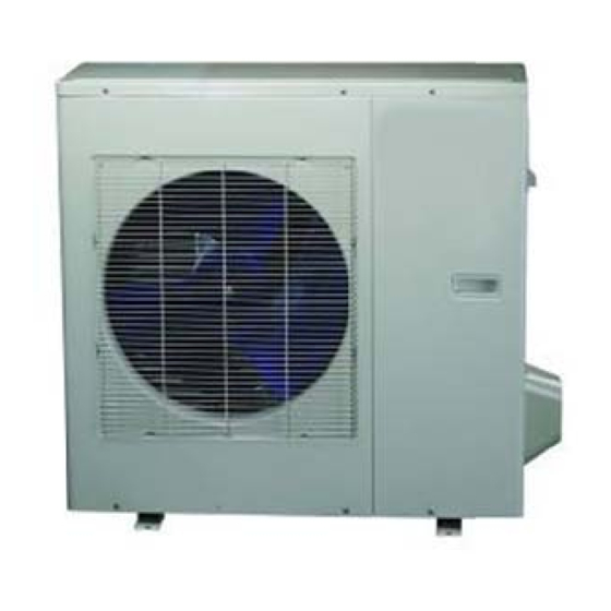
Page 5: External Appearance
AC-UTSM-2 2012--05 07C MCCU T Technical Ma nual External a appearanc MCCU U-7C(H)N2 MCCU-1 0C(H)N2, M MCCU-14C(H H)N2 MCCU- -16C(H)N2 MCCU U-22CN2, M MCCU-28CN CCU-22HN2 2, MCCU-28 8HN2 MCCU-35C C(H)N2 MC CCU-45C(H) -
Page 6: Refrigerant Cycle Diagram
R407C MCCU Technical Manual MCAC-UTSM-2012-05 6. Refrigerant cycle diagram Cooling only: 4.1 MCCU-7CN2 Cooling Outdoor heat-exchanger HP Switch Sight glass Filter drier Compressor LP Switch Solenoid valve Connection accessories Indoor unit 4.2 MCCU-10CN2,MCCU-14CN2 Cooling Outdoor heat-exchanger HP Switch Sight glass Discharge temp. - Page 7 MCAC-UTSM-2012--05 R407C MCCU Technical Manual 4.3 MCCU-16CN2 Cooling Outdoor heat-exchanger HP Switch Sight glass Discharge temp. sensor Filter drier Compressor LP Switch Liquid-gas seperator Solenoid valve Connection accessories Indoor unit 4.4 MCCU-22CN2, MCCU-28CN2, MCCU-35CN2 Cooling Outdoor heat-exchanger HP Switch Sight glass Discharge temp.
- Page 8 R407C MCCU Technical Manual MCAC-UTSM-2012-05 4.5 MCCU-45CN2 Cooling Heating Outdoor heat-exchanger HP Switch 4-way valve Sight glass Discharge temp. sensor Check valve LP Switch Compressor Liquid-gas seperator Filter drier Check valve Solenoid valve Connection accessories Indoor unit Cooling and heating: 4.6 MCCU-7HN2 Cooling Heating...
- Page 9 MCAC-UTSM-2012--05 R407C MCCU Technical Manual 4.7 MCCU-10HN2, MCCU-14HN2 Cooling Heating Outdoor heat-exchanger 4-way valve Sight glass Check valve HP Switch Filter drier Discharge temp. sensor Compressor Check valve LP Switch Solenoid valve Connection accessories Indoor unit 6.8 MCCU-16HN2 Cooling Heating Outdoor heat-exchanger HP Switch 4-way valve...
- Page 10 R407C MCCU Technical Manual MCAC-UTSM-2012-05 6.9 MCCU-22HN2, MCCU-28HN2 Cooling Heating Outdoor heat-exchanger HP Switch 4-way valve Muffler Sight glass Discharge temp. sensor Compressor Check valve LP Switch Liquid-gas seperator Filter drier Check valve Solenoid valve Connection accessories Indoor unit 6.10 MCCU-35HN2 Cooling Heating Outdoor heat-exchanger...
- Page 11 MCAC-UTSM-2012--05 R407C MCCU Technical Manual 6.11 MCCU-45HN2 Cooling Heating Outdoor heat-exchanger HP Switch 4-way valve Sight glass Discharge temp. sensor Check valve LP Switch Compressor Liquid-gas seperator Filter drier Check valve Solenoid valve Connection accessories Indoor unit...
-
Page 12: Connection Accessory List
Note: Midea CCU can be free connected with other indoor units, such as DX AHU, through a set of connection accessories which are listed above. Please install these accessories according to the piping diagram and the installation manual of each accessory. -
Page 13: Specifications
MCAC-UTSM-2012--05 R407C MCCU Technical Manual 8. Specifications – Cooling only Model MCCU-7CN2 MCCU-10CN2 MCCU-14CN2 MCCU-16CN2 Power supply 220-240V/1N/50Hz 380V/3N/50Hz 380V/3N/50Hz 380V/3N/50Hz Ambient temp. range ℃ 18~45 18~45 18~45 18~45 Capacity 7000 10000 14000 16000 Rated input 3133 4333 5500 6033 Max. - Page 14 R407C MCCU Technical Manual MCAC-UTSM-2012-05 (Continued) Model MCCU-22CN2 MCCU-28CN2 MCCU-35CN2 MCCU-45CN2 Power supply 380V/3N/50Hz 380V/3N/50Hz 380V/3N/50Hz 380V/3N/50Hz Ambient temp. range 18~45 18~45 18~45 18~45 ℃ Capacity 22000 28000 34000 45000 Rated input 8250 10000 13100 16000 Max. input 11500 14500 18000 24000 Cooling...
- Page 15 MCAC-UTSM-2012--05 R407C MCCU Technical Manual Specifications – Cooling and heating Model MCCU-7HN2 MCCU-10HN2 MCCU-14HN2 MCCU-16HN2 Power supply 220-240V/1N/50Hz 380V/3N/50Hz 380V/3N/50Hz 380V/3N/50Hz Ambient temp. range ℃ -10~45 -10~45 -10~45 -10~45 Capacity 7000 10000 14000 16000 Rated input 3133 4333 4956 6033 Max.
- Page 16 R407C MCCU Technical Manual MCAC-UTSM-2012-05 (Continued) Model MCCU-22HN2 MCCU-28HN2 MCCU-35HN2 MCCU-45HN2 Power supply 380V/3N/50Hz 380V/3N/50Hz 380V/3N/50Hz 380V/3N/50Hz Ambient temp. range -10~45 -10~45 -10~45 -10~45 ℃ Capacity 22000 28000 34000 45000 Rated input 10000 10800 13300 16000 Max. input 13500 14800 18500 24000 Cooling...
-
Page 17: Dimensions
MCAC-UTSM-2012--05 R407C MCCU Technical Manual 9. Dimensions 9.1 Dimensions of side discharge units Fig. 1-1 Fig. 1-2 Fig. 1-3 Table 1 (mm) Model Remark 7 kW 10 kW Fig 1-1 14 kW 16 kW 1167 Fig 1-2... - Page 18 7C MCCU T Technical Man nual MCAC C-UTSM-201 12-05 Dimensions s of vertical d discharge un nits—22kW, 28kW cooli ing only unit Fig. 1 Dimensions s of vertical d discharge un nits—22kW, 28kW cooli ing and hea ting units 1615 Fig.
- Page 19 AC-UTSM-2 2012--05 07C MCCU T Technical Manual Dimensions s of vertical d discharge un nits—35kW Fig. 1 Dimensions s of vertical d discharge un nits—45kW 1380 1630 Fig. 1...
-
Page 20: Wiring Diagram- Cooling Only
R407C MCCU Technical Manual MCAC-UTSM-2012-05 10. Wiring diagram- cooling only 10.1 MCCU-7CN2... - Page 21 MCAC-UTSM-2012--05 R407C MCCU Technical Manual 10.2 MCCU-10CN2...
- Page 22 R407C MCCU Technical Manual MCAC-UTSM-2012-05 10.3 MCCU-14CN2...
- Page 23 MCAC-UTSM-2012--05 R407C MCCU Technical Manual 10.4 MCCU-16CN2...
- Page 24 R407C MCCU Technical Manual MCAC-UTSM-2012-05 10.5 MCCU-22CN2...
- Page 25 MCAC-UTSM-2012--05 R407C MCCU Technical Manual 10.6 MCCU-28CN2...
- Page 26 R407C MCCU Technical Manual MCAC-UTSM-2012-05 10.7 MCCU-35CN2 WIRING DIAGRAM BLUE (OUTDOOR UNIT) R E D FUNCTI ON OF SWITC H W H I T E WHITE BLUE B L U E B L A C K FAN1 Y E L L O W N E T O F F N E T O N B L A C K...
- Page 27 MCAC-UTSM-2012--05 R407C MCCU Technical Manual 10.8 MCCU-45CN2...
- Page 28 R407C MCCU Technical Manual MCAC-UTSM-2012-05 Cooling and heating 10.9 MCCU-7HN2...
- Page 29 MCAC-UTSM-2012--05 R407C MCCU Technical Manual 10.10 MCCU-10HN2...
- Page 30 R407C MCCU Technical Manual MCAC-UTSM-2012-05 10.11 MCCU-14HN2...
- Page 31 MCAC-UTSM-2012--05 R407C MCCU Technical Manual 10.12 MCCU-16HN2...
- Page 32 R407C MCCU Technical Manual MCAC-UTSM-2012-05 10.13 MCCU-22HN2...
- Page 33 MCAC-UTSM-2012--05 R407C MCCU Technical Manual 10.14 MCCU-28HN2...
- Page 34 R407C MCCU Technical Manual MCAC-UTSM-2012-05 10.15 MCCU-35HN2 WIRING DIAGRAM BLUE (OUTDOOR UNIT) 黑 B L U E Y E L L O W WHITE F UNC TION OF SW ITC H BLUE R E D N E T O F F B L A C K FAN1 N E T O N...
- Page 35 MCAC-UTSM-2012--05 R407C MCCU Technical Manual 10.16 MCCU-45HN2...
- Page 36 7C CCU Tech hnical Manua MCAC C-UTSM-201 12-05 Exploded view- coo oling only 11.1 MCCU-7C Part Name BOM Co rt Name BOM Code Motor 202400400 0724 14.2 E-part box 20124820000 Motor b bracket 201245320 0906 14.3 Motor capa acitor 20240110035 Rear ne 201148200 0003...
- Page 37 MCAC-UTSM-2012--05 R407C MCCU Technical Manual 11.2 MCCU-10CN2 Part Name BOM Code Part Name BOM Code Motor 202400440401 11.4 Wire joint, 5p 202301450039 Motor bracket assy’ 201275590020 11.5 AC contactor 202300850046 Rear net 201148700000 11.6 Main control board assy’ 201347890001 Condenser assy’...
- Page 38 R407C CCU Technical Manual MCAC-UTSM-2012-05 11.3 MCCU-14CN2 Part Name BOM Code Part Name BOM Code 202400440401 11.5 202300850046 Motor AC contactor 201275590020 11.6 201347890001 Motor bracket assy’ Main control board assy’ 201148700000 11.7 202301450003 Rear net Wire joint,4p 201575690018 11.8 202300900551 Condenser assy’...
- Page 39 MCAC-UTSM-2012--05 R407C MCCU Technical Manual 11.4 MCCU-16CN2 Part Name BOM Code Part Name BOM Code 201575890056 201675890381 Condenser assy’ High pressure valve assy’ 201275600085 19.1 201600720098 Motor bracket assy’ Low pressure valve 202400400185 201675890383 Motor Discharge pipe assy’ 202400400186 20.1 201601200001 Motor Pipe joint...
- Page 40 7C CCU Tech hnical Manua MCAC C -UTSM-201 1 2-05 11.5 5 MCCU-22C...
- Page 41 MCAC-UTSM-2012--05 R407C MCCU Technical Manual Part Name BOM Code Part Name BOM Code Three-phase power top cover welding part 201275990072 12.12 202301600518 protection devices low pressure valve assy’ 201675990295 front-right support pillar 201275990070 Pipe joint 201601200004 asynchronism fan motor 202400400563 Valve body 201601600314 condenser assy’...
- Page 42 7C CCU Tech hnical Manua MCAC C -UTSM-201 1 2-05 11.6 6 MCCU-28C...
- Page 43 MCAC-UTSM-2012--05 R407C MCCU Technical Manual Part Name BOM Code Part Name BOM Code Welding together pieces 201275990102 Front right column 201275990109 of roof Low-pressure valve 201675990276 Induction motor 202400400456 assembly Pipe joint 201601200004 Condenser components 201575990014 Cube Valve 201601601291 15.1 Condenser 201575990015 Electronic...
- Page 44 7C CCU Tech hnical Manua MCAC C -UTSM-201 1 2-05 11.7 7 MCCU-35C...
- Page 45 MCAC-UTSM-2012--05 R407C MCCU Technical Manual Part Name Part Name Vertical plate Inlet pipe ass’y of condenser Air outlet grille Cover to E‐box Discharge pipe ass’y Fixing plate of E‐box Cover ass’y E‐box ass’y Axial fan 22.1 E‐box Middle rear vertical plate 22.2 Transformer Rear vertical plate 22.3 PCB ass’y Liquid‐gas seperator 22.4 Three‐phase protector Front panel 22.5 Compressor capacitor Left front vertical plate 22.6 Fixing board of wiring terminal Fixing plate of E‐box 22.7 Wiring terminal Right front vertical plate 22.8 Wiring terminal Three‐phase asynchronous motor ...
- Page 46 7C CCU Tech hnical Manua MCAC C -UTSM-201 1 2-05 11.8 8 MCCU-45C...
- Page 47 MCAC-UTSM-2012--05 R407C MCCU Technical Manual Part Name BOM Code Part Name BOM Code Front-right supporting Rear net 201295100172 201295100163 board Top cover 201195100000 Separator 201601100036 Axial flow fan 201100300205 201295100157 Cover board 201295100149 Motor bracket assy’ 201295100171 Middle supporting assy’ 201295100167 Baffle assy’...
- Page 48 7C CCU Tech hnical Manua MCAC C-UTSM-201 12-05 oling and heating 11.9 9 MCCU-7HN art Name BOM Cod Part Name BOM Cod Motor 2024004007 E-part box a assy’ 20337539001 Motor bra acket 2012453209 13.1 AC contacto 20230085004 Rear net 2011482000 13.2 Wire joint, 5 20230145003...
- Page 49 MCAC-UTSM-2012--05 R407C MCCU Technical Manual 11.10 MCCU-10HN2 Part Name BOM Code Part Name BOM Code Motor 202400440401 13.3 Wire joint 202301450117 Motor bracket assy’ 201275590020 13.4 Wire joint, 5p 202301450039 Rear net 201148700000 13.5 AC contactor 202300850046 Condenser assy’ 201575600020 13.6 Main control board assy’...
- Page 50 R407C CCU Technical Manual MCAC-UTSM-2012-05 11.11 MCCU-14HN2 Part Name BOM Code Part Name BOM Code Motor 202400440401 13.4 Wire joint, 5p 202301450039 Motor bracket assy’ 201275590020 13.5 AC contactor 202300850046 Rear net 201148700000 13.6 Main controller assy’ 201347890001 Condenser assy’ 201575790015 13.7 Wire joint,4p...
- Page 51 MCAC-UTSM-2012--05 R407C MCCU Technical Manual 11.12 MCCU-16HN2 Part Name BOM Code Part Name BOM Code Condenser assy’ 201575890058 19.1 Low pressure valve 201600720098 Motor bracket assy’ 201275600085 Discharge pipe assy’ 201675890379 Motor 202400400185 20.1 Branch pipe 201600500210 Motor 202400400186 20.2 Pressure controller 202301820025 Front panel...
- Page 52 7C CCU Tech hnical Manua MCAC C -UTSM-201 1 2-05 11.1 MCCU U-22HN2, MC CCU-28HN2 2...
- Page 53 MCAC-UTSM-2012--05 R407C MCCU Technical Manual Rear left vertical supporter 201295590027 High pressure valve 202301820005 Front right vertical supporter 201295590030 High temp. switch 202301820008 Rear right vertical supporter 201295590028 Low pressure valve assy’ 201657600010 Side cover panel 201295590012 20.1 Low pressure valve 201600710100 Top cover 201195590002...
- Page 54 7C CCU Tech hnical Manua MCAC C -UTSM-201 1 2-05 11.1 MCCU U-35HN2...
- Page 55 MCAC-UTSM-2012--05 R407C MCCU Technical Manual Part Name Part Name Vertical plate Fixing plate of E‐box Air outlet grille E‐box ass’y Discharge pipe ass’y 22.1 E‐box Check valve 22.2 Transformer Cover ass’y 22.3 PCB ass’y Axial fan 22.4 Three‐phase protector Middle rear vertical plate 22.5 Compressor capacitor Rear vertical plate 22.6 Fixing board of wiring terminal Liquid‐gas seperator 22.7 Wiring terminal Front panel 22.8 Wiring terminal Left front vertical plate 22.9 Relay Fixing plate of E‐box 22.10 Contactor...
- Page 56 7C CCU Tech hnical Manua MCAC C -UTSM-201 1 2-05 11.1 MCCU U-45HN2...
- Page 57 MCAC-UTSM-2012--05 R407C MCCU Technical Manual Front-right supporting Rear net 201295100172 201295100163 board Top cover 201195100000 Separator 201601100036 Axial flow fan 201100300205 201295100157 Cover board 201295100149 Motor bracket assy’ 201295100171 Middle supporting assy’ 201295100167 Baffle assy’ 201295030810 Wind baffle assy’ 201295030814 Below condenser assy’...
-
Page 58: Part 2 Installation
R407C CCU Technical Manual MCAC-UTSM-2012-05 Part 2 Installation 1. Note Install the unit where enough space of installation and maintenance is available. Install the unit where the ceiling is horizontal and enough for bearing the weight of the indoor unit. ... -
Page 59: Installation Steps
MCAC-UTSM-2012--05 R407C MCCU Technical Manual 2. Installation steps 2.1 Installation Check the model and name to avoid mistaken installation. 2.2 Refrigerant pipe The refrigerant pipes must have the specified diameter. Nitrogen of a certain pressure must be filled into the refrigerant pipe before welding. ... -
Page 60: Unit Location
R407C CCU Technical Manual MCAC-UTSM-2012-05 3. Unit location 3.1 When installing the unit, leave a space for maintenance shown in the following figure. Install the power supply at the side of the outdoor unit. 3.2 Ensure enough space for installation and maintenance. Side discharge units (Fig 2-1 and Fig 2-2): Fix with bolt Fig 2-1... - Page 61 MCAC-UTSM-2012--05 R407C MCCU Technical Manual Vertical discharge units (Fig 2-3 and Fig 2-4): Air outlet Air inlet Air inlet Fig 2-3 ≥1000 mm ≥1000 mm ≥500 mm ≥1000 mm ≥1000 mm Fig 2-4 Note: 1. In case any obstacles exist above the outdoor unit, such obstacles must be 2000mm above the outdoor unit. 2.
- Page 62 R407C CCU Technical Manual MCAC-UTSM-2012-05 3.4 Unit transportation Use 4 steel ropes of a Ф6mm or bigger size to hoist the unit and convey it into the room. In order to prevent scratch and deformity the unit, apply a guard board to the surface of contact between the steel ropes and the air conditioner.
- Page 63 AC-UTSM-2 2012--05 07C MCCU T Technical Ma nual Installatio on of refrig gerant pip 4.1 T The refriger rant pipe ada apter is loca ted inside th he outdoor u unit. When th he pipe is co onnected fro om the front side, pipe can be let out throu...
- Page 64 R407C CCU Technical Manual MCAC-UTSM-2012-05 4.6 Size of refrigerant pipes Model Gas side Liquid side MCCU-7CN2 Φ15.9 Φ9.52 Φ19 Φ12.7 MCCU-10CN2 MCCU-14CN2 Φ19 Φ9.52 MCCU-16CN2 Φ19 Φ9.52 Φ22 (Φ25, pipe length≥ MCCU-22CN2 Φ12.7 Cooling only 30m) Φ25 (Φ28, pipe length≥...
- Page 65 (Fig 2-11) Outdoor unit Max. pipe length L Indoor unit Fig 2-11 Table 1 (Unit: m) Model Max. pipe length L Max. high drop H MCCU-7CN2 MCCU-10CN2 MCCU-14CN2 MCCU-16CN2 Cooling only MCCU-22CN2 MCCU-28CN2 MCCU-35CN2 MCCU-45CN2 MCCU-7HN2...
-
Page 66: Piping Between Outdoor Unit And Indoor Unit
R407C CCU Technical Manual MCAC-UTSM-2012-05 5. Piping between outdoor unit and indoor unit 5.1 Preparation before Installation Check the height difference between the indoor unit and the outdoor unit, and check the length and number of bends of the refrigerant pipeline, which must meet the following requirements: ... - Page 67 MCAC-UTSM-2012--05 R407C MCCU Technical Manual 5.2.6. Put on an heat resistance envelope at connective pipe adapter of the indoor unit, and wrap it tight with the wrapping tape lest condensate and leakage. 5.3 Expelling Air 5.3.1 Select a method to expel air from the following table: Length of connective pipe Procedure of expelling air (single pass)
- Page 68 7C CCU Tech hnical Manua MCAC C-UTSM-201 12-05 Manifold va alve Multimete manomet -76cmHg -han ndle -handle Filler hose ler hose Lo p pressure va alve Fig 2-13 L Loosen and remove the maintenanc ce orifice nu t of valve A, , and connec ct the filler h hose of the m...
- Page 69 MCAC-UTSM-2012--05 R407C MCCU Technical Manual 5.5 Heat Insulation Use heat insulation materials to wrap the part protruding outside the flared pipe joint and the refrigerant pipe of the liquid pipe and the gas pipe, and ensure that no gap exists between them. ...
-
Page 70: Field Wiring
R407C CCU Technical Manual MCAC-UTSM-2012-05 6. Field wiring CAUTION: Use special power supply for the air conditioner. Design power supplies specific to the indoor unit and outdoor unit. The supply voltage must comply with the nominal voltage. The external supply circuit of the air conditioner must have a ground wire, and the power supply ground wire of the indoor unit must be connected with the external ground wire firmly. -
Page 71: Part 3 Trouble Shooting
MCAC-UTSM-2012--05 R407C MCCU Technical Manual Part 3 Trouble shooting 1. Malfunctions If any of the following malfunctions occur, stop operation of the air conditioner immediately. Turn off the power switch, and contact the local after sales service center of manufacturer: The fuse blows out frequently, or the circuit breaker protection occurs frequently. -
Page 72: Trouble Shooting
R407C CCU Technical Manual MCAC-UTSM-2012-05 2. Trouble shooting About the Fault of temperature sensor, high pressure protection, low pressure protection. Please refer to the following: Fault of temp. sensor Judge 1: Whether the sensor is break Connects it well. off. ... - Page 73 MCAC-UTSM-2012--05 R407C MCCU Technical Manual High pressure protection Judge 1: Whether the wiring between the high pressure switch Connect it well and main control board is connected well or correctly Judge 2: Whether the high pressure switch is broken Validate: Short connect the high pressure switch Replace high pressure switch socket, check whether the system can run normally Check whether the refrigerant system is ok...
- Page 74 R407C CCU Technical Manual MCAC-UTSM-2012-05 Low pressure protection Judge 1: The wiring between the low pressure switch and main control board is connected well or correctly Connect it well Judge 2: Whether the low pressure switch is broken Validate: Short connect the low pressure switch socket, check whether the system can run normally Replace low pressure switch Check whether the refrigerant system is ok...
Need help?
Do you have a question about the MCCU-7CN2 and is the answer not in the manual?
Questions and answers