Table of Contents
Advertisement
Advertisement
Table of Contents

Related Manuals for Ivy Biomedical Systems 3000 Series


Summary of Contents for Ivy Biomedical Systems 3000 Series
- Page 3 IVY Biomedical Systems, Inc. recommends that a telephone call or written request for service advice be made to IVY Biomedical Systems, Inc. Service Department. This product or any of its parts should not be repaired other than in accordance with instructions provided by IVY Biomedical Systems, Inc. trained personnel.
- Page 4 This page is intentionally left blank.
- Page 6 This page is intentionally left blank.
-
Page 7: Table Of Contents
Fuse Ratings ............................17 TESTING AND TROUBLESHOOTING......................18 MAINTENANCE AND CLEANING .......................23 Monitor................................23 Patient Cables ..............................23 Preventive Maintenance.............................23 ACCESSORIES..............................24 ECG ..................................24 Disposal................................24 SPECIFICATIONS ............................25 BOARD LAYOUTS AND SCHEMATICS .......................A ASSEMBLIES DRAWINGS AND SPARE PART LISTS ................B Model 3000 Series Service Addendum... - Page 8 Table of Contents This page is intentionally left blank. Model 3000 Series Service Addendum...
-
Page 9: Warranty
WARRANTY WARRANTY All products manufactured by Ivy Biomedical Systems, Inc. under normal use, are warranted to be free from defects in material and workmanship and to operate within published specifications, for a period of one year from date of original shipment. - Page 10 WARRANTY This page is intentionally left blank. Model 3000 Series Service Addendum...
-
Page 11: Introduction
INTRODUCTION INTRODUCTION This manual is to provide information on the correct use of the Model 3000 Series ECG and Heart Rate synchronizer/patient monitor. It is up to the user to ensure that any applicable regulations regarding the installation and operation of the monitor are observed. -
Page 12: Safety
300 µA. Explosion DANGER: Explosion hazard! Do not use this equipment in the presence of flammable anesthetics or other flammable substance in combination with air, oxygen-enriched environment or nitrous oxide. Model 3000 Series Service Addendum... -
Page 13: Patient Connections
If an alarm condition occurs while the alarms are set to off, neither visual or audio alarms will be present. The model 3000 Series should not be used within the magnetic field during Magnetic Resonance Imaging. Pacemakers Rate meters might continue to count the pacemaker rate during occurrences of cardiac arrest or some arrhythmias. - Page 14 WARNING: The use of the Model 3000 below the following amplitude values may cause inaccurate results: Minimum amplitude of patient physiological signal depending upon the type of patient cable. Patient cable part number Minimum amplitude 590161 1.5 mV 590317 0.5 mV 590323 0.5 mV Model 3000 Series Service Addendum...
- Page 15 Harmonic emissions Class A directly connected to the public low-voltage power IEC 61000-3-2 supply network that supplies buildings used for domestic purposes. Voltage fluctuations/ Complies flicker emissions IEC 61000-3-3 Model 3000 Series Service Addendum...
- Page 16 <5 % U (>95 % dip in U (>95 % dip in U for 5 sec cycle for 5 sec cycle Power frequency 3 A/m Not applicable Not applicable (50/60 Hz) magnetic field IEC 61000-4-8 Model 3000 Series Service Addendum...
- Page 17 Model 3000 should be observed to verify normal operation. If abnormal performance is observed, additional measures may be necessary, such as re-orienting or relocating the Model 3000. Over the frequency range 150 KHz to 80 MHz, field strengths should be less than 3 V/m. Model 3000 Series Service Addendum...
-
Page 18: Description Of Warning Labels
⏐⎯ Type CF applied part, Defibrillator proof. Equipotential ground connector adjacent to this symbol. Fuse type/rating. Output signal. _______ Input signal. ∼ Stand By (STBY) Alternate Current (AC) Input/Output signal Protective earth (ground) WEEE Compliance Model 3000 Series Service Addendum... -
Page 19: Monitor Description
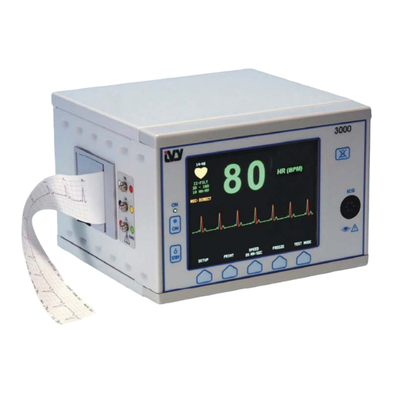
MONITOR DESCRIPTION The Model 3000 Series series Cardiac Trigger Monitor is an easy to use color monitor that displays a patient’s ECG waveform and heart rate. The ECG lead displayed can be selected from Leads I, II or III. In addition high and low heart rate alarm limits can be adjusted to bracket the patient’s heart rate so that a violation of these limits produces... -
Page 20: Control And Indicators
Use as a backspace when entering the patient ID. ON switch (Basic Key) Keypad (Only available in Model s 3100 and 3150) Stand By switch (Basic Key) Recorder ECG Patient Cable Connector Alarm Pause Programmable Keys Model 3000 Series Service Addendum... -
Page 21: Programmable Keys
Displayed above each programmable key is either a menu item or a function. Pressing a programmable key will display other menu levels or activate an appropriate function. Menu functions are described in the Menu Structure section of this manual. MENU STRUCTURE (Model 3000 with Polarity Control and Simulator option) Model 3000 Series Service Addendum... - Page 22 MONITOR DESCRIPTION MENU STRUCTURE (Model 3000 without Polarity Control and Simulator option) Model 3000 Series Service Addendum...
- Page 23 MONITOR DESCRIPTION Menu Structure Ethernet Mode (Model 3150) Model 3000 Series Service Addendum...
- Page 24 MONITOR DESCRIPTION Menu Structure Disk Transfer Mode (Model 3150 and 3100) Model 3000 Series Service Addendum...
-
Page 25: Display
SETUP: Selections made in the menu setup modes (alarm limits, lead selection, and filter on/off) are displayed in small characters at the upper left corner. ECG: Trace is displayed across the screen moving from left to right. Floppy Disk Mode display Ethernet mode display Model 3000 Series Service Addendum... -
Page 26: Alarm Messages
AUXILIARY: A digital interface for device communication. This auxiliary output provides 5V and -8Vwith a maximum current of 20mA. ETHERNET: This output provides an Ethernet protocol (10Base-T, IEEE 802.3) to allow the model 3000 Series and the CT scanner console to share data and control options. -
Page 27: Fuse Ratings
Selector Fuse Ratings The fuses are located behind the cover of the power entry module. To replace the fuses, remove the cover and replace them only with same type and rating T.5A, 250V (Metric 5x20mm). Model 3000 Series Service Addendum... -
Page 28: Testing And Troubleshooting
>0.5 V, a inoperable condition is indicated by flashing LEAD OFF indicator on the display. ECG Simulator (Optional) The model 3000 series can have an optional integrated simulator that is used to verify the integrity of the patient cable, lead wires and electronic circuits involved in the processing of the ECG signal. - Page 29 (Only 3100, 3150, and 3200) X ray function is off. There is a 3.5” floppy disk inside the floppy drive. • “DISK WRITE FAILED” message The floppy drive is not full. appeared. (Only 3100 and 3150) Model 3000 Series Service Addendum...
- Page 30 SELECT REMOVE VERIFY Black (LA) + White (RA) - Red (LL) ECG trace is clamped to 0. L II Black (LA) com LEAD OFF alarm tag is displayed. Red (LL) L III White (RA) com Model 3000 Series Service Addendum...
- Page 31 Verify that the trace is displayed in RED beginning at the peak of the test signal and corresponds with the trigger output pulse. Press the TRIGGER key in the ECG menu to disable the Trigger Mark and the trigger pulse. Model 3000 Series Service Addendum...
- Page 32 If a simulator is installed, connect the lead wires to the side terminals and verify operation in all lead configurations. Connect the ECG simulator and check for the correct heart rate and ECG display. If a recorder is present, verify operation. Model 3000 Series Service Addendum...
-
Page 33: Maintenance And Cleaning
• The LEAD OFF message is displayed when the patient cable is connected, but the patient leads are not connected. Connecting the patient leads together should make the message disappear. • The BNC Interconnect cable is clean and intact. NOTE: There are no user serviceable items contained in the model 3000 Series. Model 3000 Series Service Addendum... -
Page 34: Accessories
Disposal of devices or consumables must be done in accordance with local, state, and federal laws and regulations. WEEE Directive 2002/96/EC.- Do not dispose of WEEE products in general waste. At the end of life of product contact IVY Biomedical Systems, Inc. customer service for return instructions. Model 3000 Series Service Addendum... -
Page 35: Specifications
300 µV peak Sensitivity: Heart Rate Averaging: Exponential averaging calculated once a second with a maximum response time of 8 seconds. Response Time: ≤ 8 seconds Rejects T waves ≤R wave Tall T Wave Rejection: Model 3000 Series Service Addendum... - Page 36 Data Rates: 300bps to 115.2Kbps Standard Temperature: 32 to 158°F (0 to 70°C) Size: 1.574 x 1.929 in (40mm x 49mm) Mechanical Size: Height: 6.70in. (17.2cm) Width: 9.25in. (33.5cm) Depth: 9.21in. (23.4cm) Weight: 6.5lbs (2.9kg) Model 3000 Series Service Addendum...
- Page 37 35 VA Regulatory Unit meets or exceeds the specifications for the AAMI Cardiac Monitor Standard EC-13, UL2601-1, CAN/CSA C22.2 No 601.1-M90, CDN MDR (CMDCAS), IEC 60601-2-25, IEC 60601-2-27, MDD.93/42/EEC, CE 0143, ISO 13485:1996, and FDA/CGMP. Model 3000 Series Service Addendum...
- Page 38 SPECIFICATIONS This page is intentionally left blank. Model 3000 Series Service Addendum...
-
Page 39: Board Layouts And Schematics
BOARD LAYOUTS AND SCHEMATICS BOARD LAYOUTS AND SCHEMATICS DIAGRAMS 1. Adult 3 lead and ECG peak detector board (Mother board) 5148-00-01 2. ECG Isolated input board 5150-00-01 3. Power Supply board 5151-00-01 4. ECG Simulator board 5160-00-01 Model 3000 Series Service Addendum... - Page 40 BOARD LAYOUTS AND SCHEMATICS This page is intentionally left blank Model 3000 Series Service Addendum...
- Page 47 SHIELD_DR...
- Page 52 BOARD LAYOUTS AND SCHEMATICS This page is intentionally left blank Model 3000 Series Service Addendum...
- Page 53 ASSEMBLIES DRAWINGS AND SPARE PARTS 1. ASSEMBLIES a. 2700-00-01 Main Assembly, 3000 series b. 2699-00-01 Front Assembly, 3000 series c. 2698-00-01 Bottom Cover Assembly, 3000 series d. 2697-00-01 Rear Panel Assembly, 3000 series e. 2701-00-01 Final Assembly, 3000 series 2. IDENTITY KITS a.
- Page 54 ASSEMBLIES DRAWINGS AND SPARE PARTS This page is intentionally left blank. Model 3000 Series Service Addendum...
- Page 55 ASSEMBLIES 2700-00-01 MAIN ASSEMBLY, 3000 SERIES SEQ# PART# DESCRIPTION 2697-00-01 REAR PANEL ASSEMBLY, 3000 SERIES 2699-00-01 FRONT ASSEMBLY, 3000 SERIES 5148-00-01 ADULT 3 LEAD ECG & PEAK DETECTOR BOARD ASSEMBLY 721006 SCREW, PAN HEAD, PHIL, STEEL, No.4-40 x 3/8" LONG 721007 SCREW, PAN HD, PHIL, STEEL, No.4-40 x 1/4 "...
- Page 64 TY-RAP, BLACK NYLON, 2.875" LG 721006 SCREW, PAN HD, PHIL, STEEL, No.4-40 x .375" LG 730000 NUT, HEX, STEEL, No.4-40 740002 FLATWASHER, STEEL, No.4 740003 LOCKWASHER, INT. To6TH, STEEL, No.4-40 2643-01-11 CHASSIS, PAINTED 2827-00-10 INSULATOR, DISPLAY Model 3000 Series Service Addendum...
- Page 67 ASSEMBLIES DRAWINGS AND SPARE PARTS 2698-00-01 BOTTOM COVER ASSEMBLY, 3000 SERIES SEQ# PART# DESCRIPTION 2649-00-11 COVER, BOTTOM, PAINTED 680035 RUBBER BUMPER FOOT, GRAY, W/ INSERT, 3/4" DIA x 3/8" TALL 740007 LOCKWASHER, INT. TOOTH, STEEL, No.6 Model 3000 Series Service Addendum...
- Page 70 ASSEMBLIES DRAWINGS AND SPARE PARTS 2697-00-01 Rear Panel Assembly, 3000 series SEQ# PART# DESCRIPTION 680041 KIT, LINE CORD RETAINING CLIP 2522-01-10 HARNESS, INTERFACE FROM POWER SUPPLY TO MAIN BOARD 2616-00-10 HARNESS, SPEAKER 2625-01-10 HARNESS, ECG / LEAD OFF OUTPUT 2644-00-10...
- Page 75 MAIN ASSEMBLY, 3000 SERIES 721007 SCREW, PAN HD, PHIL, STEEL. No. 4-40 x ¼” LONG, NICKEL PL. 740003 LOCKWASHER, INT. TOOTH, STEEL. No. 4 2759-00-10 CAUTION TAG, LINE VOLTAGE SELECTOR 2785-00-10 LABEL, SECURITY SEAL 2844-00-10 LABEL, OVERLAY, NON-DISPOSAL Model 3000 Series Service Addendum...
- Page 78 LOCKWASHER, INT. TOOTH, STEEL, No.4 740021 LOCKWASHER, SPLIT, STEEL, No.4 2783-00-10 FRONT PANEL, GRAPHICS, MODEL 3100 2662-00-10 PLATE, ROLL STAND MOUNTING, 3000 SERIES 722001 SCREW, PAN HD, PHIL, STEEL, No.6-32 x 5/16" LONG 722008 SCREW, PAN HD, PHIL, STEEL, No.6-32 x 3/8" LONG 2750-00-10...
- Page 79 LOCKWASHER, INT. TOOTH, STEEL, No.4 740021 LOCKWASHER, SPLIT, STEEL, No.4 2783-01-00 FRONT PANEL, GRAPHICS, MODEL 3150 2662-00-10 PLATE, ROLL STAND MOUNTING, 3000 SERIES 722001 SCREW, PAN HD, PHIL, STEEL, No.6-32 x 5/16" LONG 722008 SCREW, PAN HD, PHIL, STEEL, No.6-32 x 3/8" LONG 2750-01-00...
- Page 80 2593-00-10 GASKET, RECORDER, XE-50 2608-01-10 HARNESS, RECORDER INTERFACE 380004 RECORDER, XE-50, THERMAL, 50mm 730010 NUT, ACORN, STEEL, No.4-40 740002 FLATWASHER, STEEL, No.4 740003 LOCKWASHER, INTERNAL TOOTH, No.4 590035 RECORDER PAPER, 50mm x 80’, NO GRID Model 3000 Series Service Addendum...
- Page 81 ECG SIMULATOR BOARD ASSEMBLY 210068 BANANA PLUG WITH ECG SNAP STUD 750054 STANDOFF, FEMALE, ALUMINUM, NO 4-40, ¼” HEX, 1.187” LONG 2772-01-15 KIT, ECG SIMULATOR SEQ# PART # DESCRIPTION 680040 HOLE PLUG, 17/32” (.531) DIAMETER, WHITE Model 3000 Series Service Addendum...
Need help?
Do you have a question about the 3000 Series and is the answer not in the manual?
Questions and answers