
Related Manuals for Ivy Biomedical Systems 3000 Series


Summary of Contents for Ivy Biomedical Systems 3000 Series
- Page 1 Model 3000 Series OPERATION MANUAL Cardiac Trigger Monitor © 2010 IVY Biomedical Systems Inc. All Rights Reserved. Part No. 2718-55-16 Part No. 2718-04-16...
- Page 3 IVY Biomedical Systems, Inc. recommends that a telephone call or written request for service advice be made to IVY Biomedical Systems, Inc. Service Department. This product or any of its parts should not be repaired other than in accordance with instructions provided by IVY Biomedical Systems, Inc. trained personnel.
- Page 4 This page is intentionally left blank.
-
Page 5: Declaration Of Conformity
Physiological Monitors Models: 3000 (Series) We, Ivy Biomedical Systems, Inc., hereby declare that the devices mentioned above comply with the Swedish National Board of Health and Welfare Regulation and guidelines on medical devices LVFS 2003:11 (M) 28 October 1994 – transposing European Medical Devices Directive 93/42/EEC. - Page 6 This page is intentionally left blank.
-
Page 7: Table Of Contents
Table of Contents Table of Contents WARRANTY ..............................iii INTRODUCTION ..............................1 SAFETY ................................2 Electrical ................................2 Explosion ................................2 Patient Connections .............................. 3 MRI ..................................3 Pacemakers ................................3 Electrosurgery Protection ............................ 3 Defibrillation Protection ............................3 EMC ..................................3 Electromagnetic Compatibility IEC 60601-1-2:2001 ................ - Page 8 Table of Contents RECORDER OPERATION ..........................24 Changing Paper ..............................24 Recorder Modes ..............................25 Recorder Speed ..............................26 Example Printout ..............................26 SYNCHRONIZED OUTPUT (TRIGGER) ...................... 27 The Synch Pulse ..............................27 Trigger-Mark Display ............................27 Polarity Control Option ............................. 28 MONITOR TESTING ............................
-
Page 9: Warranty
WARRANTY WARRANTY All products manufactured by Ivy Biomedical Systems, Inc. under normal use, are warranted to be free from defects in material and workmanship and to operate within published specifications, for a period of one year from date of original shipment. - Page 10 WARRANTY This page is intentionally left blank. Model 3000 Operation Manual...
-
Page 11: Introduction
Incorrect operation or failure of the user to maintain the monitor in accordance with proper maintenance procedures relieves the manufacturer or his agent from all responsibility for consequent non-compliance, damage, or injury. Ivy Biomedical Systems, Inc. 11 Business Park Drive... -
Page 12: Safety
SAFETY SAFETY Electrical This product is intended to be operated from a mains power source of nominally 100 to 230V~, 47 to 63 Hz and Maximum AC Power consumption: 35VA. WARNING: Before this monitor is plugged into any power source verify visually that the line selector switch on the rear panel displays the appropriate voltage range for your location. -
Page 13: Patient Connections
SAFETY Patient Connections Patient connections are electrically isolated. For all connections use isolated probes. Don’t let patient connections contact other conductive parts, including ground. See instructions for patient connections in this manual. Carefully route patient cables to reduce the possibility of patient entanglement or strangulation. Leakage current is limited internally by this monitor to less than 10 μA. - Page 14 SAFETY CAUTION: Portable and mobile RF communications equipment can affect medical electrical equipment. WARNING: The model 3000 should not be used adjacent to or stacked with other equipment and that if adjacent or stacked use is necessary, the Model 3000 should be observed to verify normal operation in the configuration in which it will used.
- Page 15 SAFETY Guidance and manufacturer’s declaration – Electromagnetic emissions The Model 3000 is intended for use in the electromagnetic environment specified below. The customer or the user of the Model 3000 should assure that it is used in such an environment. Emissions test Compliance Electromagnetic environment - guidance...
- Page 16 SAFETY Guidance and manufacturer’s declaration – Electromagnetic immunity The Model 3000 is intended for use in the electromagnetic environment specified below. The customer or the user of the Model 3000 should assure that it is used in such an environment. Immunity test IEC 60601 test Compliance level...
- Page 17 SAFETY Guidance and manufacturer’s declaration – Electromagnetic immunity The Model 3000 is intended for use in the electromagnetic environment specified below. The customer or the user of the Model 3000 should assure that it is used in such an environment. Immunity test IEC 60601 test Complianc...
-
Page 18: Description Of Warning Labels
SAFETY Description of Warning Labels Attention, consult ACCOMPANYING DOCUMENTS before attempting to change power supply selection or carry out interconnections. Equipment connected should comply with IEC-60601-1 or IEC-950 with configuration to IEC-60601-1-1. ♥ Type CF applied part, Defibrillator proof. Equipotential ground connector adjacent to this symbol. -
Page 19: Monitor Description
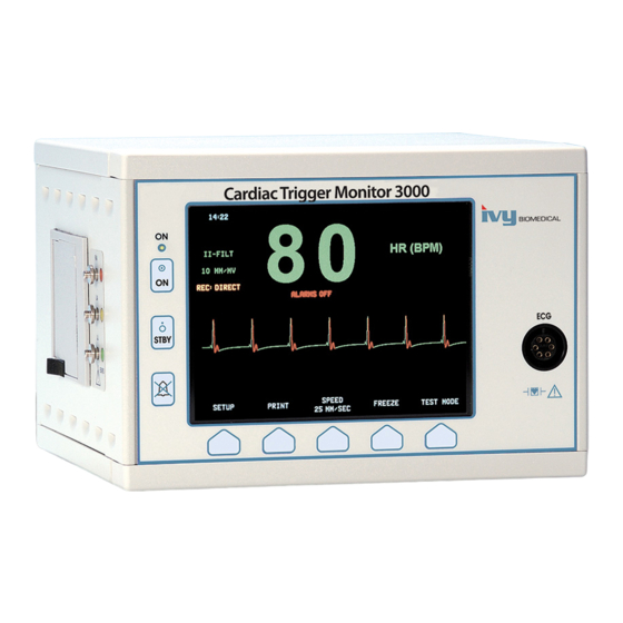
MONITOR DESCRIPTION The Model 3000 series Cardiac Trigger Monitor is an easy to use color monitor that displays a patient’s ECG waveform and heart rate. The ECG lead displayed can be selected from Leads I, II or III. In addition high and low heart rate alarm limits can be adjusted to bracket the patient’s heart rate so that a violation of these limits produces... -
Page 20: Control And Indicators
MONITOR DESCRIPTION Controls and Indicators Basic Keys When the monitor is plugged into an AC power source the ON switch, when pressed, provides power to the monitor’s electronic circuits. The STBY switch, when pressed, disconnects power from the monitor’s electronic circuits. NOTE: To disconnect the monitor from the main power unplug the AC power cord. -
Page 21: Menu Structure (With Polarity Control And Simulator Option)
MONITOR DESCRIPTION MENU STRUCTURE (with Trigger Polarity control) Model 3000 Operation Manual... -
Page 22: Menu Structure (Without Polarity Control And Simulator Option)
MONITOR DESCRIPTION MENU STRUCTURE (without Trigger Polarity Control) Model 3000 Operation Manual... -
Page 23: Display
MONITOR DESCRIPTION Display HEART RATE: Displayed in beats per minute (bpm) on the upper part of the screen. SETUP: Selections made in the menu setup modes (alarm limits, lead selection, and filter on/off) are displayed in small characters at the upper left corner. ECG: Trace is displayed across the screen moving from left to right. -
Page 24: Alarms
MONITOR DESCRIPTION ALARMS: The following alarm indications are displayed in reverse video. Alarm indications appear on the center of the screen and flash once per second . ALARMS PAUSE message (PAUSE) is also displayed on the center of the screen and is displayed in red text. ALARMS OFF: The audible and visual alarms have been turned off. -
Page 25: Fuse Ratings
MONITOR DESCRIPTION The use of ACCESSORY equipment not complying with the equivalent safety requirements of this equipment may lead to a reduce level of safety of the resulting system. Consideration relating to the choice shall include: • Use of the accessory in the PATIENT VICINITY •... -
Page 26: Monitor Setup
MONITOR SETUP MONITOR SETUP To Setup the Instrument for operation WARNING: Before this monitor is plugged into any power source verify visually that the line selector switch on the rear panel displays the appropriate voltage range for your location. For further instructions see “To change mains voltage” below. Plug the ac line cord into a power source providing the proper voltage. -
Page 27: Trace Speed
MONITOR SETUP To set the Trace Speed Use the following procedure to change the trace speed. Press the [SPEED] key in the main menu to select the trace speed. Selections are 25, and 50 mm/s. NOTE: The [SPEED] key also changes the speed of the recorder. Default Settings To reset the monitor to the default settings, turn monitor off by pressing the STBY key;... -
Page 28: Alarm Messages
ALARM MESSAGES ALARM MESSAGES The following alarm message is displayed in reverse video of white letters on a red back ground. ALARMS OFF :All audible and visual alarms have been turned off: To turn all audible and visual ALARMS ON press key once. -
Page 29: Ecg Monitoring
ECG MONITORING ECG MONITORING When ECG monitoring, the ECG waveform moves across the display. The heart rate, heart rate alarm limits, and lead selection are displayed in the upper left corner together with alarm messages. Also, a heart symbol flashes each time a heartbeat is detected. -
Page 30: Patient Connections
ECG MONITORING Patient Connections To ensure compliance with both safety and performance specifications, use the patient cables supplied by Ivy Biomedical Systems (see Accessories). Other cables might not produce reliable results. Use only high quality pre gel silver/silver-chloride electrodes or equivalent. Use the following procedure for ECG monitoring: Before applying the electrodes, use Nuprep gel or a gauze pad to gently clean the area where the electrodes will be applied. -
Page 31: Lead Selection
ECG MONITORING HR(BPM Use the third programmable key [SIZE] to adjust the ECG waveform amplitude. Press [EXIT] to return to the main menu. Low Signal Message If the amplitude of the ECG signal is between 300µV and 500µV (3-5mm of amplitude at size 10mm/mv) for a period of eight seconds a LOW SIGNAL message will be displayed in yellow below the ECG waveform. -
Page 32: Ac Power Filter
ECG MONITORING Select [LEAD] to change the lead selection. The current lead selection is shown above the alarm limits in the upper left portion of the display. Available lead selections are Lead I, Lead II, or Lead III. Press [EXIT] to return to the main menu. AC Power Filter Use the following procedure to activate the AC Power filter: Press the [SETUP] key from the main menu. -
Page 33: Alarm Limits
ECG MONITORING Alarm Limits Press the [SETUP] key from the main menu. The following menu appears. HR(BPM Press the programmable key [LIMITS] to enter the Alarm Limits menu. Use the programmable keys to set the high and low heart rate limits. ... -
Page 34: Recorder Operation
RECORDER OPERATION RECORDER OPERATION (Optional) Changing Paper Replace the roll of thermal paper as follows. (Recorder paper is Ivy P/N: 590035) Press the paper eject button to open the door at the front of the recorder. Press Here If the door does not open completely, pull it toward you until it is completely open. Reach in and remove the spent paper core by pulling it gently toward you. -
Page 35: Recorder Modes
RECORDER OPERATION Hold the paper against the pinch roller and close the door. Recorder Modes Use the following procedure to select the printing mode to be used. Selections are DIRECT, TIMED and DELAY. The print mode is indicated in the left center of the display. Press the [SETUP] key from the main menu. -
Page 36: Recorder Speed
RECORDER OPERATION Direct To print in direct, press the [PRINT] key. Press [PRINT] again to stop printing. The plot is preceded by a header which contains all parameter readings and the time/date. The speed of the plot and vertical resolution are the same as the display. The plot is labeled with the speed of the plot in mm/s, the recorder mode, and the parameters. -
Page 37: Synchronized Output (Trigger)
SYNCHRONIZED OUTPUT SYNCHRONIZED OUTPUT (Trigger) The Synch Pulse The ECG Synchronized Output produces a trigger pulse starting at the peak of each R-wave , which is available on the SYNCHRONIZED OUTPUT BNC connector and on the ECG X1000 (ECGX500 for GEMS Nuclear Medicine Applications) output connector, ring on the ¼”... -
Page 38: Polarity Control Option
SYNCHRONIZED OUTPUT Trigger Polarity Control (available for some OEM customers) The trigger polarity control allows the user to change the polarity of the trigger pulse to either positive edge (0V to 5V) or negative edge (5V to 0V). Use the following procedure to set the polarity of the trigger pulse: Press the [SETUP] key in the main menu. -
Page 39: Monitor Testing
MONITOR TESTING MONITOR TESTING Press the [TEST] key to test the internal functions of the monitor. You should do this each time you begin monitoring a patient. The [TEST] function generates a 1 mV pulse at 70 bpm, causing a waveform and a 70 bpm indication on the display and a signal at the rear panel connector. -
Page 40: Maintenance And Cleaning
MAINTENANCE AND CLEANING MAINTENANCE AND CLEANING The Monitor When necessary, clean the exterior surfaces of the monitor with a cloth or swab dampened with a warm water and mild detergent solution. Do not allow liquids to enter the interior of the instrument. CAUTION: •... -
Page 41: Accessories
Disposal of devices or consumables must be done in accordance with local, state, and federal laws and regulations. WEEE Directive 2002/96/EC.- Do not dispose of WEEE products in general waste. At the end of life of product contact IVY Biomedical Systems, Inc. customer service for return instructions. Model 3000 Operation Manual... -
Page 42: Specifications
SPECIFICATIONS Specifications Lead Selection: LI, LII, LIII menu selectable. Patient Cable: 6-Pin AAMI Standard connector Isolation: Isolated from ground related circuits by >4 kV rms, 5.5 kV peak ≥90 dB with patient cable and 51 kΩ/47 nF imbalance CMRR: ≥20 MΩ at 10 Hz with patient cable Input Impedance: Frequency Response LCD:... - Page 43 SPECIFICATIONS Pacer Pulse Rejection Width: 0.1 to 2 ms at ±2 to ±700 mV Overshoot: Between 4 to 100ms and not greater than 2mV. Fast ECG signals: 2mV/100µs. Detector disabling: None. NOTE: Pacemaker pulses are not present in any rear panel outputs. Alarms High Rate: 15 to 250 bpm in 5 bpm increments...
- Page 44 SPECIFICATIONS Synchronized Output (Trigger) Phase Delay from Electrode Leads to Trigger Output: < 3 ms ±50µs typical @ 1 mV input R to R Trigger Accuracy: Pulse width: 1 to 150ms (standard 150ms) Pulse amplitude: 0 to 5V, 5 to 0V, -11 to 11V <100 Ω...
Need help?
Do you have a question about the 3000 Series and is the answer not in the manual?
Questions and answers