Table of Contents
Advertisement
Quick Links
Advertisement
Table of Contents
Troubleshooting

Related Manuals for Ivy Biomedical Systems 101R

Summary of Contents for Ivy Biomedical Systems 101R
- Page 1 Model 101R/NR Patient Monitor R-wave Trigger Service Manual...
- Page 2 Copyright © 1999 by Ivy Biomedical Systems, Inc., Branford, Connecticut. All rights reserved. No part of this manual may be reproduced without the permission of Ivy Biomedical Systems, Inc. 101R/NR0999 2409-00-20 REV 00...
-
Page 3: Table Of Contents
The Trigger Pulse ...............................13 Trigger-Spot Display ............................13 ECG MONITORING............................14 Safety Considerations............................14 Patient Connections............................15 ECG Waveform Amplitude (Size)........................15 Lead Selection ..............................16 ECG Filter................................16 Alarm Limits...............................17 RECORDER OPERATION ..........................18 Changing Paper ..............................18 Recorder Menus..............................19 Recorder Modes..............................20 ALARM MESSAGES ............................22 Model 101R/NR Service Manual... - Page 4 ECF Filter...............................30 X1000 Output............................30 ECG Gain ...............................30 A/D Converter............................30 Cardiotach................................31 Peak Detector ............................31 Rate Computation...........................32 Alarm Generation...........................32 CRT Signals ................................32 Vertical Deflection ..........................32 Horizontal Deflection..........................32 Horizontal Correction..........................32 Unblanking.............................33 Audio Circuits..............................33 ECG Audio.............................33 Alert Audio.............................33 Digital Circuitry..............................34 Model 101R/NR Service Manual...
- Page 5 Removing the CRT .............................47 Replacing the Main Power LED........................47 Removing the Recorder Assembly ........................47 Removing the Mother Board ..........................48 Replacing the Touch Panel ..........................48 PURCHASING INFORMATION........................49 Part List................................49 Terms and Conditions............................49 BOARD LAYOUT DIAGRAMS ........................A SCHEMATICS DIAGRAMS ..........................B Model 101R/NR Service Manual...
-
Page 6: Warranty
(at our option). Fuses and batteries are not covered under this warranty. During the first year of service, there is no charge for parts or labor. In the second year of service, the customer is charged for labor only. Model 101R/NR Service Manual... -
Page 7: Introduction
INTRODUCTION INTRODUCTION This manual is to provide information on the correct use of the Model 101R/NR monitor. It is up to the user to ensure that any applicable regulations respecting the installation and operation of the monitor are observed. Manufacturer's Responsibility... -
Page 8: Safety
Pacemakers: Rate meters might continue to count the pacemaker rate during occurrences of cardiac arrest or some arrhythmias. Do not rely on rate meter alarms. Keep pacemaker patients under close surveillance. Model 101R/NR Service Manual... -
Page 9: Electrosurgery
Protective earth (ground) adjacent to this symbol. Internal connection on mains connector/filter. Equipotential earth connector adjacent to this symbol. ♥ ⎯⏐ ⏐⎯ Type CF equipment, Defibrillator proof. Fuse type/rating. _______ ⏐ = OFF, ⏐= ON. ∼ Alternate Current (AC) Output signal. DANGER HIGH VOLTAGE Model 101R/NR Service Manual... -
Page 10: Monitor Description
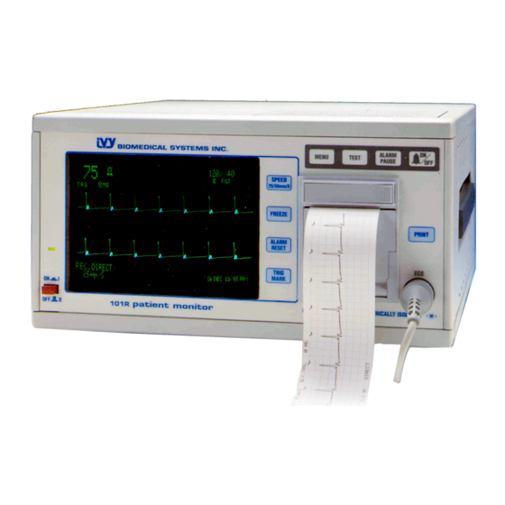
MONITOR DESCRIPTION MONITOR DESCRIPTION The Model 101R/NR Portable Patient Monitor is a dual trace monitor for ECG and heart rate, which produces an output pulse corresponding in time to the R-wave. The monitor is intended primarily for use in timed imaging studies, TMR/PMR and any application requiring precision R-wave synchronization. - Page 11 14.25 cm by 10.2 cm, 17.5 cm diagonal Sweep Speed: 25, 50 mm/s Mechanical Size: Height: 6.25 in. (16 cm) Width: 12.5 in. (31 cm) Depth: 16.0 in. (40 cm) Weight: < 20 lbs (9 kg) Model 101R/NR Service Manual...
- Page 12 (to change mains operating voltage see text on Monitor Setup). Maximum ac Power Consumption: 85 VA Safety Unit meets or exceeds the specifications for the AAMI Cardiac Monitor Standard. Units meet UL544, CSA, and CE-MDD 93/42/ECC requirements. ISO-9001 Approval # 98-1044. Model 101R/NR Service Manual...
-
Page 13: Control And Indicatiors
This is used to ensure that the monitor is functioning correctly. Turns the alarm audio on and off. When off, the ALARMS OFF message is displayed on the left side of the screen. Activates recorder. Push to start, push again to stop. (101R) Model 101R/NR Service Manual... -
Page 14: Programmable Keys
Press FREEZE again to resume movement. Resets the audible and visual indicators for an alarm that has been activated. Enables the Trigger-Spot feature, which highlights the point in the ECG waveform when the trigger output pulse occurs. Model 101R/NR Service Manual... -
Page 15: Menu Structure
MONITOR DESCRIPTION MENU STRUCTURE HIGH TRIG. DELAY (101R) Model 101R/NR Service Manual... -
Page 16: Display
PEQ GROUND: Potential Equalization - A ground connection that can be used to ensure that no potential differences can develop between this equipment and other electrical equipment. FUSE: Replace only with the same type and rating of fuse as indicated on the fuse rating label. Model 101R/NR Service Manual... - Page 17 100V ⏐ 120V 220V ⏐ 230V Trigger Polarity T 1.6 Amp T 1.0 Amp Voltage Selection 250V 250V 120 Vac wheel 5mm x 20mm 5 mm x 20 mm Fuse (Beneath Panel) Power Input 85VA 50/60Hz Model 101R/NR Service Manual...
-
Page 18: Monitor Setup
1. Locate power entry module in Rear Panel. 2. Remove line cord. 3. Pry down entry cover. 4. Locate and remove voltage wheel and set for appropriate voltage. 5. Replace fuse with proper size (see fuse rating). 6. Replace cover. Model 101R/NR Service Manual... -
Page 19: Trigger Output
Press TRIG MARK again to disable Trigger-Spot. Optional Trigger Delay Trigger delay is user adjustable by using the Trigger Delay menu. Range is from 0 to 700 ms in 5 ms increments. Intensity modulation highlights position of ECG where delay occurs. Model 101R/NR Service Manual... -
Page 20: Ecg Monitoring
Rate meters might continue to count the pacemaker rate during occurrences of cardiac arrest or some arrhythmias. Do not rely on rate meter alarms. Keep pacemaker patients under close surveillance. Model 101R/NR Service Manual... -
Page 21: Patient Connections
Use the following procedure to adjust the amplitude (size) of the displayed ECG waveform. 1. Press the MENU key once. The first menu appears. LIMITS TRIGGER DELAY RECORDER 2. Press the first programmable key (SPEED 25/50 mm/s) once to select ECG. Model 101R/NR Service Manual... -
Page 22: Lead Selection
Select [FILTER] to turn the filter on or off. The filter on/off indication is shown in the upper right portion of the display. The filter sets the frequency response of the displayed waveform as follows: Filtered: 0.5 to 25 Hz Unfiltered: 0.5 to 45 Hz Model 101R/NR Service Manual... -
Page 23: Alarm Limits
Decreases high HR limit Increases low HR limit Decreases low HR limit Each time you press a key, the corresponding limit changes by 5 bpm. The current limits are always shown in the upper left portion of the display. Model 101R/NR Service Manual... -
Page 24: Recorder Operation
Pull some paper from the roll. Make sure the sensitive (shiny) side of the paper faces the print head. The shiny side of the paper normally faces inside the roll. Align the paper with the pinch roller on the door. Print Head Pinch Roller Model 101R/NR Service Manual... -
Page 25: Recorder Menus
The paper should advance one inch. If the paper doesn’t move, open the door and repeat starting at step 5. Recorder Menus The recorder user interface is through the menu structure of the 101R/NR. 1. Press the MENU key to display the main menu.. -
Page 26: Recorder Modes
The plot is preceded by a header which contains all parameter readings and the time/date. The speed of the plot and vertical resolution are the same as the display. The plot is labeled with the speed of the plot in mm/s, the recorder mode, and the parameters. Model 101R/NR Service Manual... - Page 27 Press the programmable key (FREEZE) to increase what the cursor is under or press the programmable key (ALARM RESET) to lower what the cursor is under. After changing the settings press the programmable key (TRIG MARK) to ENTER the settings. Model 101R/NR Service Manual...
-
Page 28: Alarm Messages
HR HIGH The high heart rate alarm limit has been exceeded for four seconds. HR LOW The low heart rate alarm limit has been exceeded for four seconds. ASYSTOLE The interval between heartbeats has exceeded six seconds. Model 101R/NR Service Manual... -
Page 29: Monitor Testing
Safety checks should be performed at regular intervals or in accordance with local or governmental regulations. In the event that internal adjustment or recalibration is necessary, refer to the Service Manual for this equipment. Model 101R/NR Service Manual... -
Page 30: Cleaning
Do not allow liquids to enter the interior of the instrument. Patient Cables Do not autoclave the patient cables. Wipe the cables using soap and water or alcohol. Never submerge the cables in any liquid or allow liquids to enter the electrical connections. Model 101R/NR Service Manual... -
Page 31: Accessories
590170 Patient Leads 590162 BNC Interconnect Cable Assembly 1564-01-10 8 ft long Box of 10 rolls of recorder paper 590035 (101R) Disposal Disposal of devices or consumables must be done in accordance to natural environmental laws. Model 101R/NR Service Manual... -
Page 32: Theory Of Operation
It is on where a pixel is to be brightened and off where the pixel is darkened. When the crt beam reaches the bottom of one row of pixels (one raster) a retrace occurs, sending the beam to the top of the next raster to be drawn. Model 101R/NR Service Manual... -
Page 33: Timer Circuit
(the HV potentiometer), and sends it back to the High Voltage Module. It is used to keep the 6500 volt output of the High Voltage Module within tolerances. When the 6500 volt output is within tolerance, the -100 and +275 volt outputs should also be within tolerance. Model 101R/NR Service Manual... -
Page 34: Adjustment Circuit
TREND INT signal is allowed to enter the CATHODE signal. Finally, the diode prohibits current from flowing the wrong way through the circuit. As a whole, the trend intensity buffer sinks current from the CATHODE signal for the desired effects. Model 101R/NR Service Manual... -
Page 35: Low Voltage Power Supplies
Lead Selection Lead select switch U45 selects proper signals according to the levels of the L0 and L1 signals from the digital circuitry. These signals are set according to the lead selection made by the user. Model 101R/NR Service Manual... -
Page 36: Test Signal Generation
The A/D converter is U21 along with amplifier U22A. The converter samples the analog ECG signal and generates a series of 1,024 eight-bit numbers which can be stored in memory and then sent through the D/A converter for ECG waveform display. Model 101R/NR Service Manual... -
Page 37: Cardiotach
The Trigger Output at the rear panel connector is derived from the EVENT signal. This output is one 1 ms pulse for each QRS complex, with the leading edge corresponding to the peak of the R wave. The signal level is -12 V to Model 101R/NR Service Manual... -
Page 38: Rate Computation
The second signal is an S-shaped waveform generated by U17A, which integrates the parabolic signal from U17B. This S-shaped signal, when added to the horizontal ramp has the effect of slowing the beam near the edges of the Model 101R/NR Service Manual... -
Page 39: Unblanking
U13 and transistors Q19 and Q20, which drive the speaker. Alert Audio The ALRT AUDIO is enabled by the output from U36 Pin 18 in the digital circuit The ALERT AUD signal passes through volume adjust potentiometer RV11 to the audio amplifier U13. Model 101R/NR Service Manual... -
Page 40: Digital Circuitry
U29 to generate the D/A signal that gets switched into the vertical deflection signal during ECG waveform display. For raster display, the microprocessor sends the data through U36 and U15 to generate the Z signal. This signal brightens the crt at the proper times to generate the characters. Model 101R/NR Service Manual... -
Page 41: Testing And Troubleshooting
Verify that ECG Leads I, II, and III display properly. Change the heart rate on the simulator to 40 bpm. Notice the following: • The HR LOW message appears over the ECG trace. • Heart rate value of 40 ±1 bpm is displayed. Model 101R/NR Service Manual... - Page 42 Press ON/OFF. The ALARMS OFF message goes off. Adjust the high heart rate limit to 100 bpm. Set the simulator heart rate to 120 bpm. The HR HIGH message is displayed, and an audible alarm sounds. Model 101R/NR Service Manual...
-
Page 43: Troubleshooting
The Mother Board has all circuitry for processing the ECG, computing heart rate, and generating the alarms and the audio. Therefore, any problems with these functions are caused by problems on the Mother board. Once you have determined the major component causing the problem, refer to the Disassembly section for instructions on replacement. Model 101R/NR Service Manual... -
Page 44: Troubleshooting Table
1. Mother Board No Audio At All 1. Mother Board Audio 2. Connection to Speaker 3. Speaker No Alarm Audio 1. Alarm On/Off Setting 2. Mother Board No ECG Audio 1. Rear Panel switch setting 2. Mother Board Model 101R/NR Service Manual... -
Page 45: Block Diagram
CONVERTOR MULTIPLEXER VERTICAL Q15, Q16 DEFLECTION RASTER GENERATOR CONVERTOR TRIGGER PEAK CIRCUITRY TRIGGER DETECTOR U18A, U12 OUTPUT U23B ISOLATED TEST CIRCUIT PROTECTION LEAD NOTCH CIRCUITS SELECT FILTER U26C INPUT SHIELD DRIVE ECG X1000 BUFFER MOTHER BOARD Model 101R/NR Service Manual... -
Page 46: Voltage Measurements
Smaller of above must be 6.5 V; neither more than 7.0 V. Normal: 5.0 V ±200 mV +5 V Measure at +5 TP Normal: +5 reading ±100 mV Measure at -5 TP Both 5 V must be within 100 mV of each other. Model 101R/NR Service Manual... -
Page 47: Key Signals
Mother Board. See Mother Board layout for test point locations. For each of the following the signals, trigger the oscilloscope (negative) on Raster Enable (RE test point). Raster Enable RE Test Point Vertical Deflection Signal Vi Test Point Model 101R/NR Service Manual... - Page 48 To verify operation of the High Voltage Power Supply board, check the dc voltages as indicated in the Voltage Measurements section (High Voltage Power Supply). Also check the following dc filament voltages at the crt socket harness. brown Normal: 4.9 to 5.1 V -7 V black Normal: -6.8 to -7.1 V Model 101R/NR Service Manual...
-
Page 49: Adjustment Procedure
To test the auto notch function, plug unit into a variable freq. power generator and slowly change the line freq. from 50 to 60 Hz. Peak Detector With the oscilloscope, look at the signal at U23 Pin 7. Model 101R/NR Service Manual... -
Page 50: Crt Display
Press FREEZE and release TEST so that there are no pulses. Press the MENU button. Adjust RV9 (RSTP) so that the right end of the trend line just touches the left of side the menu box. Repeat the above steps as necessary. • Vertical Adjustments Model 101R/NR Service Manual... - Page 51 20 µA. With the line cord grounded, measure between shorted patient leads and the hot side of the ac line. The reading should be less than 10 µA. Model 101R/NR Service Manual...
-
Page 52: Assembly And Disassembly
Remove the connector from the back of the crt. Remove the crt anode cap from the front of the crt by pulling up on the rubber from the edges. Pull the High Voltage Power Supply board up and out of the card guides. Model 101R/NR Service Manual... -
Page 53: Removing The Yoke
Push in a new LED and replace the retainer. Removing the Recorder Assembly Open the recorder door and remove the paper from the recorder. Loosen the two captive Philips-head screws inside the recorder housing. Pull the Recorder Assembly straight out from the monitor. Model 101R/NR Service Manual... -
Page 54: Removing The Mother Board
Make sure the clear plexiglas window is in place in the bezel. Then feed the ribbon cable on the new Touch Panel through the slot in the bezel. Peel the protective backing from the Touch Panel and carefully press the panel onto the front bezel. Connect J203 (ribbon cable) to the Mother Board. Model 101R/NR Service Manual... -
Page 55: Purchasing Information
• A 15% restocking charge will be made on an instrument returned for credit or exchange, unless a waiver is issued, in writing, by an employee of Ivy Biomedical Systems, Inc. • One instruction manual and service instructions are supplied with each instrument. Additional copies may be ordered at $25 each. -
Page 56: Board Layout Diagrams
BOARD LAYOUT DIAGRAMS This page is intentionally left blank Model 101R/NR Service Manual... - Page 57 BOARD LAYOUT DIAGRAMS BOARD LAYOUT DIAGRAMS Model 101R/NR Service Manual...
- Page 61 SCHEMATICS SCHEMATICS Model 101R/NR Service Manual...
- Page 62 SCHEMATICS This page is intentionally left blank Model 101R/NR Service Manual...
- Page 65 J201-27 |C:\ORCAD\SHEET\SH5119\5119-003.SCH -12V .1UF 49.9K 1N4148 1.47M |C:\ORCAD\SHEET\SH5119\5119-004.SCH -12V 10000PF |C:\ORCAD\SHEET\SH5119\5119-005.SCH AUDIO_LO AUDIO_OFF J201-15 IVY BIOMEDICAL SYSTEMS INC. J201-10 11 BUSINESS PARK DRIVE .1UF MP 3.01K 301K AUDIO_SHIELD BRANFORD, CT. 06405 SPEAKER_GND J201-23 (203) 481-4183 .022UF MP J201-18 .0047UF MP 30.1K...
- Page 66 MC34002P 2. LAST USED: C144,D73,F4,FB4,J207,JP5, L1,LD3,Q48,R274,RN2,RV19, T1,TP43,U54,Y1. .01UF MP .1UF H.CTR. 3. NOT USED: JP2,JP3,U19,U37,U50. -12V 20K TOP IVY BIOMEDICAL SYSTEMS INC. 1N4148 11 BUSINESS PARK DRIVE BRANFORD, CT. 06405 9.09K (203) 481-4183 RASTER Title MC34002P 5K TOP MOTHER BOARD 1 ASSY, WITH RECORDER OPTION...
- Page 67 U30A 3. NOT USED: JP2,JP3,U19,U37,U50. R194 C120 U39C 470UF 2N3903 TO SHT. 4 CD4538B 100UF R196 2N3903 R211 16uSEC_SYNC IVY BIOMEDICAL SYSTEMS INC. MC34004P 3.32K IRF522 R210 C102 C103 11 BUSINESS PARK DRIVE R199 R195 R193 R212 R188 .001UF 22UF 2N3903 BRANFORD, CT.
- Page 68 2. LAST USED: C144,D73,F4,FB4,J207,JP5, L1,LD3,Q48,R274,RN2,RV19, R115 CLK1 2N3903 T1,TP43,U54,Y1. TO SHT. 3 OUT1 +12V 3. NOT USED: JP2,JP3,U19,U37,U50. CLK2 IVY BIOMEDICAL SYSTEMS INC. R152 OUT2 9.09K CS54 11 BUSINESS PARK DRIVE BRANFORD, CT. 06405 U22A (203) 481-4183 SOCKET 28 PIN...
Need help?
Do you have a question about the 101R and is the answer not in the manual?
Questions and answers