Table of Contents
Advertisement
Quick Links
Advertisement
Table of Contents

Subscribe to Our Youtube Channel
Related Manuals for Cynosure Potenza P1-08


Summary of Contents for Cynosure Potenza P1-08
- Page 1 OPERATOR MANUAL JMUM_PTZ_03, Rev. 1, 10/2020...
-
Page 3: Table Of Contents
TABLE OF CONTENTS CHAPTER 1 – INTRODUCTION Purpose and Scope Potenza Overview Intended Use of the Potenza Component List CHAPTER 2 – SAFETY General Safety Medical Safety Contraindications Warnings Caution Precautions Potential Side Effects Electrical Safety Cautions for Installation and Transportation 2.10 Preventive Check or Maintenance Repair Parts CHAPTER 3 –... - Page 4 AC Handpiece Tip (Applied Part) Neutral Electrode (Return Pad) (Applied Part) Footswitch Other Accessories CHAPTER 4 – INSTALLATION Operating environment Unpacking Conditions for Device Installation Installation of Main Body Installation of Tips 4.5.1 Installation of Motorised Needle Tip 4.5.2 How to disassemble the motorised tip (reverse order of installation) 4.5.3 Installation of One-Needle Tip 4.5.4...
- Page 5 CHAPTER 8 – PACKAGING Main Body and Handpieces Disposable Products Labels 8.3.1 Main Body 8.3.2 Accessories 8.3.3 Symbols CHAPTER 9 – SYSTEM Kinds of Pop-Up Messages Kinds of Guide Messages CHAPTER 10 – TECHNICAL SPECIFICATION 10.1 RF Type 10.2 Power 10.3 Frequency 10.4...
-
Page 6: Chapter 1 - Introduction
CHAPTER 1 INTRODUCTION 1.1 Purpose and Scope This Operator Manual provides information on configuration, components, intended use, features, caution and instructions about how to operate the Potenza. CAUTION All Personnel involved with the operation or maintenance of Potenza must be thoroughly trained and ✗... - Page 7 TABLE 1: DEVICE LIST Name Quantity Remarks Main Body 1 unit Motor handpiece 1 ea. Handpiece AC Handpiece 1 ea. I-49 5 ea. S-49 10 ea. I-25 10 ea. Starter kit S-25 20 ea. CP-21 10 ea. One needle: A1-15 5 ea.
-
Page 8: Chapter 2 Safety
• The Potenza device should only be used by physicians and staff who have been appropriately trained. • If a problem occurs when using the Potenza, please contact the Cynosure Customer Service. • Do not attempt to repair and modify the Potenza. - Page 9 • The entire area of the neutral electrode pad should be securely attached to the client’s body as close to the treatment site as possible. • The client must not come into contact with metal parts which are earthed or which have an appreciable capacitance to earth (i.e., operating table supports, etc.).
-
Page 10: Caution
Regularly check that the neutral electrode pad cable connections are intact. Poor neutral electrode pad contact may lead to low RF delivery and/or a system error condition. • When setting HF output, the maximum output voltage should not exceed the rated accessory voltage. •... -
Page 11: Precautions
• The container, which is attached to the handpiece stand, can accommodate up to 3 kg. • The lithium battery should be replaced by Cynosure service personnel only. • Non-continuous mode: Activation time: Max 30min / Deactivation time: Min 10min 2.6 Precautions... -
Page 12: Electrical Safety
2.8 Electrical Safety POWER SAFETY Check whether power cord is securely plugged into the outlet. Connect to a power dl source that meets device and electrical specifications. Otherwise, the equipment may malfunction. Do not use if the electric wire is damaged in any way. It may result in a fire due to electric leakage. - Page 13 • Use only Cynosure-supplied components and accessories. • Since it may cause electric shock, be careful not to allow ingress of any liquid to this product •...
-
Page 14: Cautions For Installation And Transportation
• To avoid the risk of electric shock, the Potenza must only be connected to a supply main with protective earth. • If disassembled or external cover opened by persons other than authorised service personnel, it may result in exposure to high voltage or high current. Never remove the cover of the handpiece or the main body. •... -
Page 15: Chapter 3 Description
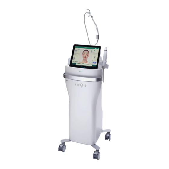
CHAPTER 3 DESCRIPTION 3.1 Overview The Potenza is a microneedling device which generates RF frequency of 1 or 2MHz that cause soft tissue coagulation through tissue heating. A total of 13 microneedle tips that attach to one of two of handpieces are available for treatments and should be used in accordance with the clinical reference guide (CRG). -
Page 16: Main Body
3.2 Main Body 3.2.1 Front and Rear FRONT REAR FRONT Name Function Motor Handpiece Holster Receptacle that securely holds the motor handpiece Delivery method for the electrosurgical device, which includes mounted Motor Handpiece electrodes that coagulate the tissue using high-frequency current Touchscreen user interface and display where adjustments to Operation Panel (LCD) treatment settings can be made... - Page 17 REAR Name Function Handpiece Holster Receptacle that securely holds the handpiece Port connecting the main body of the device to the handpiece via a Motor Handpiece Port cable (motor handpiece position compatible) Mains Power Switch Mains power on and off switch for the device Power Cable Socket Socket for connecting the power cable AC Handpiece Port...
-
Page 18: Side
3.2.2 Side SIDE NAME FUNCTION Handpiece Holsters Receptacles that securely hold the handpieces Delivery method for the electrosurgical device, which includes mounted Handpiece electrodes that coagulate the tissue using high-frequency current Operation Panel (LCD) Touchscreen user interface and display where Operation Panel (LCD) adjustments to treatment settings can be made Cable Stand... -
Page 19: Handpiece (Applied Part)
3.3 Handpiece (Applied Part) There are two types of handpieces available for use with the Potenza: the motor handpiece and the AC handpiece. One or the other will be used depending on the treatment type. 3.3.1 Motor Handpiece The motor handpiece automatically inserts the needles into the skin using a stepping motor. Because the needles are quickly inserted into and retracted out of the skin, it reduces the pain of the treatment. -
Page 20: Ac Handpiece
3.3.2 AC Handpiece The AC handpiece is used with a disposable one-needle tip while in monopolar mode. Type of disposable tips: 0.8mm, 1.2mm and 1.5mm tip; depth is adjustable by installing a new tip. P1-08 (0.8mm) A1-12 (1.2mm) A1-15 (1.5mm) 1. -
Page 21: Motor Handpiece Tip (Applied Part)
3.5 Motor handpiece Tip (Applied Part) 1. Relevant tip: Appearance PART DESCRIPTION Needle Case Protects the needles from damage Inserted into skin or tissue of client, delivering high-frequency energy. Insertion depth is Needle adjustable depending upon the treatment parameters set via the touchscreen 2. -
Page 22: Ac Handpiece Tip (Applied Part)
3.6 AC Handpiece Tip (Applied Part) • The tip that connects to the AC Handpiece that has only one needle. PART DESCRIPTION Tip Protection Cap Protects needle during storage One-Needle Tip Inserted into skin or tissue of client, delivering high-frequency energy Tip Connection Port Where the disposable needle tips are connected The following table shows the tips available for use with the AC Handpiece. -
Page 23: Neutral Electrode (Return Pad) (Applied Part)
3.7 Neutral Electrode (Return Pad) (Applied Part) The neutral electrode (return pad) is an accessory that must be attached to the client’s body during treatment while in monopolar mode. High-frequency current introduced to the body through the needle tip is returned via the return pad. -
Page 24: Footswitch
3.8 Footswitch The footswitch activates RF energy in the treatment tips. PART DESCRIPTION Plug Part which connects to the main body Safety Cover Safety cover to protect the switch and to prevent unintended output Switch Pressed with the foot to control the device’s energy output 3.9 Other Accessories 3.9.1 POWER CORD 3.9.2 HANDPIECE STAND... -
Page 25: Chapter 4 Installation
CHAPTER 4 INSTALLATION 4.1 Operating environment • Operating temperature: +100C to +350C • Humidity: 0% to 75% • Atmospheric Pressure: 700hPa~1060hPa (use at altitudes < 3000m) 4.2 Unpacking Unpack the product and remove the transparent film attached to the LCD touchscreen. CAUTION If the transparent film is not removed, the touch function of the LCD monitor may not work properly. -
Page 26: Installation Of Main Body
4.4 Installation of Main Body Handpiece cannot be repaired directly by the user; it can only be repaired by Cynosure service NOTE technicians. (See contact information on page 2.) Connect the Power Cord, Footswitch and Return Pad, Locate the ports for the power cord, footswitch and return pad on the rear part of the device and connect the proper cables to them. - Page 27 2. How to Connect the Neutral Electrode (Return Pad) Cable Peel off coating Insert the tab on Press the Check the LCD screen on pad. the return pad into connector lever for the Connection the connector. all the way down. Complete status 3.
-
Page 28: Installation Of Tips
4.5 Installation of Tips 4.5.1 Installation of Motorised Needle Tip CAUTION Since the tips are sterilised products, wearing medical-grade gloves during installation is recommended. ✗ 1. Insert the tip into handpiece 20 degrees counterclockwise from the center. 2. Turn the tip clockwise until it clicks to fasten. 4.5.2 How to disassemble the motorised tip (reverse order of installation) 1. -
Page 29: How To Disassemble The One-Needle Tip (Reverse Order Of Installation)
4.5.4 How to Disassemble the One-Needle Tip (reverse order of installation) 1. Turn the tip to the left with protection cap when removing the tip. 2. Remove it from handpiece. Chapter 4 Installation... -
Page 30: Chapter 5 Operating Instruction
CHAPTER 5 OPERATING INSTRUCTION 5.1 Preparation for Use 1. Turn on the main power switch on the rear part of the device. 2. Press the Power switch on the rear of monitor on the upper part of the device. 3. When a password window appears on the screen, enter the password. When the Potenza voice and logo come together, touch anywhere to operate the device. - Page 31 4. 1. Press the lesion you want to go to the Standard mode procedure screen. 2. Press the System Preferences icon to go to service screen. 3. Press the Manual icon to go to manual mode procedure screen. 4. Press ‘>’ icon to move to the 2nd page of the screen. Press ‘<’...
- Page 32 Operation Pick up the desired handpiece and connect the desired tip. The tip will automatically be displayed on the screen. BACK Previous screen navigator Lesion Name The lesion selected identifier on the Standard mode screen 1Mhz/2Mhz Frequency selection BI/MONO Bipolar or monopolar selection Pulse count display (current pulses/remaining pulses): resets the current Pulses pulse count to 0 when the reset button is pressed;...
- Page 33 6. Manual Mode Screen Operation Pick up the desired handpiece and connect the desired tip. The tip will automatically be displayed on the screen. BACK Previous screen navigator 1Mhz/2Mhz Frequency selection BI/MONO Bipolar or monopolar selection Pulse count display (current pulses/remaining pulses): resets the current pulse Pulses count to 0 when the reset button is pressed;...
- Page 34 Tip selection: displays the tip of the currently connected handpiece; pressing Tip Display Window the button allows the user to view other tips available for the device Treatment power level selection; can adjust from 0-50W by pressing the up or POWER(W) down arrow mJ/Pulse...
-
Page 35: Turning Off Device
5.2 Turning Off Device 1. Press the POWER switch. 2. After the LCD touchscreen has powered off, turn off the main switch on the rear of the device. 5.3 Disposal Used Tips cannot be reused, reprocessed or re-sterilised. Therefore, they must be processed according to the sharps protocol of the medical facility to prevent possible cross-contamination or infection. -
Page 36: Chapter 6 Storage & Transportation
3. Hold the handle of device and transport it to a place that complies with 4.3 Conditions for Device Installation and then install again according to 4.4 Installation. 4. To transport further than within your local office, contact Cynosure Customer Service (page 2) for assistance. CAUTION Do not hold the LCD monitor during transportation;... -
Page 37: Chapter 7 Cleaning & Maintenance
• Every part must be repaired and maintained exclusively by Cynosure Service technicians. • After cleaning the device, move to a secure and clean location. • To purchase additional accessories and parts (such as disposable tips), please contact your local Cynosure representative or contact Customer Service (see page 2). -
Page 38: Chapter 8 Packaging
CHAPTER 8 PACKAGING 8.1 Main Body and Handpieces → 8.2 Disposable Products FRACTIONAL MICRONEEDLE TIP ONE-NEEDLE TIP Chapter 8 Packaging... -
Page 39: Labels
8.3 Labels 8.3.1 Main Body Device Label Chapter 8 Packaging... -
Page 40: Accessories
8.3.2 Accessories HANDPIECE FOOT SWITCH Motor handpiece AC handpiece Neutral Electrode Pad Neutral Electrode Pad Cable Hand-piece Stand TIP (STARTER KIT INCLUDED) Fractional Microneedle Tip ( S-25, I-25, S-16, I-16) Fractional Microneedle Tip (CP-21) One Microneedle Tip (A1-15) Chapter 8 Packaging... -
Page 41: Symbols
8.3.3 Symbols SYMBOL DESCRIPTION SYMBOL DESCRIPTION Keep electrical waste separate from Type BF Applied Part municipal waste Equipotentiality Refer to instruction manual Earth-referenced patient circuit Dangerous voltage ON (power) No pushing OFF (power) No sitting Part number No stepping on surface Date of Manufacture Caution Manufacturer... -
Page 42: Chapter 9 - System
Connect a handpiece. handpieces entering treatment screen Faulty mainboard communication port or faulty UI board Communication port is Contact Cynosure Customer Service to communication port or faulty not responding check the device setting. mainboard to UI board cable connection AC Power Hz differs from setting... - Page 43 Check the return pad connection and if it than 750 in monopolar mode during is perfectly attached to patient. If problem procedure is not solved, contact Cynosure Customer Service to check the device setting High energy may cause Pressing ready button when the set Check the energy setting and decrease the side effect.
-
Page 44: Kinds Of Guide Messages
9.2 Kinds of Guide Messages MESSAGE POSSIBLE CAUSES RECOMMENDED ACTIONS SELECT HANDPIECE More than two HPs are connected and HP Select a handpiece. is not selected (recommended HP blinks) MONO DEDICATED TIP Connecting the monopolar-exclusive tip To use bipolar mode, insert the in bipolar mode or pressing bipolar mode bipolar-available tip. - Page 45 1MHZ SELECTED / Selecting 1Mhz / 2Mhz 2MHZ SELECTED BIPOLAR SELECTED Selecting Bipolar / Monopolar / MONOPOLAR SELECTED AUTO ON/ AUTO OFF Selecting Auto On / Auto Off PORT’1/2/3’ ‘MOTOR/ Selecting handpiece, display port ACN’ HP SELECTED STAND BY SELECTED / Selecting STAND BY / TREAT TREAT SELECTED STANDBY...
-
Page 46: Chapter 10 Technical Specification
CHAPTER 10 TECHNICAL SPECIFICATION 10.1 RF Type Bipolar, Monopolar 10.2 Power Max 50 watts 10.3 Frequency 1Mhz, 2Mhz 10.4 Repetition Rate 0.5-3.0 sec (0.1 sec step) 10.5 Handpieces 100-7043-001: Motorised Handpiece 100-7043-002: AC Handpiece 10.6 Tips MOTORISED HANDPIECE AC HANDPIECE 100-7043-051: S-16 100-7043-060: P1-08 100-7043-052: S-25... -
Page 47: Dimensions
10.10 Dimensions 503.2mm (W) x 365.6mm (L) x 316mm (H) (Incl. cable stand: 550.16mm (W) x 701mm (L) x 366mm (H)) 10.11 Weight 12.5kg 10.12 Cart 478mm (W) x 482.1mm (L) x 967.2mm (H), 32.26kg 10.13 Footswitch Specification Footswitch button: IPX8 10.14 Sterilisation Motor Handpiece tip and AC Handpiece tip were sterilised by ethylene oxide. - Page 48 GUIDANCE AND MANUFACTURER’S DECLARATION - ELECTROMAGNETIC IMMUNITY The Potenza is intended for use in the electromagnetic environment specified below. The customer or the user of the Potenza should assure that it is used in such an environment. Immunity IEC 60601 Compliance Electromagnetic Environment Test...
- Page 49 GUIDANCE AND MANUFACTURER’S DECLARATION - ELECTROMAGNETIC IMMUNITY The Potenza is intended for use in the electromagnetic environment specified below. The customer or the user of the Potenza should assure that it is used in such an environment. Test Level IEC Compliance Immunity Test Electromagnetic Environment - Guidance...
-
Page 50: Lifetime
Recommended separation distances BETWEEN PORTABLE AND MOBILE RF COMMUNICATIONS EQUIPMENT AND THE POTENZA The POTENZA is intended for use in an electromagnetic environment in which radiated RF disturbances are controlled. The customer of the user of the POTENZA can help prevent electromagnetic interference by maintaining a minimum distance between portable and mobile RF communications equipment (transmitters) and the POTENZA as recommended below, according to the maximum output power of the communications equipment. - Page 52 Cynosure Australia Cynosure (Australia) Pty Ltd 14-16 Suakin St, Pymble NSW 2073 +61 2 9484 4546 | infoaustralia@cynosure.com cynosureaustralia.com © 2020 Cynosure, Inc. ALL RIGHTS RESERVED. Cynosure is a registered trademark of Cynosure, Inc. Potenza is a trademark of Cynosure, Inc.
Need help?
Do you have a question about the Potenza P1-08 and is the answer not in the manual?
Questions and answers