
Subscribe to Our Youtube Channel
Related Manuals for Cynosure Cynergy


Summary of Contents for Cynosure Cynergy
- Page 1 Cynergy ™ TECHNICAL GUIDE 850-1265-000, Rev. 4 CYNOSURE ® Where art and science meet.
- Page 2 This manual is intended for both U.S. and International distribution. ™ Cynergy is a trademark of Cynosure, Inc. ® Cynosure is a registered trademark of Cynosure, Inc. © 2005 Cynosure, Inc. All rights reserved. Document #850-1265-000, Rev. 4, 7/06...
-
Page 3: Table Of Contents
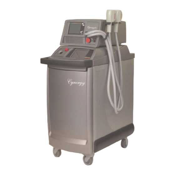
Glossary of Symbols and Abbreviations .................7 Section 1 Introduction.......................9 Disclaimer ........................9 Contacting Customer Service ..................9 About the Laser......................10 Figure 1–Cynergy, Cynergy PL and Cynergy III ..........10 About the Technical Guide ...................11 Section 2 Equipment Safety....................13 Introduction........................13 Potential Hazards ......................13 Optical Hazard ....................13 Electrical Hazard....................14... - Page 4 Figure 4–Cynergy System Block Diagram ............25 High Voltage Power Supply Module................26 Capacitor Bank Module ....................26 Figure 5–Capacitor Bank Module..............27 IGBT/Simmer Module ....................28 Figure 6–IGBT/Simmer Module...............28 Figure 7–Snubber Circuit..................29 Front Control Panel Module ..................30 Figure 8–Front Panel Display/Control Module ..........30 Cal Port Assembly ....................30 Laser Control Board......................31...
- Page 5 Figure 23A–‘Primary Diagnostic Routine’ Flowchart ........58 PFN Diagnostic Routine ...................59 Laser Head Diagnostic Routine ................60 Figure 23B–‘Laser Head Diagnostic Routine’ Flowchart ........60 Beam Train Diagnostic Routine................61 Figure 23C–‘Beam Train Diagnostic Routine’ Flowchart........61 Cynergy Technical Guide 850-1265-000, Rev. 4 3 of 112...
- Page 6 Servicing–HVPS Module................83 Replacing the High Voltage Power Supply Module.............83 Calibrating the HVPS ....................83 Section 12 Servicing–IGBT/Simmer Module..............85 Replacing IGBT/Simmer Module Shelf ...............85 Replacing Low Voltage Power Supply.................85 Replacing IGBT Triple Driver PCB, PDL..............86 4 of 112 850-1265-000, Rev. 4 Cynosure, Inc.
- Page 7 Calibrating the Resonator Port, YAG ................99 Calibrating the Resonator Port, PDL ................100 Calibrating the Cal Port, YAG..................101 Calibrating the Cal Port, PDL..................102 Section 19 Servicing–Final Check..................103 Final Check Procedure....................103 Section 20 Troubleshooting ....................105 Troubleshooting ......................105 Cynergy Technical Guide 850-1265-000, Rev. 4 5 of 112...
- Page 8 Fault Code Table.....................105 Self Test ......................107 Troubleshooting Chart ..................108 Transferring Diagnostic Data................109 Figure 26A–USB Access Panel Location ............109 Figure 26B–USB Slot Location..............110 Appendix A Laptop Computer..................111 Attaching a Laptop Computer..................111 HyperTerminal Setup....................111 6 of 112 850-1265-000, Rev. 4 Cynosure, Inc.
-
Page 9: Glossary Of Symbols And Abbreviations
Glossary of Symbols and Abbreviations The following international symbols and abbreviations may be used on the Cynergy lasers and/or in this manual. Symbols Declaration of Conformity to Optical Fiber Applicator Medical Device Directive 93/42/EEC per EN60601-2-22: 1996 CE Mark to Directive 93/465/EEC... - Page 10 This page has been intentionally left blank. 8 of 112 850-1265-000, Rev. 4 Cynosure, Inc.
-
Page 11: Introduction
Cynosure does not accept responsibility for personal injury or property damage resulting from the servicing of Cynosure equipment by its customers or by third parties, except where such injury or damage is a direct result of Cynosure’s negligence. Customers, by accepting the service... -
Page 12: About The Laser
There are two upgrade paths that are planned for this product. One path involves taking a V-Star in this chassis and adding the YAG resonator and controls to become a Cynergy. The other takes a Cynergy and adds the MultiPlex option which allows the user to deliver both wavelengths in a single pulse. -
Page 13: About The Technical Guide
♦ Calibration Procedures The Cynergy Technical Guide applies to the Cynergy and the Cynergy MultiPlex systems. The Cynergy Service Manual, doc. 850-1270-100, includes this technical guide, the operator manual, and a comprehensive drawing set and procedures that will aid in the understanding of salient mechanical and electrical assemblies. - Page 14 This page has been intentionally left blank. 12 of 112 850-1265-000, Rev. 4 Cynosure, Inc.
-
Page 15: Equipment Safety
Potential Hazards Optical Hazard The PDL side of the Cynergy laser generates laser light at a wavelength of 585 nm ± 2% with a maximum energy of approximately 8 joules delivered from the handpiece. The YAG side generates laser light at a wavelength of 1064 nm with a maximum energy of approximately 63 joules delivered from the handpiece. -
Page 16: Electrical Hazard
45 seconds. Monitor the voltage on the capacitors with a DVM probe to ensure it is at a safe level. IMPORTANT: The Cynergy laser system, the capacitor bank does not dump when going between laser states (Ready to Standby) or between laser wavelengths. The only time it dumps is when the user selects Utility. -
Page 17: Fire Hazard
Never direct the laser beam onto any surface except a power meter or an appropriate beam dump. Chemical Hazard The Cynergy laser uses a dye medium. Handle the dye with care, both to protect against toxicity and against staining. Operators should follow these precautions: ♦... - Page 18 This page has been intentionally left blank. 16 of 112 850-1265-000, Rev. 4 Cynosure, Inc.
-
Page 19: Laser System Controls
30 minutes to resolve itself. After the dye concentration has reached an acceptable level, the system will not adjust the dye concentration unless the laser is restarted. Cynergy Technical Guide 850-1265-000, Rev. 4 17 of 112... -
Page 20: System Check
Cynergy MultiPlex The Cynergy MultiPlex mode consists first of a PDL pulse, set at any fluence for a 7- or 10-mm HP followed by a YAG laser pulse with similar adjustments. Pulse widths are controlled by 8 pulse groups that assign clinically relevant pulse width combinations to the two lasers. -
Page 21: Operating Modes, Service
Attach a laptop as detailed in “Appendix A” starting on page 111. Turn on the laser and press “q” and press enter to access the DOS prompt. Type “CV” and then enter to access CV Mode. Cynergy Technical Guide 850-1265-000, Rev. 4 19 of 112... - Page 22 Figure 2A–Performance Diagnostic Flow Diagram 20 of 112 850-1265-000, Rev. 4 Cynosure, Inc.
- Page 23 Figure 2B–Normal Operation Flow Diagram Cynergy Technical Guide 850-1265-000, Rev. 4 21 of 112...
- Page 24 Figure 2C–Cynergy MultiPlex Flow Diagram 22 of 112 850-1265-000, Rev. 4 Cynosure, Inc.
-
Page 25: Laser Description
Main Modules Refer to Figures 3A and 3B for the location of the main modules that comprise the laser system. Figure 3A–Main Modules, Front View Cynergy Technical Guide 850-1265-000, Rev. 4 23 of 112... - Page 26 Figure 3B–Main Modules, Rear View Figure 4 shows the relationships of the main components in the Cynergy laser. The diagram indicates AC is brought into the laser through the voltage select PCB, and then is directed to the HVPS directly and to the isolation transformer. At the AC distribution PCB, the AC is separated into circuits with their own solid-state relays and fusing.
- Page 27 Figure 4–Cynergy System Block Diagram NOTE: See schematic, 105-1865-000 for a detailed system-wiring diagram. Cynergy Technical Guide 850-1265-000, Rev. 4 25 of 112...
-
Page 28: High Voltage Power Supply Module
24,000µF in 1.3 seconds (750 to 1000VDC). To select the power supply charge rate, see section on setting the voltage” in the Cynergy Quick Install Guide. The power supply control voltage set’s the capacitor bank voltage and is a 0 to 8Vdc analog signal which corresponds to “150V... - Page 29 TX1 is also used for the fuse short signal. If TX1 turns on and the laser is not in the dump mode, a fuse short condition is recorded and displayed on the front panel. Cynergy Technical Guide 850-1265-000, Rev. 4...
-
Page 30: Igbt/Simmer Module
IGBT. Figure 6–IGBT/Simmer Module One of the unique features of the Cynergy laser is that both the YAG laser and the PDL use the energy stored in the capacitor bank PCB. Each driver board has its own isolated power supply, mounted to each PCB, ensuring that each IGBT is isolated from primary side AC power and power coming from the LVPS. - Page 31 An optical transmitter located on the simmer board will then turn on, sending an optical signal to the laser control board as an indication of simmer status. Cynergy Technical Guide 850-1265-000, Rev. 4 29 of 112...
-
Page 32: Front Control Panel Module
When the handpiece is inserted into the cal port, two series wired micro-switches detect the presence of the handpiece, and then the switch closure is detected and monitored by the laser control PCB. 30 of 112 850-1265-000, Rev. 4 Cynosure, Inc. -
Page 33: Laser Control Board
In idle state, TP 4 will have > 10 volts applied to pin 1 of the power-supply control cable. See, “High Voltage Power Supply Module,” starting on page 26 for information on other signals. Cynergy Technical Guide 850-1265-000, Rev. 4 31 of 112... -
Page 34: Software Controls
A third temperature probe is installed on the control board to compensate for any effect temperature has on output power, as well as to monitor the local temperature. These analog signals are digitized and sent to the ETX computer. 32 of 112 850-1265-000, Rev. 4 Cynosure, Inc. - Page 35 Figure 10–Control PCB NOTE: Shading area represents analog circuit area. Cynergy Technical Guide 850-1265-000, Rev. 4 33 of 112...
-
Page 36: Rear Control Panel Module
SMA fiber connection is removed to service the laser heads. On this removable piece, a DC cooling fan pulls hot air out of the chassis, through the rear panel to help maintain the internal temperature. Figure 11–Rear Control Panel Module 34 of 112 850-1265-000, Rev. 4 Cynosure, Inc. -
Page 37: Frame With Electrical Module
The voltage selection PCB is used to set the tap setting on the isolation transformer. This will provide the secondary voltage of 230VAC for the system. Figure 12A–Frame w/Electrical Module, Front View Cynergy Technical Guide 850-1265-000, Rev. 4 35 of 112... - Page 38 Figure 12B–Frame w/Electrical Module, Rear View 36 of 112 850-1265-000, Rev. 4 Cynosure, Inc.
-
Page 39: Resonator Rail Module
NOTE: Both laser heads are not field serviceable items and must be replaced as an assembly with the exception of the flashlamps and external optics where used. The flashlamps need to be replaced at appropriate intervals. Figure 13A–Resonator Rail Module, Side View Cynergy Technical Guide 850-1265-000, Rev. 4 37 of 112... -
Page 40: Nd:yag Laser Head
This laser head assembly consists of a one-piece main body and end plates that secure and seal the precision glass flow tubes. The flashlamp and rod keepers are secured to the end plates to provide fluid seals. 38 of 112 850-1265-000, Rev. 4 Cynosure, Inc. -
Page 41: Pdl Laser Head
The alignment of this optic is critical to the operation of the laser, and is the only optic that is adjustable in the beam train other than the resonator mirrors. Cynergy Technical Guide 850-1265-000, Rev. 4... - Page 42 (706-0199-000). Once the alignment has been verified on the pin, the fixture is removed and replaced with the brass focus lens assembly. The YAG turning mirror is adjusted to compensate for any misalignment. Figure 14A–Fiber Block, Assembly 40 of 112 850-1265-000, Rev. 4 Cynosure, Inc.
- Page 43 Figure 14B–Fiber Block, Beam Path Cynergy Technical Guide 850-1265-000, Rev. 4 41 of 112...
-
Page 44: Circulation Systems
To compensate for dye degradation, the Cynergy laser uses a charcoal filter that has a selective affinity for absorbing degraded by-products of dye. Thus, the filter “cleans” the solution of degraded dye while supplying fresh dye to replace it. - Page 45 OD. For a properly operating dye concentration sensor, the signals should be close to 2.5V at the correct dye concentration. Figure 15–Circulation Systems Flow Diagram Cynergy Technical Guide 850-1265-000, Rev. 4 43 of 112...
- Page 46 Figure 16–Dye Tank 44 of 112 850-1265-000, Rev. 4 Cynosure, Inc.
- Page 47 Figure 17–Dye Concentration Sensor Figure 18–Dye Pump Cynergy Technical Guide 850-1265-000, Rev. 4 45 of 112...
-
Page 48: Heat Exchanger Module
80°C. It keeps the heater from going into a run away state and overheating the system. Once the sensor is tripped, the sensor will have to be reset manually before the laser could operate the heater. Figure 19–Heat Exchanger Module 46 of 112 850-1265-000, Rev. 4 Cynosure, Inc. -
Page 49: Water Pump Module
The operator will need to fill system up until the “low water condition” is reset. The manifold on the water pump directs the water into the main system and a restricted path to the DI Cartridge. Figure 20–Water Pump Module Cynergy Technical Guide 850-1265-000, Rev. 4 47 of 112... -
Page 50: Delivery System
The finger switch is an electrical push button located on the handpiece. See Figure 21. The foot switch is a pneumatic switch. To connect it, insert the foot switch connector into the handpiece electrical port on the rear of the laser. Figure 21–Delivery System 48 of 112 850-1265-000, Rev. 4 Cynosure, Inc. -
Page 51: Installation
Section 5 Installation Please refer to the Cynergy Install Guide for complete instructions on installing the Cynergy laser system and for verifying its operation. Cynergy Technical Guide 850-1265-000, Rev. 4 49 of 112... - Page 52 This page has been intentionally left blank. 50 of 112 850-1265-000, Rev. 4 Cynosure, Inc.
-
Page 53: Routine Maintenance/Service Equipment
Section 6 Routine Maintenance/Service Equipment Routine Maintenance In order to ensure proper operation of the Cynergy laser systems, Cynosure recommends that yearly routine maintenance be performed by factory-trained authorized personal. This maintenance should include the following operations: ♦ A visual inspection of the lasers overall condition and appearance. The laser should be clean and in a clean environment. -
Page 54: Electrical Equipment
♦ Laser energy/power meter with carbon head (OPHIR AN2 , F250A-HL-SH Detector or equivalent) calibrated for 595 nm/1064 nm operation. Older Scientech models may not be adequate. Check with Cynosure Technical Support for meter compatibility. Miscellaneous Equipment ♦ Funnel or small bottle ♦... -
Page 55: Servicing-Panel Removal
14 to avoid electrical shock. SPECIAL HAZARD NOTICE TO SERVICE PERSONNEL The Cynergy laser does not dump the capacitor bank as frequently or in as many different modes as previous laser designs. Assume the capacitor bank is charged and dangerous at all times. -
Page 56: Accessing The Laser Resonator
Remove the cage and rear bridge to facilitate access to the laser resonator(s). These structures are used to support the Cynergy PL and interfere with most service procedures. CAUTION: The front bridge of the cage supports the control panel. Use care in pressing on the display with the cage removed as it supports the front display. -
Page 57: Evaluating Performance/Planning A Fix
81.8 ± 4.5% T The tolerance given is one standard deviation, which represents approximately 68% of the Cynergy lasers manufactured. By allowing two standard deviations, 95% lasers manufactured are represented. If the current performance is low and greater than two standard deviations, especially if better performance was previously recorded, then service is warranted. -
Page 58: Resonator Performance
Resonator Performance The graph below represents typical Cynergy laser performance—actual performance will vary. However, there should be no “roll-over,” meaning the output having little or no increase despite an increase in voltage. When “roll-over” occurs it can usually be attributed to poor alignment. -
Page 59: System Check Or Laser Cal Condition Table
E23: Low Trans. Replace Fiber/Handpiece > 30 > 2.5 < 50% < 65% E23: Low Trans. Replace Fiber/Handpiece > 30 > 2.5 < 65% < 50% E23: Low Trans. Replace Fiber/Handpiece Cynergy Technical Guide 850-1265-000, Rev. 4 57 of 112... -
Page 60: System Check-Troubleshooting
The resulting path to better the system performance could be one or both of two diagnostic routines, Laser Head Performance or Beam Train performance. Laser Head performance is checked first, logically followed by the beam train performance. Figure 23A–‘Primary Diagnostic Routine’ Flowchart 58 of 112 850-1265-000, Rev. 4 Cynosure, Inc. -
Page 61: Pfn Diagnostic Routine
Causes are simmer sense, broken flashlamp. If PDL L > 740, then lamps are not firing. Investigate PFN issues. If YAG L > 740, then lamps are not firing. Investigate PFN issues. Cynergy Technical Guide 850-1265-000, Rev. 4 59 of 112... -
Page 62: Laser Head Diagnostic Routine
The procedure is similar for the two heads. Each of the procedures is listed in order and can be found in this manual in more detail in later sections. Figure 23B–‘Laser Head Diagnostic Routine’ Flowchart 60 of 112 850-1265-000, Rev. 4 Cynosure, Inc. -
Page 63: Beam Train Diagnostic Routine
Any of the optics can reduce the performance of a healthy head to an unacceptable level. This diagnostic routine attaches a priority to the procedures involved in restoring the transmission of the resonator output to the output of the handpiece. Figure 23C–‘Beam Train Diagnostic Routine’ Flowchart Cynergy Technical Guide 850-1265-000, Rev. 4 61 of 112... - Page 64 This page has been intentionally left blank. 62 of 112 850-1265-000, Rev. 4 Cynosure, Inc.
-
Page 65: Servicing-Laser Heads And Beam Train
Utility Screen, and not before that. If the new dye kit did not solve the problem, the old kit should be returned to the system and the new kit sent back to Cynosure. Cynergy Technical Guide 850-1265-000, Rev. -
Page 66: Dye Kit Assessment Checklist
The system will continue to monitor the dye concentration level, but will not require another injection cycle unless the laser is restarted. If the laser is not started for more than a week, it is more likely that additional dye concentrate will be required. 64 of 112 850-1265-000, Rev. 4 Cynosure, Inc. - Page 67 Figure 24–‘Dye Injection’ Diagnostic Routine Flowchart Cynergy Technical Guide 850-1265-000, Rev. 4 65 of 112...
-
Page 68: Fiber Block Removal Procedure
Verify that the onset of laser action produces a bright ring pattern. If not, the alignment may need to be adjusted. If the threshold is near to 500 V and the threshold pattern is circular, the laser head is performing acceptably. 66 of 112 850-1265-000, Rev. 4 Cynosure, Inc. -
Page 69: Verify Fom, Pdl
Fire the laser 6 shots and read the power on the meter. The resonator should measure ≥ 9 watts at ≤ 850 volts. NOTE: Do not exceed 14 Watts. Take note of the PDL resonator power at 850 volts. Cynergy Technical Guide 850-1265-000, Rev. 4 67 of 112... -
Page 70: Resonator Alignment Procedure, Pdl
“washed out” at higher voltages. At threshold, the beam appears as a perfect ring. Check that the resonator meets the resonator performance criteria. See section starting on page 56. 68 of 112 850-1265-000, Rev. 4 Cynosure, Inc. -
Page 71: Rough Resonator Alignment
NOTE: This procedure can be done without the fixture if a method to illuminate the back is employed. An additional person holding a flashlight works well. Check that the dye cell is cleared of obstructions, such as misplaced wire screens or debris caught in the screens. Cynergy Technical Guide 850-1265-000, Rev. 4 69 of 112... -
Page 72: Resonator Optics Inspection/Replacement Procedure, Pdl
Remove the rear 10-32 nut that holds the end plate of the resonator to the rubber mount. Remove the four 4-40 socket head screws that secure the pump chamber to the head mounting plate. Carefully remove the pump chamber from the laser. 70 of 112 850-1265-000, Rev. 4 Cynosure, Inc. -
Page 73: Quantifying Laser Output, Yag
Fire the laser 6 shots and read the power on the meter. The resonator should measure ≥ 55 watts at ≤ 850 volts. NOTE: Do not exceed 85 Watts. Take note of the YAG resonator power at 850 volts. Cynergy Technical Guide 850-1265-000, Rev. 4 71 of 112... -
Page 74: Resonator Alignment Procedure, Yag
Power should be between 3 to 7 watts when the burn is symmetric and uniform. There should be no internal structure, such as rings or spots. Fire a single shot on an unexposed area of the burn paper after each adjustment until proper exposure is obtained. 72 of 112 850-1265-000, Rev. 4 Cynosure, Inc. -
Page 75: Resonator Optics Inspection/Replacement Procedure, Yag
Dispose of the swab when finished. Reinspect the rod, and repeat as necessary. NOTE: Use a new cotton swab each time the rod surface cleaning is repeated. Cynergy Technical Guide 850-1265-000, Rev. 4 73 of 112... -
Page 76: Flashlamp Inspection/Replacement Procedure
Press lowercase ‘q’ on the computer keyboard. Press uppercase ‘Z’ on the computer keyboard. This resets the flashlamp counter to zero. Press uppercase ‘Q’ on the computer keyboard. Press uppercase letter ‘Z’ on the computer keyboard. This resets the rod counter to zero. 74 of 112 850-1265-000, Rev. 4 Cynosure, Inc. -
Page 77: Beam Combiner Inspection/Replacement Procedure
Ultem block, and then back them off each approximately one turn. This positions the optic correctly, maximizes the resistance of the threads to eliminate the screws backing out, and allows enough adjustment range. Cynergy Technical Guide 850-1265-000, Rev. 4 75 of 112... -
Page 78: Fiber Alignment Procedure, Yag
Take a burn. Adjust the turning mirror to center the focused beam onto the pin. 76 of 112 850-1265-000, Rev. 4 Cynosure, Inc. -
Page 79: Handpiece Inspection/Repair/Replacement
If handpiece lenses are replaced, verify the spot size. If necessary re-spot the actual spot size of the handpiece in accordance with Cynosure’s recommended procedures for handpiece repair. Cynergy Technical Guide 850-1265-000, Rev. -
Page 80: Fiber Inspection/Replacement Procedure
Hold one fiber end to a bright source, a ceiling light, sunny window, etc., and look at the other end. The fiber end should be illuminated brightly as compared to when it is not pointed at a light source. 78 of 112 850-1265-000, Rev. 4 Cynosure, Inc. -
Page 81: Focus Lens Inspection/Replacement Procedure
Refer to the calibration section of this manual for the calibration procedures. After any optic is replaced, cleaned or adjusted or the internal monitor detached, a calibration check, at a minimum, should be performed. Typically, a full calibration is required. Cynergy Technical Guide 850-1265-000, Rev. 4 79 of 112... - Page 82 This page has been intentionally left blank. 80 of 112 850-1265-000, Rev. 4 Cynosure, Inc.
-
Page 83: Servicing-Electrical Modules
Calibrate the dye temp sensor, see page Error! Bookmark not defined. Calibrate the resonator and cal port see sections starting on page 97. Calibrate the HVPS, see page 83. Cynergy Technical Guide 850-1265-000, Rev. 4 81 of 112... - Page 84 This page has been intentionally left blank. 82 of 112 850-1265-000, Rev. 4 Cynosure, Inc.
-
Page 85: Servicing-Hvps Module
When the calibration is complete, verify that DIP Switch 7 is in the OFF position on the ETX PCB. If not move DIP Switch 7 to the OFF position. Press ‘exit’ and cap bank will dump the voltage. Press ‘System Check’ to verify operation. Cynergy Technical Guide 850-1265-000, Rev. 4 83 of 112... - Page 86 This page has been intentionally left blank. 84 of 112 850-1265-000, Rev. 4 Cynosure, Inc.
-
Page 87: Servicing-Igbt/Simmer Module
Replace the low voltage power supply as follows. Disconnect the AC input and DC output connectors. Remove the four mounting screws. Install new power supply in place. Cynergy Technical Guide 850-1265-000, Rev. 4 85 of 112... -
Page 88: Replacing Igbt Triple Driver Pcb, Pdl
To replace the simmer transformers, perform the following steps. Remove the side skins. Identify the transformer that needs replacement. Remove the damaged simmer transformer. Attach the new simmer transformer. Verify that the low current simmer is maintained. 86 of 112 850-1265-000, Rev. 4 Cynosure, Inc. -
Page 89: Servicing-Capacitor Bank Module
Using a shorting stick, discharge each capacitor unto zero volts is reached. Remove the fuse. If the fuse cannot be reached, remove the cap bank module as detailed in the section above. Install the new fuse, and then reassemble. Cynergy Technical Guide 850-1265-000, Rev. 4 87 of 112... - Page 90 This page has been intentionally left blank. 88 of 112 850-1265-000, Rev. 4 Cynosure, Inc.
-
Page 91: Servicing-Water Pump Module
Remove the 1/2" water line connecting the heat exchanger and flow switch assembly. Remove the two nuts holding the pump plate to the laser chassis. Remove and replace the water pump module. Reassemble by reversing the previous steps. Cynergy Technical Guide 850-1265-000, Rev. 4 89 of 112... -
Page 92: Replacing The Water Flow Switch
If the wires of the new flow switch have not been terminated with a 2-pin plug, cut the wires from the old switch, and then butt-splice onto the new switch. Replace with a new flow switch. Plug JT5 back into PA5. Fill the tank with water. Check for leaks. 90 of 112 850-1265-000, Rev. 4 Cynosure, Inc. -
Page 93: Servicing-Heat Exchanger Module
Reassemble by reversing the previous steps. Replacing the Temperature Sensor(s) There are two temperature sensors on the Cynergy laser, one for temperature of the dye solvent and one for temperature of the water. They are the same assembly and one must be careful to attach them to the proper spot on the AC Distribution PCB. -
Page 94: Replacing The Deionizer (Di) Cartridge
Enter Testall Mode as detailed on page 19. Place thermocouple probe into the dye reservoir through the hole provided for the charcoal filter. Press lowercase ‘y’ and then enter the temperature reading on the DVM. 92 of 112 850-1265-000, Rev. 4 Cynosure, Inc. -
Page 95: Servicing-Dye Res/Dye Pump Modules
Make certain all fluid and electrical connections are properly secured. Refill dye reservoir, check for leaks using Testall Mode. Remove the dye filter bypass tube. Replace all the panels Install a new dye filter. Cynergy Technical Guide 850-1265-000, Rev. 4 93 of 112... -
Page 96: Replacing The Dye Concentration Monitor
Remove the assembly from the laser. To install a new dye monitor PCB, reverse steps 1 through 4. Calibrate the dye concentration monitor as detailed on page 92. 94 of 112 850-1265-000, Rev. 4 Cynosure, Inc. -
Page 97: Servicing-Frame W/Electrical Module
AC Fuses The AC fuses on the AC Distribution PCB are located under the HVPS on the left side of the laser. The fuses are described in the System Wiring Diagram. Cynergy Technical Guide 850-1265-000, Rev. 4 95 of 112... - Page 98 This page has been intentionally left blank. 96 of 112 850-1265-000, Rev. 4 Cynosure, Inc.
-
Page 99: Servicing-Calibration Procedures
Servicing–Calibration Procedures Schedule for Calibration Cynosure calibrates the laser’s energy meter at the factory prior to shipment. The energy meter should be calibrated once a year by authorized service personnel. Call your local Cynosure representative to arrange for annual calibration by authorized personnel. The energy meter is calibrated by checking that the displayed fluence value corresponds to the actual laser pulse energy as measured by an independent energy meter of known accuracy. -
Page 100: Required Equipment
Verify that the cal port window is clean. WARNING: Failure to keep the cal port window clean may result in incorrect calibration. ♦ Be sure that the fiber optic is properly routed and secured. ♦ Install a 7-mm handpiece. 98 of 112 850-1265-000, Rev. 4 Cynosure, Inc. -
Page 101: Calibrating The Resonator Port, Yag
Fire the laser again into the resonator port, and then verify that the resonator energy measures from 43W to 47W. Press lowercase ‘e’ to return the external shutter to normal function. Cynergy Technical Guide 850-1265-000, Rev. 4 99 of 112... -
Page 102: Calibrating The Resonator Port, Pdl
Press lowercase ‘u’, and then enter the NOVA II power meter reading from step 9. Fire the laser again into the resonator port, and then verify that the resonator energy measures from 7W to 9W. Press lowercase ‘e’ to return the external shutter to normal function. 100 of 112 850-1265-000, Rev. 4 Cynosure, Inc. -
Page 103: Calibrating The Cal Port, Yag
Press uppercase ‘U’, and then enter the NOVA II power meter reading from step 8. Fire the laser again into the cal port, and then verify that the cal port energy measures from 34W to 36W. Cynergy Technical Guide 850-1265-000, Rev. 4 101 of 112... -
Page 104: Calibrating The Cal Port, Pdl
Press uppercase ‘U’, and then enter the NOVA II power meter reading from step 8. Fire the laser again into the cal port, and then verify that the cal port energy measures from 5.5W to 6.5W. 102 of 112 850-1265-000, Rev. 4 Cynosure, Inc. -
Page 105: Servicing-Final Check
Section 19 Servicing–Final Check The section of the technical guide is to make certain that repaired Cynergy lasers pass all functional and physical performance requirements before being released back to a customer. Final Check Procedure NOTE: If a laser fails a step, record the discrepancy on a Service & Repair Report, as well as the corrective action taken. - Page 106 This page has been intentionally left blank. 104 of 112 850-1265-000, Rev. 4 Cynosure, Inc.
-
Page 107: Troubleshooting
2) warnings. Errors faults are critical and will cause the laser to stop operating. These faults codes begin with the prefix ‘E’ meaning error. Some of these errors require that you contact the Cynosure Service Department. Warnings are faults that indicate an improper laser state or operator error. These fault codes begin with the prefix ‘W’... - Page 108 High fluence when using 120 VAC. Press standby to HVPS EOC Warning continue using laser. Handpiece from another laser model or handpiece not Invalid Handpiece; Change allowed for selected wavelength. Install correct Handpiece handpiece. No Handpiece; Install Handpiece Install handpiece. 106 of 112 850-1265-000, Rev. 4 Cynosure, Inc.
-
Page 109: Self Test
<ABS 0.85 after 30 min cycle (30 injects) Self Test During startup, the laser runs a self test. If the fault occurs during this process, consult the fault code chart above for information on resolving the fault. Cynergy Technical Guide 850-1265-000, Rev. 4 107 of 112... -
Page 110: Troubleshooting Chart
NOTE: If any problems occur that are not covered in the troubleshooting chart, or the suggested solutions do not work, call the Cynosure Service Department, see page 9 for contact information. 108 of 112 850-1265-000, Rev. 4... -
Page 111: Transferring Diagnostic Data
USB stick (use only a SanDisk USP flash drive with a minimum of 128 MB storage) and forward that data to Cynosure service personnel for analysis. This data helps service personnel to diagnose the condition of the laser and be prepared should a service call be necessary. To access the USB slot and download data, follow these steps. - Page 112 USB to download results to USB stick. Remove the USB stick from the slot, and then email the data files electronically as directed by Cynosure service personnel. Replace the panel, and then tighten the screw in place by turning it in the opposite direction.
-
Page 113: Appendix A Laptop Computer
Set ‘Parity’ to NONE. Set ‘Stop bits’ to 1. Set ‘flow control’ to NONE. Click OK. NOTE: HyperTerminal should be running and the laser status should be displaying on the computer. Cynergy Technical Guide 850-1265-000, Rev. 4 111 of 112... - Page 114 This page has been intentionally left blank. 112 of 112 850-1265-000, Rev. 4 Cynosure, Inc.
- Page 115 Tabbed Page Final Test/Calibration...
- Page 117 WARNING: This document and procedures are to be used ONLY by a certifi ed Cynosure technician. This document is not for distribution and is intended for internal use only. Cynergy ™ Final Test Procedure...
- Page 119 Cynergy Final Test and Calibration Procedure Doc #991-4906-000 Page 1 of 28 Rev 5 REVISION HISTORY Rev. ECO # Description Changed by: Date ECN00217 Release Cynergy Final Test procedure to R Coppinger 8/31/05 Engineering ECO05698 release to production R. Coppinger 12/6/05...
- Page 121 Cynergy Final Test and Calibration Procedure Doc #991-4906-000 Page 2 of 28 Rev 5 Table of Contents Purpose ......................4 Tools Required ...................4 Overview ....................5 Stress Test ....................5 Test Resistance of Ground Connection............5 Set AC Voltage Selection ................5 Set Up the ETX Computer Interface Board ..........6 Pre Power on Setup ...................6...
- Page 122 Cynergy Final Test and Calibration Procedure Doc #991-4906-000 Page 3 of 28 Rev 5 Appendix A – CYNERGY Error Codes ..............25 Appendix B – CYNERGY Warning Codes ............27...
-
Page 123: Purpose
Doc #991-4906-000 Page 4 of 28 Rev 5 Purpose The purpose of this procedure is to ensure that assembled Cynergy lasers are calibrated, tested and functioning properly before final QC inspection. Tools Required • Calibrated hand-held digital multimeter (Fluke 87 or equivalent) •... -
Page 124: Overview
Page 5 of 28 Rev 5 Overview This document describes how to calibrate and test the Cynergy laser System. Stress Test Verify that the water tubing is properly connected and that all fittings are tight. Inspect the system for loose wires and hardware. -
Page 125: Set Up The Etx Computer Interface Board
Connect external monitor, keyboard, and computer. Open up HyperTerminal session and set the following parameters: baud rate =115200 Data bits = 8 Parity = None Stop Bits = 1 Power on laser After Cynosure logo appears type, <CLS> (brings you to “C:\” prompt). -
Page 126: Calibrate Touch Screen
Cynergy Final Test and Calibration Procedure Doc #991-4906-000 Page 7 of 28 Rev 5 Calibrate Touch Screen 10.1 Power on laser 10.2 Type <tscal> from the “C:\” prompt. Follow the displayed instructions, verify that each time a coordinate is touched and released, display blinks. Complete the touch screen calibration. -
Page 127: Calibrate Dye Temp Sensor
Cynergy Final Test and Calibration Procedure Doc #991-4906-000 Page 8 of 28 Rev 5 Calibrate Dye Temp Sensor Power on laser 15.1 Type <tn> from the “C:\” prompt (TESTALL mode). 15.2 Place thermocouple probe into the dye reservoir. 15.3 Press lower case “y” and enter the temperature 15.4... -
Page 128: Calibrate Hvps
Cynergy Final Test and Calibration Procedure Doc #991-4906-000 Page 9 of 28 Rev 5 Calibrate HVPS 19.1 Power on laser 19.2 Type <cv> from the “C:\” prompt (CV mode). 19.3 Press “Utility” button 19.4 Press “Calibration” button 19.5 Press “Calibrate HVPS” button 19.6... -
Page 129: Verify Yag F.o.m
Cynergy Final Test and Calibration Procedure Doc #991-4906-000 Page 10 of 28 Rev 5 Verify YAG F.O.M Remove beam combiner block. 21.1 Position the Ophir detector head 14 to 16 inches from the YAG pump chamber. 21.2 Power up laser 21.3... -
Page 130: Align Dye Resonator
Cynergy Final Test and Calibration Procedure Doc #991-4906-000 Page 11 of 28 Rev 5 Align DYE Resonator Verify beam combiner block is removed. 23.1 Power up laser 23.2 Type <cv> from the “C:\” prompt (CV mode). 23.3 Set laser voltage = 625v: 23.4... -
Page 131: Align Nd:yag Turning Mirror
Cynergy Final Test and Calibration Procedure Doc #991-4906-000 Page 12 of 28 Rev 5 Align Nd:YAG turning Mirror Verify the beam combiner block is installed onto the rail. 25.1 Remove the SMA/focus lens assembly from the beam combiner block. 25.2 Install mirror alignment fixture #706-0198-000 to the beam combiner block. -
Page 132: Verify Dye Fiber Alignment
Cynergy Final Test and Calibration Procedure Doc #991-4906-000 Page 13 of 28 Rev 5 Verify Dye Fiber Alignment Verify the beam combiner block is installed onto the rail. 27.1 Install the lens fixture #706-0199-000 onto the beam combiner block. 27.2 Power up laser 27.3... -
Page 133: Calibrate Yag Resonator Port
Cynergy Final Test and Calibration Procedure Doc #991-4906-000 Page 14 of 28 Rev 5 Calibrate YAG Resonator Port Verify the beam combiner block is installed onto the rail. 28.1 Remove the SMA/focus lens assembly from beam combiner block. 28.2 Power up laser 28.3... - Page 134 Cynergy Final Test and Calibration Procedure Doc #991-4906-000 Page 15 of 28 Rev 5 Set laser pulse width = 0.3ms. 28.21 Press lower case ‘e’ to return Ext shutter to normal function. 28.22 Fire the laser and adjust the laser voltage until the NOVA II power meter reads 8W +/- 28.23...
-
Page 135: Calibrate Dye Resonator Port
Cynergy Final Test and Calibration Procedure Doc #991-4906-000 Page 16 of 28 Rev 5 Calibrate DYE Resonator Port Verify the beam combiner block is installed onto the rail. 29.1 29.2 Verify SMA/focus lens assembly is removed from the beam combiner block. -
Page 136: Calibrate Dye Cal Port
Cynergy Final Test and Calibration Procedure Doc #991-4906-000 Page 17 of 28 Rev 5 Calibrate DYE Cal Port NOTE: For the following test the DYE temperature should = ~39 C° Use a 7-mm hand piece. Verify the beam combiner block is installed onto the rail. -
Page 137: Calibrate Yag Cal Port
Cynergy Final Test and Calibration Procedure Doc #991-4906-000 Page 18 of 28 Rev 5 Calibrate YAG Cal Port Verify the beam combiner block is installed onto the rail. 31.1 31.2 Install the SMA/focus lens assembly onto the beam combiner block. - Page 138 Cynergy Final Test and Calibration Procedure Doc #991-4906-000 Page 19 of 28 Rev 5 Set laser pulse width = 0.3ms 31.25 Position the 7mm handpiece so it is facing into the OPHIR detector head. 31.26 Press lower case ‘e’ to allow Ext shutter to open when laser is fired.
-
Page 139: Verify Yag Fiber Transmission
Cynergy Final Test and Calibration Procedure Doc #991-4906-000 Page 20 of 28 Rev 5 Verify YAG Fiber Transmission Verify the beam combiner block is installed onto the rail. 32.1 Install the SMA/focus lens assembly onto the beam combiner block. 32.2 Insert the fiber cable into the SMA. -
Page 140: Adjust The Aiming Beam
Cynergy Final Test and Calibration Procedure Doc #991-4906-000 Page 21 of 28 Rev 5 Adjust the Aiming Beam Connect the PD300-BB-SH photodiode detector head to the NOVA II meter. 34.1 Turn on the NOVA II meter. 34.2 Nova II Setup: 34.3... -
Page 141: Calibration Accuracy Test (Pdl)
Cynergy Final Test and Calibration Procedure Doc #991-4906-000 Page 22 of 28 Rev 5 Calibration Accuracy Test (PDL) Verify Dye Test filter is installed 36.1 Verify Dye Test inject bottle is installed. 36.2 Verify Dye input tubing line is filled with Dye. -
Page 142: Remote Interlock Verification
Cynergy Final Test and Calibration Procedure Doc #991-4906-000 Page 23 of 28 Rev 5 Remote Interlock Verification Power up laser 39.1 Type <cy> from the “C:\” prompt (operating mode). 39.2 Wait for laser to come up to the main menu page. -
Page 143: Disable Multiplex Option
Cynergy Final Test and Calibration Procedure Doc #991-4906-000 Page 24 of 28 Rev 5 Disable Multiplex Option Power on laser unit. 43.1 Perform the following steps to DISABLE multiplex mode. 43.2 Type <NN> from the “C:\” prompt. 43.3 Wait for prompt to display S:\Software\TestEng. - Page 144 Cynergy Final Test and Calibration Procedure Doc #991-4906-000 Page 25 of 28 Rev 5 Appendix A – CYNERGY Error Codes Cynergy Error and Warning Codes, October 6, 2005 Possible Cause Error # Message Text Manual Suggestions Broken water pump or blown fuse. Needs Water Flow Fault;...
- Page 145 Cynergy Final Test and Calibration Procedure Doc #991-4906-000 Page 26 of 28 Rev 5 Broken dye pump or blown fuse. Needs Flow Switch DYE service. Transmission too high. Miscalibrated Dye Calibration Error, Call Service resonator or cal port sensor. Needs service.
- Page 146 Cynergy Final Test and Calibration Procedure Doc #991-4906-000 Page 27 of 28 Rev 5 Appendix B – CYNERGY Warning Codes Warning # Message Text Manual Suggestions Install remote interlock connector or, if Open Interlock; Check Interlock using interlock, close laser room door.
- Page 147 Cynergy Final Test and Calibration Procedure Doc #991-4906-000 Page 28 of 28 Rev 5 Lamps for Nd:YAG laser aproaching end- Schedule Lamp Change, YAG of-life. Schedule lamp replacement. Water is too hot for continued operation. Coolant Over Temp; Let Laser Cool Fans are on to cool laser.
- Page 149 Tabbed Page Drawing Sets...
- Page 151 Legend CHECK FOR CURRENT REVISION Item number 100-1753-120 Rev 6 12MM HANDPIECE, ASSY Quantity per CYNERGY assembly PART NUMBER DESCRIPTION 101-1753-120 12mm HANDPIECE, ASSY 100-1788-150 ASSY,TRIG SW,12MM HP,CYNERGY 805-0034-004 WINDOW,.625DIA,AR 595 &1064NM 130-5351-000 LOCK RING,DUST WINDOW,3MM HP 100-1788-150 805-0034-004 130-5351-000...
- Page 152 Legend CHECK FOR CURRENT REVISION Item number 100-1754-150 Rev 6 15MM HANDPIECE, ASSY Quantity per CYNERGY assembly PART NUMBER DESCRIPTION 100-1754-150 15mm HANDPIECE, ASSY 100-1759-150 ASSY,TRIG SW,15MM HP,CYNERGY 805-0034-004 WINDOW,.625DIA,AR 595 &1064NM 130-5351-000 LOCK RING,DUST WINDOW,3MM HP 100-1759-150 805-0034-004 130-5351-000...
- Page 153 Item number 100-1755-030 Rev 5 3MM HANDPIECE, ASSY Quantity per CYNERGY assembly PART NUMBER DESCRIPTION 100-1755-030 3mm HANDPIECE, ASSY 100-1775-030 ASSY,TRIG SW,3MM HP,CYNERGY 805-0034-004 WINDOW,.625DIA,AR 595 &1064NM 130-5351-000 130-5351-000 LOCK RING,DUST WINDOW,3MM HP LOCK RING,DUST WINDOW,3MM HP 100-1775-030 805-0034-004 130-5351-000...
- Page 154 Item number 100-1756-050 Rev 6 5MM HANDPIECE, ASSY Quantity per CYNERGY assembly PART NUMBER DESCRIPTION 100-1756-050 5mm HANDPIECE, ASSY 100-1785-050 ASSY,TRIG SW,5MM HP,CYNERGY 805-0034-004 WINDOW,.625DIA,AR 595 &1064NM 130-5351-000 130-5351-000 LOCK RING,DUST WINDOW,3MM HP LOCK RING,DUST WINDOW,3MM HP 100-1785-050 805-0034-004 130-5351-000...
- Page 155 Item number 100-1757-070 Rev 5 7MM HANDPIECE, ASSY Quantity per CYNERGY assembly PART NUMBER DESCRIPTION 100-1757-070 7mm HANDPIECE, ASSY 100-1786-070 ASSY,TRIG SW,7MM HP,CYNERGY 805-0034-004 WINDOW,.625DIA,AR 595 &1064NM 130-5351-000 130-5351-000 LOCK RING,DUST WINDOW,3MM HP LOCK RING,DUST WINDOW,3MM HP 100-1786-070 805-0034-004 130-5351-000...
- Page 156 Item number 100-1758-100 Rev 5 10MM HANDPIECE, ASSY Quantity per CYNERGY assembly PART NUMBER DESCRIPTION 100-1758-100 10mm HANDPIECE, ASSY 100-1787-100 ASSY,TRIG SW,10MM HP,CYNERGY 805-0034-004 WINDOW,.625DIA,AR 595 &1064NM 130-5351-000 130-5351-000 LOCK RING,DUST WINDOW,3MM HP LOCK RING,DUST WINDOW,3MM HP 100-1787-100 805-0034-004 130-5351-000...
- Page 157 Item number 100-7002-040 Rev 20 FRAME, ELECTRICAL, ASSY Quantity per CYNERGY assembly PART NUMBER DESCRIPTION 710-0138-000 ASSY PCB,ETX COMPUTER INTERFACE 710-0139-000 ASSY,PCB, CYNERGY AC DIST 710-0124-100 ASSY,PCB,AC VOLT.SELECT FUSED 700-4001-200 700-4001-200 HVPS,1200V,4KJ/SEC,CYNERGY HVPS,1200V,4KJ/SEC,CYNERGY 400-3512-065 400-3512-065 POWER SUPPLY, 3.3V,5V,12VOUT,65W POWER SUPPLY, 3.3V,5V,12VOUT,65W...
- Page 158 ILLUSTRATED BREAK OUT FOR REFERENCE ONLY Legend CHECK FOR CURRENT REVISION Item number 100-7002-030 Rev 8 CAPACITOR BANK, ASSY Quantity per CYNERGY assembly PART NUMBER DESCRIPTION 100-7002-030 ASSY, CAPACITOR BANK,CYNERGY 463-0600-050 FUSE,ATM4,30/50 463-0600-050 (4x)
- Page 159 ILLUSTRATED BREAK OUT FOR REFERENCE ONLY Legend CHECK FOR CURRENT REVISION Item number 100-7002-110 Rev 14 IGBT / SIMMER, ASSY Quantity per CYNERGY assembly PART NUMBER DESCRIPTION 100-7002-110 ASSY, IGBT/SIMMER, CYNERGY 710-0127-000 ASSY,PCB,IGBT DRIVER AND SIMMR 710-0140-000 ASSY,PCB,CYNERGY SNUBBER/SIMMER 710-0134-000 ASSY, PCB,CYNERGY MULTI-IGBT DRIVER 478-0114-472(6x) 479-3100-250 RES,250OHM,100W WW 463-0001-315 (1x) 478-0114-472 RES,4.7K,114W,...
- Page 160 CHECK FOR CURRENT REVISION Item number 100-7002-170 Rev 14 BEAM BLOCK, ASSY Quantity per CYNERGY assembly PART NUMBER DESCRIPTION 100-7002-170 ASSY, BEAM BLOCK, CYNERGY 100-7001-700 ASSY,CBL,SWITCH,LENS MOUNT,MD 100-1320-100 ASSY,VSTAR SWITCH,LINEAR SHUTT 100-7002-340 ASSY,SOLENOID, BEAM BLOCK 710-0132-000 ASSY,PCB,AIMING DIODE,MD 800-7001-000 DIFFUSER,OPAL 1”DIA.X 1/4”THK...
- Page 161 ILLUSTRATED BREAK OUT FOR REFERENCE ONLY Legend CHECK FOR CURRENT REVISION Item number 100-7002-170 Rev 14 BEAM BLOCK, ASSY Quantity per CYNERGY assembly 710-0132-000 800-7001-000 100-7002-410 Frosted side of Opal Note: Hardware and springs must be ordered as needed.
- Page 162 ILLUSTRATED BREAK OUT FOR REFERENCE ONLY Legend CHECK FOR CURRENT REVISION Item number 100-7002-070 Rev 17 DUAL HEAD, ASSY Quantity per CYNERGY assembly PART NUMBER DESCRIPTION 100-7002-070 ASSY, DUAL HEAD, CYNERGY 560-0003-001 XFMR,TRIGGER 710-0128-100 ASSY,PCB,RES I-CONN,MD&CY 560-0003-001 560-0003-001 710-0128-100...
- Page 163 ILLUSTRATED BREAK OUT FOR REFERENCE ONLY Legend CHECK FOR CURRENT REVISION Item number 100-7002-080 Rev 12 LASER HEAD,YAG, ASSY Quantity per CYNERGY assembly PART NUMBER DESCRIPTION 100-7002-080 ASSY, LASER HEAD, YAG, CYNERGY 130-4577-000 HLDR,FLHLMP,12”PUMP CHAMBER 130-5416-000 CLAMP,ROUNDHEAD 1PC .252 ID 281-3002-002 WASHER,WAVE,SPR,.325ID,.500OD 130-6080-028 WASHER,REFL PROTECTION,TRISTAR 130-6080-026 SPACER PLATE,MAX REFL.,TRISTAR 316-0020-013 316-0020-010 O-RING,SIL,1/4” X 3/8”...
- Page 164 ILLUSTRATED BREAK OUT FOR REFERENCE ONLY Legend CHECK FOR CURRENT REVISION Item number 100-7002-100 Rev 7 DYE HEAD, ASSY Quantity per CYNERGY assembly PART NUMBER DESCRIPTION 100-7002-100 ASSY, DYE HEAD,CYNERGY (-) 100-7002-100 130-5416-000 CLAMP,ROUNDHEAD 1PC .252 ID 130-6080-026 SPACER PLT,MAX REFLECTOR 130-4577-000 HLDR,FLHLMP,12”PUMP CHAMBER 316-0020-010 O-RING,SIL,1/4” X 3/8” 316-0020-013 O-RING, SLCONE 7/16” ID...
- Page 165 ILLUSTRATED BREAK OUT FOR REFERENCE ONLY Legend CHECK FOR CURRENT REVISION Item number 100-7002-020 Rev 9 DYE PUMP, ASSY Quantity per CYNERGY assembly PART NUMBER DESCRIPTION 100-7002-020 ASSY, DYE PUMP,CYNERGY 345-0000-090 FILTER,ASSY,DISPOSABLE 340-8005-001 CONN,FEMALE,3/8T X 1/2FPT 340-8005-001 345-0000-090 100-7002-020...
- Page 166 ILLUSTRATED BREAK OUT FOR REFERENCE ONLY Legend CHECK FOR CURRENT REVISION Item number 100-7002-090 Rev 10 DYE INJECT, FILTER, ASSY Quantity per CYNERGY assembly PART NUMBER DESCRIPTION 100-7002-100 ASSY, DYE HEAD,CYNERGY 341-2000-251 130-7002-046 DYE FILTER MANIFOLD, CYNERGY 340-8006-000 100-1265-100 ASSY,DYE CONC. MONITOR,MINI V 511-0197-083 SWITCH,FLOW,1GPM,W/AMP,211992 343-7001-302 341-2000-803 CPLG,BODY,W/VALVE,1/4MPT,PLSTC...
- Page 167 ILLUSTRATED BREAK OUT FOR REFERENCE ONLY Legend CHECK FOR CURRENT REVISION Item number 100-7001-550 Rev 10 PUMP/RESERVOIR, ASSY Quantity per CYNERGY assembly PART NUMBER DESCRIPTION 100-7001-550 PUMP/RESERVOIR,MD 511-0211-771 SWITCH,FLOAT,W/AMP CONN,211771 511-0197-083 SWITCH,FLOW,1GPM,W/AMP,211992 511-0211-771 100-7001-550 511-0197-083...
- Page 168 CHECK FOR CURRENT REVISION Item number 100-7002-150 Rev 13 HEAT EXCHANGER,4 FAN, ASSY Quantity per CYNERGY assembly PART NUMBER DESCRIPTION 100-7002-150 ASSY, HEAT EXCH, CYNERGY 100-7001-910 ASSY,HEATER CARTRIDGE,MD 510-8062-001 SENSOR,THERM,15-80 C,W/CONN 510-8061-176 THERMO,MNL RESET,OPENS @176F 340-8007-000 CONN,MALE 3/8T X 3/8MPT 260-3000-025 FAN,6”X2”,235CFM,230V,50/60HZ...
- Page 169 FOR REFERENCE ONLY Legend CHECK FOR CURRENT REVISION Item number 100-7002-330 Rev 3 WATER MANIFOLD, ASSY Quantity per CYNERGY assembly PART NUMBER DESCRIPTION 100-7002-330 ASSY,WATER MANIFOLD, CYNERGY 130-7002-051 WATER MANIFOLD, CYNERGY 340-9006-008 CONN,M,BARB,3/8MPT,1/2BARB,PP 340-8005-007 CONN,MALE,BRB 1/8MPTX1/4IDT,KYN 130-7002-051 100-7002-330 340-8005-007 340-9006-008...
- Page 170 ILLUSTRATED BREAK OUT FOR REFERENCE ONLY Legend CHECK FOR CURRENT REVISION Item number 100-7002-260 Rev 12 FRONT BEZEL, ASSY Quantity per CYNERGY assembly PART NUMBER DESCRIPTION 101-7002-260 ASSY,FRONT BEZEL,CYNERGY 100-7002-240 ASSY, CAL PORT, CYNERGY 100-7002-320 ASSY, DISPLAY, CYNERGY 101-7002-260 510-2002-015 SWITCH,PB,MOM,W/CAP,E-STOP 510-2002-015 100-7002-240 Note: Switches face up. 100-7002-320...
- Page 171 FOR REFERENCE ONLY Legend CHECK FOR CURRENT REVISION Item number 100-7002-050 Rev 6 REAR CNTL PANEL, ASSY Quantity per CYNERGY assembly PART NUMBER DESCRIPTION 100-7002-050 ASSY, REAR CONTROL PNL,CYNERGY 100-7001-710 ASSY,INTERLOCK PLUG,MD 510-5002-000 SWITCH,ACTUATOR,2POS KEY 710-0130-000 ASSY,PCB,REAR INTERCONNECT 100-7002-050 710-0130-000 510-5002-000 100-7001-710...
- Page 173 Tabbed Page Schematics...
- Page 176 This page intentionally left blank.
- Page 177 5 Carlisle Rd., Westford, MA 01886 USA ASSY, LINE CORD, ASSY, PROPRIETARY TO CYNOSURE, INC. IT MUST NOT BE PROPRIETARY TO CYNOSURE, INC. IT MUST NOT BE PROPRIETARY TO CYNOSURE, INC. IT MUST NOT BE PROPRIETARY TO CYNOSURE, INC. IT MUST NOT BE...
- Page 178 This page intentionally left blank.
- Page 179 INCHES [MM] CYNOSURE, INC. CYNOSURE, INC. 100-7002-600 DESIGNER: DESIGNER: DATE DATE UNLESS OTHERWISE UNLESS OTHERWISE Cynergy / Vstar II Cynergy / Vstar II N. Davison N. Davison 6-23-2005 6-23-2005 SPECIFIED SPECIFIED .X = .030 [.80] .X = .030 [.80] 560-6012-000...
- Page 180 This page intentionally left blank.
- Page 181 Cynosure, Inc. DO NOT SCALE DO NOT SCALE THIS DRAWING CONTAINS CONFIDENTIAL THIS DRAWING CONTAINS CONFIDENTIAL INFORMATION PROPRIETARY TO CYNOSURE INFORMATION PROPRIETARY TO CYNOSURE 10 Elizabeth Drive, Chelmsford, MA 01824 10 Elizabeth Drive, Chelmsford, MA 01824 THIS DRAWING THIS DRAWING INC.IT MUST NOT BE REPRODUCED OR...
- Page 182 This page intentionally left blank.
- Page 183 -15V PROPRIETARY Cynosure, Inc. DO NOT SCALE T HIS DRAWING CONT AINS CONFIDENT IAL INFORMAT ION PROPRIET ARY T O CYNOSURE INC. THIS DRAWING 10 Elizabeth Drive, Chelmsford, Ma. 01824 IT MUST NOT BE REPRODUCED OR DISCLOSED T O OT HERS OR USED IN ANY OT HER WAY, IN WHOLE...
- Page 184 This page intentionally left blank.
- Page 185 2.2K,1/4W,5%,SM,472-1206-222 PROPRIETARY Cynosure, Inc. DO NOT SCALE T HIS DRAWING CONT AINS CONFIDENT IAL INFORMAT ION PROPRIET ARY T O CYNOSURE INC. THIS DRAWING 10 Elizabeth Drive, Chelmsford, Ma. 01824 IT MUST NOT BE REPRODUCED OR DISCLOSED T O OT HERS OR USED IN ANY OT HER WAY, IN WHOLE...
- Page 186 This page intentionally left blank.
- Page 187 H2O_COOLING_FANS_N PROPRIETARY Cynosure, Inc. DO NOT SCALE T HIS DRAWING CONT AINS CONFIDENT IAL INFORMAT ION PROPRIET ARY T O CYNOSURE INC. THIS DRAWING 10 Elizabeth Drive, Chelmsford, Ma. 01824 SIMMER_2_N IT MUST NOT BE REPRODUCED OR DISCLOSED T O...
- Page 188 This page intentionally left blank.
- Page 189 0.5A 0.5A THIS DRAWING CONTAINS CONFIDENTIAL THIS DRAWING CONTAINS CONFIDENTIAL THIS DRAWING CONTAINS CONFIDENTIAL FH13 FH13 INFORMATION PROPRIETARY TO CYNOSURE INC. INFORMATION PROPRIETARY TO CYNOSURE INC. INFORMATION PROPRIETARY TO CYNOSURE INC. THIS DRAWING THIS DRAWING THIS DRAWING 10 Elizabeth Drive,...
- Page 190 This page intentionally left blank.
- Page 191 DO NOT SCALE DO NOT SCALE DO NOT SCALE THIS DRAWING CONTAINS CONFIDENTIAL THIS DRAWING CONTAINS CONFIDENTIAL THIS DRAWING CONTAINS CONFIDENTIAL INFORMATION PROPRIETARY TO CYNOSURE INC. INFORMATION PROPRIETARY TO CYNOSURE INC. INFORMATION PROPRIETARY TO CYNOSURE INC. THIS DRAWING THIS DRAWING THIS DRAWING...
- Page 192 This page intentionally left blank.
- Page 193 THIS DRAWING CONTAINS CONFIDENTIAL THIS DRAWING CONTAINS CONFIDENTIAL THIS DRAWING CONTAINS CONFIDENTIAL 2. ALL CAPACITORS ARE IN uFARADS UNLESS OTHERWISE SPECIFIED. INFORMATION PROPRIETARY TO CYNOSURE INC. INFORMATION PROPRIETARY TO CYNOSURE INC. INFORMATION PROPRIETARY TO CYNOSURE INC. THIS DRAWING THIS DRAWING...
- Page 194 This page intentionally left blank.
Need help?
Do you have a question about the Cynergy and is the answer not in the manual?
Questions and answers