Table of Contents
Advertisement
Advertisement
Table of Contents

Subscribe to Our Youtube Channel
Related Manuals for Cynosure SculpSure


Summary of Contents for Cynosure SculpSure
- Page 1 OPERATOR’S MANUAL ® SculpSure Laser System...
- Page 3 5 Carlisle Road Westford, MA 01886, USA cynosure.com t) 978.256.4200 t) 800.886.2966 f) 978.256.6556 SculpSure Operator’s Manual ® P/N 850-7026-000 Rev 6 Updated November 2016...
- Page 4 Cynosure, Inc. (“Cynosure”) are owned by Cynosure. You may not tamper with this software (including unauthorized upgrades), disclose it to third parties, or use it for any purpose other than running your SculpSure system. Cynosure does not grant you any other rights to use or disclose the original software or any upgrades, and any further uses will be prosecuted by Cynosure to the maximum extent possible.
-
Page 5: Table Of Contents
Treatment in Sustain Mode After Loss of Contact ............. 61 To Link and Unlink Applicators ..................62 To Lock the System ......................65 To Unlock the System ......................65 850-7026-000 Rev 6 SculpSure by Cynosure Page 5 of 102 ®... - Page 6 Appendix A Service Procedures ................93 System Battery Replacement ....................93 Line Cord Replacement ...................... 93 Fuse Replacement ....................... 94 Cables ..........................94 External Laser Calibration ....................95 Appendix B EMC Declaration ................97 850-7026-000 Rev 6 SculpSure by Cynosure Page 6 of 102 ®...
- Page 7 Follow Instructions for Use. Catalog Number Authorized representative in per EN ISO 15223-1. the European community Located on System. EN ISO 15223-1. Located on Located on System and System and Applicator. Applicator. 850-7026-000 Rev 6 SculpSure by Cynosure Page 7 of 102 ®...
-
Page 8: Cautions And Warnings
Lasers must be used Never perform any set-up or maintenance improperly secure the umbilical. Damage with accessories and cables as approved by procedures on the SculpSure Laser that to the laser fibers, Applicator or laser Cynosure . Failure of which may result in ®... -
Page 9: Chapter 1 Introduction
Indications for Use The SculpSure laser system is intended for non-invasive lipolysis of the flank and abdomen to achieve disruption of adipocyte cells intended for non-invasive aesthetic use to achieve a desired aesthetic affect. Intended for individuals with a Body Mass Index (BMI) of 30 or less. -
Page 10: Contraindications
Contraindications As with any procedure, it is the physician’s responsibility to determine whether SculpSure is an appropriate treatment option for their clients. Treatment using the SculpSure system is contraindicated in any client who: Has open lesions and wounds. Treatment should only be applied to intact, healthy skin, with no evidence of compromised wound healing. -
Page 11: About The Manual
The custodian of the laser shall take steps to prevent its unauthorized use. This manual is to be considered part of the SculpSure Laser and should be kept in close proximity to the device. Observation to the instructions for use is the supposition for proper usage and handling of the system so as to ensure operator and client safety. - Page 12 This page has been intentionally left blank 850-7026-000 Rev 6 SculpSure by Cynosure Page 12 of 102 ®...
-
Page 13: Chapter 2 Equipment Safety
WARNING: Cynosure Lasers must be used with accessories and cables as approved by Cynosure. Failure of which may result in increased emissions or decreased immunity of the system. - Page 14 CAUTION: Portable and mobile radio frequency (RF) communication equipment can affect the SculpSure workstation. NOTE: The SculpSure Laser should not be used adjacent to, or stacked with, other equipment, unless specified by Cynosure. If the system must be used adjacent to, or stacked with other equipment, then observe the laser in its configuration to verify that operation is normal.
- Page 15 Laser may cause ignition by accelerating the combustion of flammable material. When the SculpSure Laser is used, the following precautions should be taken to prevent a laser- induced fire: Use non-flammable substances for uses such as anesthesia, skin preparation, and cleaning instruments.
-
Page 16: Safety
Read the Installation and Operation Instructions thoroughly before connecting the SculpSure Laser to the main power connection and prior to use. The SculpSure Laser must be set, regulated, and used in accordance with the instructions listed in this Manual. Failure to observe safety warnings and precautions may present a risk of hazardous exposure to light-based radiation. - Page 17 Make sure that all personnel are familiar with the System controls and know how to instantly shut down the System if necessary. Block all windows to the treatment room to prevent light from escaping the treatment room. 850-7026-000 Rev 6 SculpSure by Cynosure Page 17 of 102 ®...
- Page 18 The following operator guidelines are provided as a general outline of procedures for properly using the SculpSure Laser. Do not use the SculpSure Laser on persons who meet the contraindications listed in the Clinical Applications chapter. Heed all Cautionary Criteria specified for the SculpSure Laser System.
-
Page 19: Safety Features
Safety Features The SculpSure Laser offers several safety features to prevent its misuse or unintentional activation. All personnel who operate the system or assist during treatment should be familiar with these safety features. Arm (umbilical management system) Emergency laser stop... - Page 20 Laser Danger Sign Cynosure supplies a laser danger sign with each Laser. Cynosure recommends posting this sign at the entrance to the treatment room where the system will be used. Please check the policy of your facility. Key Switch The key switch controls the electrical activation of the laser system.
- Page 21 To lock the casters, press down on the front of the lever. To release the casters, push the top of the lever into its original horizontal position. Front casters are positional locking casters. Pause Button A hard-wired Pause button is located on the front of the system. 850-7026-000 Rev 6 SculpSure by Cynosure Page 21 of 102 ®...
-
Page 22: Device Labels
Device Labels The SculpSure Laser comes with a series of required device safety labels. Be sure that all personnel are familiar with these labels and their meanings. Refer to “Glossary of Symbols” in the front of the manual for other symbols that may be screened onto the device. - Page 23 Rear Panel, inside Reservoir Rear of Console Door, near Applicator Connectors, and System screens. Inside Door Console Labeling 850-7026-000 Rev 6 SculpSure by Cynosure Page 23 of 102 ®...
- Page 24 This page has been intentionally left blank 850-7026-000 Rev 6 SculpSure by Cynosure Page 24 of 102 ®...
-
Page 25: Chapter 3 Site Preparation
Ideally, the Laser should be on a separate power line with a separate circuit breaker. WARNING: To avoid the risk of electric shock, this equipment must only be connected to a supply mains with protective earth. 850-7026-000 Rev 6 SculpSure by Cynosure Page 25 of 102 ®... -
Page 26: Operating Environment
When storing or transporting the laser in temperatures less than 40° F (4° C), the laser coolant must be drained. This is a highly complex process and should be performed by a trained service technician. Please contact Cynosure Customer Service as detailed on page 92 to arrange for a service call. -
Page 27: Transporting The Laser
Transporting the Laser Due to the size and weight of the SculpSure Laser, special care should be taken when moving or transporting the laser system. WARNING: Care should be taken while moving or transporting the SculpSure Laser System, especially on inclines and thresholds, as system instability can cause damage to the system and/or possible injury. - Page 28 Refer to the spatial requirements section of the Manual to ensure a vehicle that meets these requirements is utilized. Contact Cynosure customer service for instructions on removing the Arm and for mounting the display into shipping position.
-
Page 29: Chapter 4 System Description
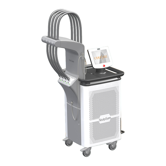
Chapter 4 System Description Components This section of the manual describes the main components of the SculpSure Laser including the delivery system. The SculpSure touch screen Display controls the settings. All Laser components are described in the following pages of this chapter. - Page 30 Components, continued Arm (umbilical management system) Display (270° swivel) Handle USB ports Dock Remote interlock Keyswitch Power button (circuit breaker) Power cord Casters (positional lock) Casters (locking) 850-7026-000 Rev 6 SculpSure by Cynosure Page 30 of 102 ®...
- Page 31 The USB ports are for PAC Keys, software updates, upgrades, and other data management functions. Power Button The Power Button must be turned on to operate the SculpSure System. The circuit breaker can be reset here. Power Cord The Power Cord carries electrical current from an appropriate wall outlet to the SculpSure Laser System.
- Page 32 Applied Parts of SculpSure Applicator Applicator Sapphire 850-7026-000 Rev 6 SculpSure by Cynosure Page 32 of 102 ®...
- Page 33 Frames (sold in multiples) P/N 100-7026-133 P/N 100-7026-134 P/N 100-7026-135 P/N 100-7026-136 P/N 100-7026-137 P/N 100-7026-138 P/N 100-7026-139 Bridge Connectors P/N 130-7026-116 Package of eight (8) 850-7026-000 Rev 6 SculpSure by Cynosure Page 33 of 102 ®...
- Page 34 Belts (sold in multiples) Single Belt P/N 100-7026-144 Single Belt, Short, P/N 100-7026-146 Triple Belt P/N 100-7026-145 850-7026-000 Rev 6 SculpSure by Cynosure Page 34 of 102 ®...
-
Page 35: Delivery System
Various Frames and Belts are available, depending on the operator’s configuration preference and client treatment area. Pager System The pager system is an accessory to SculpSure. The pager system is comprised of two components, the transmitter and the pager. Cynosure service technicians will link the pager to the transmitter. Transmitter The transmitter is intended to be used by the client for non-emergency contact to the treatment staff. -
Page 36: Pac Key
100 PACs, and one (1) PAC is consumed per Applicator in use. With SculpSure, the operator has the option to use 1, 2, 3, or 4 Applicators per treatment session. As such, 1, 2, 3 or 4 PACs will be consumed, respectively. -
Page 37: Pause Button
Pause Button The SculpSure system is equipped with a pause button, as described in Chapter 4. Pause button plugs into system as shown. Pause button may be hung on the Arm when not in use. Keep pause button within easy client access during treatment. -
Page 38: Applicators: How To Remove, How To Attach
Applicator. Removing an Applicator STEP 1. Unplug the system from the AC power outlet. Lock the two Locking Casters. STEP 2. Lift and remove the console cover. 850-7026-000 Rev 6 SculpSure by Cynosure Page 38 of 102 ®... - Page 39 A=Female Coolant, B=Male Coolant, C=Electrical, and D=Laser Fiber. IMPORTANT! If an Applicator is removed from the System and is not replaced, install the System Fiber Cap in the opening as shown (F). 850-7026-000 Rev 6 SculpSure by Cynosure Page 39 of 102 ®...
- Page 40 Immediately cap the Fiber end with the attached Fiber Cap as shown. Ensure the Cap is snug. If the Fiber end becomes soiled, contact Customer Service before using the laser. 850-7026-000 Rev 6 SculpSure by Cynosure Page 40 of 102 ®...
- Page 41 Wipe any visible Fluid, then discard paper towel. STEP 9. Remove Umbilical Housing by grasping the Housing and pulling it off, using a slight up and down rocking motion. 850-7026-000 Rev 6 SculpSure by Cynosure Page 41 of 102 ®...
- Page 42 STEP 11. With the Release Latch up, lift the Umbilical Roller, release the Latch, and gently disengage the Umbilical as shown. STEP 12. Loosen, do not remove, the twist knob. Turn the plate to vertical as shown. 850-7026-000 Rev 6 SculpSure by Cynosure Page 42 of 102 ®...
- Page 43 Block and pull away from the housing as shown. STEP 14. Pinch the two finger latches on the Applicator and release the Applicator from the Tray. Applicator removal process is complete. 850-7026-000 Rev 6 SculpSure by Cynosure Page 43 of 102 ®...
- Page 44 STEP 3. Push up on the Release Latch, lift the Umbilical Roller, release the Latch, and gently insert the Umbilical between the Rollers, as shown. 850-7026-000 Rev 6 SculpSure by Cynosure Page 44 of 102 ®...
- Page 45 STEP 7. Insert the Male Coolant connector. NOTE: It is normal for some Chiller Fluid to drip during insertion. Use a paper towel to wipe Fluid as required. Discard paper towel. 850-7026-000 Rev 6 SculpSure by Cynosure Page 45 of 102 ®...
- Page 46 NOTE: If the mechanism is locked and the Fitting won’t insert, press latch to disengage as shown. STEP 8. Insert the Female Coolant connector. NOTE: If mechanism is locked, press latch to disengage as shown. 850-7026-000 Rev 6 SculpSure by Cynosure Page 46 of 102 ®...
- Page 47 STEP 10. Carefully insert the Laser Fiber without touching the Fiber end. If the Fiber end becomes soiled, contact Customer Service before using the laser. STEP 11. Insert the Electrical Connector. 850-7026-000 Rev 6 SculpSure by Cynosure Page 47 of 102 ®...
- Page 48 STEP 12. Ensure all fittings are in place. STEP 13. Install Umbilical Cover. STEP 14. Install Console Cover. Applicator Installation is complete. 850-7026-000 Rev 6 SculpSure by Cynosure Page 48 of 102 ®...
-
Page 49: Chapter 5 Software Description
Chapter 5 Software Description This section of the manual describes the software screens and screen elements. Consult SculpSure Clinical Reference Guide for details on the proper use of the Applicators, Belts, Frames and treating the client. 850-7026-000 Rev 6 SculpSure... -
Page 50: Common Icons And Buttons
Common Icons and Buttons Standby. Start. Stop. Shopping cart Timer toggle. Advance-to-cool. indicates number of PACs available. Consult Operator’s Back. Tools. Manual. 850-7026-000 Rev 6 SculpSure by Cynosure Page 50 of 102 ®... - Page 51 Remote access button. Press to allow remote service technician Cynosure Service access. access only. Cynosure access System diagnostics. only. For exporting binary log files to a USB memory stick. 850-7026-000 Rev 6 SculpSure by Cynosure Page 51 of 102 ®...
-
Page 52: Operations Screens
Build Sustain Progress Bars Operations Screens NOTE: Not all screens are shown. At start-up, the system performs an automatic self-test. 850-7026-000 Rev 6 SculpSure by Cynosure Page 52 of 102 ®... - Page 53 Select desired treatment area. Observe blue and white “Consult Operator’s Manual” icon at right of screen. Only treat areas that are in the Indications For Use section of this Manual. 850-7026-000 Rev 6 SculpSure by Cynosure Page 53 of 102...
- Page 54 Applicator has been removed from the dock as indicated by a solid yellow rectangle with a flashing yellow border. Applicator is in the process of being installed into a Frame. 850-7026-000 Rev 6 SculpSure by Cynosure Page 54 of 102...
- Page 55 Before starting treatment, the operator must ensure all chosen Applicators are in proper contact with the skin. The next screen in this manual demonstrates proper contact of two Applicators. 850-7026-000 Rev 6 SculpSure by Cynosure Page 55 of 102...
- Page 56 Do not attempt to add a docked Applicator to the treatment site after treatment has started. The system will automatically disable that Applicator and an X will display in its position on the screen. 850-7026-000 Rev 6 SculpSure by Cynosure Page 56 of 102...
- Page 57 Note the progress bars, which appear above the timer. Treatment has started and is 13 seconds into the 4-minute Build mode. Upper right button is now Stop. Press Toggle to change from time elapsed to time remaining. 850-7026-000 Rev 6 SculpSure by Cynosure Page 57 of 102...
- Page 58 40 seconds of skin cooling (31 seconds elapsed is shown as cooling is in progress). Once cooling is completed, the system will prompt the user to press the Start button at top right. 850-7026-000 Rev 6 SculpSure by Cynosure Page 58 of 102...
-
Page 59: To Terminate Treatment
(two) minutes or longer in Sustain mode. If treatment is terminated prior to 2 (two) minutes in Sustain mode, PACs in use will be available for future use. The System will allow up to 2 (two) early terminations before consuming an Applicator’s PAC usage count. 850-7026-000 Rev 6 SculpSure by Cynosure Page 59 of 102... -
Page 60: Loss Of Contact
“Press the start button to resume treatment” message will appear on the screen. The operator must press the start button when it appears in the upper right of the screen. 850-7026-000 Rev 6 SculpSure by Cynosure Page 60 of 102 ®... -
Page 61: Treatment In Sustain Mode After Loss Of Contact
System will continue in Sustain mode to complete the remainder of the 21 minutes of treatment. Note that Build progress bar is now gray (inactive). 850-7026-000 Rev 6 SculpSure by Cynosure Page 61 of 102 ®... -
Page 62: To Link And Unlink Applicators
Next select the link / unlink button, near the bottom of the screen. Then select the back button. NOTE: Software version in upper right corner may vary from system to system. 850-7026-000 Rev 6 SculpSure by Cynosure Page 62 of 102... - Page 63 That Applicator’s blue shade signifies it is now unlinked, and its energy may now be adjusted independently of the other Applicators. Observe the “Applicator’s are unlinked” symbol on the top left of the screen. Note that the remaining Applicators remain linked to each other. 850-7026-000 Rev 6 SculpSure by Cynosure Page 63 of 102 ®...
- Page 64 To unlink a second Applicator, simply touch inside the Applicator’s center box and it will turn blue. That Applicator’s energy can now be independently adjusted as well. To restore the link, simply touch the unlinked Applicators’ center boxes. This will allow for synchronized adjustment. 850-7026-000 Rev 6 SculpSure by Cynosure Page 64 of 102 ®...
-
Page 65: To Lock The System
To Lock the System Operators should be familiar with SculpSure’s system locking feature. The system lock prohibits any on-screen adjustments until a PIN (Personal Identification Number) is entered. The system lock is optional. Unless the operator locks it, the system will be unlocked. - Page 66 “ENTER NEW PIN”). Keypad is now active. Set the new desired PIN. There is a one (1) character minimum PIN. Next select the check box, then select the Back button. 850-7026-000 Rev 6 SculpSure by Cynosure Page 66 of 102...
-
Page 67: To Verify The Current Pin
For a reminder of the current PIN, follow the first few steps of “To Change a PIN” section. The current PIN will appear in the ENTER NEW PIN box. Use the back button to back out of the screen, with no changes being made. 850-7026-000 Rev 6 SculpSure by Cynosure Page 67 of 102... -
Page 68: To Change Onscreen Languages
To view and/or select the languages supported by the System, select the Tools icon, then press System Settings. Next click the language selector menu. Select the language of choice. English is shown. 850-7026-000 Rev 6 SculpSure by Cynosure Page 68 of 102... -
Page 69: Chapter 6 System Specifications
Applicator Method of Optical Output Applicator Contact Window Cooling 13 - 16° C @ max. Irradiance and at a Temperature steady state Distilled water or Cynosure Chiller Fluid System Coolant Contact sensors on Applicator Actuator Beam Divergence 92° Nominal Ocular Hazard Distance (NOHD) - Page 70 This page has been intentionally left blank 850-7026-000 Rev 6 SculpSure by Cynosure Page 70 of 102 ®...
-
Page 71: Chapter 7 Laser Operation
Ensure power switch is in OFF position ( Plug prong end of power cord into an appropriate wall outlet. NOTE: Do not position the SculpSure Laser System such that it is difficult to disconnect the mains connection. NOTE: International customers—voltage requirements vary per region. Check with your Distributor for details. -
Page 72: Setting Treatment Parameters
Setting Treatment Parameters 1. Consult the SculpSure Clinical Guide for treatment information. 2. From the treatment screen, the up and down arrows may be used to select the desired Build and Sustain energy levels. 3. Press the standby/ready button to change the system from standby to ready mode, and to begin treatment. -
Page 73: Chapter 8 Maintenance
The section also provides troubleshooting information. ® The SculpSure Laser is designed to be professionally serviced at Cynosure , but some maintenance may be done in the field. In the event of a system failure, the system and/or ®... -
Page 74: Air Filter Maintenance
Air Filter Maintenance SculpSure has two (2) air filters, located on the bottom left and right of the system. Both air filters should be inspected and cleaned with a vacuum every 3-6 months. The air filters should be replaced annually. -
Page 75: Adding Coolant
Adding Coolant Periodically, the system requires coolant to be added to the coolant reservoir. A screen prompt will indicate low fluid. Add either distilled water or Cynosure Chiller Fluid only. Turn off the SculpSure System. Open the access door by pushing on the indentation, as shown at right. - Page 76 Add the distilled water or Chiller Fluid only. Twist the cap back onto the fill port, close the reservoir access panel, secure screw and close the access door by pushing on the indentation. 850-7026-000 Rev 6 SculpSure by Cynosure Page 76 of 102 ®...
-
Page 77: Care And Handling: System Exterior
Care and Handling: System Exterior Cynosure suggests that operators periodically clean the exterior of the laser system. Always turn off the system before cleaning. When cleaning, wear protective clothing and eyewear according to the cleaner manufacturer’s instructions. Cleaning System Exterior, Umbilical, and Dock (non-client contacting parts). - Page 78 Repeat the cleaning process if necessary. 4. Allow Applicator surfaces to dry completely before use by either air-drying or with a lint-free tissue. 850-7026-000 Rev 6 SculpSure by Cynosure Page 78 of 102 ®...
-
Page 79: Power Verification
Console calibration fixture 706-7026-027 with 807-7026-010 fiber Coolant jumper 706-7026-018 to check diode output Procedure Set the SculpSure applicator under test into the Cynosure power meter fixture assembly 2. Set the following Ophir meter parameters: 2.1. Set to read Power in the 100W range, 2.2. -
Page 80: Troubleshooting
Troubleshooting Faults Occasionally, the SculpSure system will encounter a fault, and the fault will display on the screen as shown in the examples on the following pages. While the fault graphic is on the screen, operator control of the system is suspended until action is taken. The appropriate action is communicated with onscreen prompts. - Page 81 If the F303 Fault occurs, allow system to cool and press the retry button. If problem persists, the customer should call Cynosure Service. The Service button seen on the screen is for the service technician to utilize, not the customer.
-
Page 82: Fault Codes, Descriptions, And Possible User Actions
If problem persists, call Service. Continue to operate without the disabled applicator, or restart the system using F409 Applicator 2 Contact Open the key. If problem persists, call Service. 850-7026-000 Rev 6 SculpSure by Cynosure Page 82 of 102 ®... - Page 83 Retry, or Disable faulty Applicator and continue. If problem persists, call Service. F507 Laser Diode 4 Energy Out Of Range High Retry, or Disable faulty Applicator and continue. If problem persists, call Service. 850-7026-000 Rev 6 SculpSure by Cynosure Page 83 of 102 ®...
- Page 84 Power Setting Out Of Range Retry. If problem persists, call Service. F120104 System Calibration Required. Call Service. Continue the treatment. F120105 PWM Calculation Out Of Range. Retry. If problem persists, call Service. 850-7026-000 Rev 6 SculpSure by Cynosure Page 84 of 102 ®...
- Page 85 Retry, or Disable faulty Applicator and continue. If problem persists, call Service. F120421 Laser Diode 4 FOM Out of Range Retry, or Disable faulty Applicator and continue. If problem persists, call Service. 850-7026-000 Rev 6 SculpSure by Cynosure Page 85 of 102 ®...
- Page 86 Chiller Manifold Temperature Sensor Shorted Restart the system using the key. If problem persists, call Service. (F115) F130208 ADC Test Failed Restart the system using the key. If problem persists, call Service. 850-7026-000 Rev 6 SculpSure by Cynosure Page 86 of 102 ®...
- Page 87 (F411) the key. If problem persists, call Service. F140220 Clean contact pads. Retry, or Disable faulty Applicator and continue. If problem Applicator 1 Contact Shorted (F508) persists, call Service. 850-7026-000 Rev 6 SculpSure by Cynosure Page 87 of 102 ®...
- Page 88 Retry, or Disable faulty Applicator and continue. If problem persists, call Service. (F516) F170202 Chiller Valve 2 No Flow When Expected Retry, or Disable faulty Applicator and continue. If problem persists, call Service. (F517) 850-7026-000 Rev 6 SculpSure by Cynosure Page 88 of 102 ®...
- Page 89 Restart the system using the key. If problem persists, call Service. (F120) F180102 Coolant Low Add coolant to Heat Exchanger tank and retry. If problem persists, call Service. (F309) F180201 Battery Low Continue the treatment. 850-7026-000 Rev 6 SculpSure by Cynosure Page 89 of 102 ®...
- Page 90 The laser was overfilled with distilled water and will continue to drain out over several sessions. Water leaking from system There is an internal system leak. Call service. with persistent “Add water” faults. 850-7026-000 Rev 6 SculpSure by Cynosure Page 90 of 102 ®...
-
Page 91: Chapter 9 Customer Support
Cynosure has the sole responsibility to determine the cause of merchandise defect. Installation Cynosure or its authorized personnel installs the laser, gives a demonstration of operation, and provides a basic training service for each new customer. 850-7026-000 Rev 6 SculpSure... -
Page 92: Customer Service
Service personnel make periodic safety checks and functional evaluations as a part of maintenance. Contacting Customer Service If there is a technical problem with the laser, contact the Cynosure Service Department. Technical support Call: 1-888-523-2233 or 1-978-256-8760 Fax: 1-978-349-6152 or 1-978-256-4888 Email: service@cynosure.com... -
Page 93: Appendix A Service Procedures
IMPORTANT: This appendix contains procedures that should only be performed by authorized service personnel. NOTE: Do not perform service on the SculpSure laser system while in use with the client. System Battery Replacement NOTE: Replace with Panasonic CR2032, 3V, Lithium, coin battery. -
Page 94: Fuse Replacement
8.0A, SPT 5 mm x 20 mm IEC Standard Fuse Cables The following table lists cables used on the system. Cable Name Cable Length Shielding Notes AC Line Cord 3.4 m 850-7026-000 Rev 6 SculpSure by Cynosure Page 94 of 102 ®... -
Page 95: External Laser Calibration
Plug in the USB end of the 601-7026-000 cable into the USB port on the back of the SculpSure system. Turn the SculpSure system ON and the system will go through self check when it comes to the standby screen, go to the Utilities button and click on the Service icon. - Page 96 This page has been intentionally left blank 850-7026-000 Rev 6 SculpSure by Cynosure Page 96 of 102 ®...
-
Page 97: Appendix B Emc Declaration
EMC Declaration Guidance and manufacturer’s declaration- electromagnetic emissions The SculpSure is intended for use in the electromagnetic environment specified below. The customer or the user of the equipment should assure that it is used in such an environment Emission Test... - Page 98 Guidance and manufacturer’s declaration- electromagnetic immunity The SculpSure system is intended for use in the electromagnetic environment specified below. The customer or the user of the equipment should assure that it is used in such an environment Immunity test IEC 60601...
- Page 99 Guidance and manufacturer’s declaration- electromagnetic immunity SculpSure is intended for use in the electromagnetic environment specified below. The customer or the user of the equipment should assure that it is used in such an environment. Immunity test IEC 60601 Compliance level...
- Page 100 Recommended separation distances between portable and mobile RF communications equipment and the Cynosure SculpSure. The SculpSure system is intended for use in an electromagnetic environment in which radiated RF disturbances are controlled. The customer or the user of the SculpSure can help prevent electromagnetic interferences by maintaining a minimum distance between the portable and mobile RF communications equipment (transmitters) and the SculpSure as recommended below, according to the maximum output power of the communications equipment.
- Page 101 850-7026-000 Rev 6 SculpSure by Cynosure Page 101 of 102 ®...
- Page 102 850-7026-000 Rev 6 SculpSure by Cynosure Page 102 of 102 ®...
Need help?
Do you have a question about the SculpSure and is the answer not in the manual?
Questions and answers