Advertisement
Quick Links
Technical Support: 1-800-815-2258
Introduction to the RF Gateway
This instructional leaflet contains the field
installation, configuration, and maintenance
instructions for the Cooper Power Systems RF
Gateway.
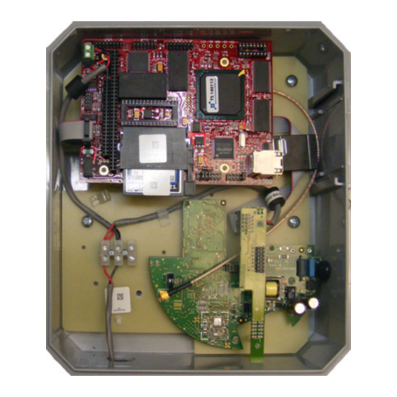
The RF Gateway is a reliable and secure
bi-directional interface between the back office
network and nodes on the Cooper Power Systems
RF mesh network. The Gateway is compatible with
standard communication protocols and hardware,
such as cellular, DSL, fiber and private backhaul. The
Gateway automatically networks and collects
information from the nodes and is ideal for AMI and
sub-metering applications.
The RF Gateway can be installed on utility poles,
building exteriors, or telecommunication equipment
rooms. The following procedures describe the how
to install a Gateway in a communications cabinet,
which includes a UPS battery backup, and how to
install the Gateway/communications cabinet and an
antenna on a utility pole:
•
"Installing the Gateway within a
Communications Cabinet" on page 5
•
"Installing the Gateway/Communications
Cabinet on a Utility Pole" on page 6
•
"Installing the Antenna on a Utility Pole" on
page 7
•
"Configuring the Gateway" on page 8
•
"Verifying Backhaul Communications" on
page 9
WARNING Dangerous voltages are present. Equipment damage, personal injury, and death can result
if safety precautions are not followed. Use authorized utility procedures to install, test, and service the
Gateway.
The features of the Gateway are:
•
Fully self-configuring wireless mesh network.
•
Fully bi-directional interface between RF mesh
network and the back office.
•
Integrates gas and water meters with electric
meters on one network.
•
Fail-over protection between Gateways.
•
Operates in the 915 MHz license-free band.
•
Highly secure authentication, key generation and
encryption with all Nodes.
•
Contains local storage for 45 days of interval data
for each Node.
•
Automatic data recovery and gap filling.
•
Configurable access control.
•
NEMA-4 enclosure available.
RF Gateway
Brazil
Instructional Leaflet
Advertisement

Summary of Contents for Cooper RF
- Page 1 • Configurable access control. • NEMA-4 enclosure available. The RF Gateway can be installed on utility poles, building exteriors, or telecommunication equipment rooms. The following procedures describe the how to install a Gateway in a communications cabinet, which includes a UPS battery backup, and how to...
- Page 2 FOR LIFE FOR LIFE Cooper Power Systems™ products meet or exceed all applicable industry standards relating to product safety. We actively promote safe practices in the use and maintenance of our products through our service literature, instructional training programs, and the continuous efforts of all Cooper Power Systems employees involved in product design, manufacture, marketing, and service.
- Page 3 WARNING The installer of this radio equipment must ensure that the antenna is located or pointed such that it does not emit RF field in excess of Health Canada limits for the general population; consult Safety Code 6, obtainable from Health Canada’s Web site: www.hc-sc.gc.ca.
- Page 4 WARNING The installer of this radio equipment must ensure that the antenna is located or pointed such that it does not emit RF field in excess of Health Canada limits for the general population; consult Safety Code 6, obtainable from Health Canada’s Web site: www.hc-sc.gc.ca.
- Page 5 Charger the right. 11. Connect an Ethernet cable from the AC Power Wires from Power communication equipment to the Ethernet Terminal Screws Battery Charger Supply port in the Gateway. Cooper Power Systems...
- Page 6 RF Gateway (Brazil) Installing the Gateway/Communications Cabinet on a Utility Pole The following installation requirements are 4. Install a lag screw into the utility pole and hang recommended when installing the the Gateway/communications cabinet using Gateway/communications cabinet on a utility pole: the center hole of the mounting hardware on the top of the communications cabinet.
- Page 7 1. Mount the antenna to the top of the utility pole Gateway/communications cabinet and verify using authorized utility procedures. that the hardware in the communications NOTE Cooper Power Systems recommends cabinet powers up successfully. mounting the antenna at least three feet WARNING Dangerous voltages are present.
- Page 8 RF Gateway (Brazil) Configuring the Gateway Complete the following steps to configure the 10. Tap the Save button to save the changes to the Compact Flash (CF) memory card that is installed in compact flash card. A confirmation dialog box is the Gateway: displayed when the information is saved.
- Page 9 Close and secure the door of the communications cabinet. c. Contact Customer Support to have them assign a unique network setting to the Gateway. d. Add the Gateway to the RF mesh system using the Network Manager software. Gateway Specifications Application Radio Communications (900 MHz)
-
Page 10: Fcc Compliance Statement
• Consult the dealer or an experienced radio/TV technician for help. These devices operate under Part 15 of the FCC rules. Modifications to these devices not expressly authorized by Cooper Power Systems may affect your ability to legally operate these devices.


Need help?
Do you have a question about the RF and is the answer not in the manual?
Questions and answers