Table of Contents
Advertisement
Quick Links
Advertisement
Table of Contents

Related Manuals for Chandler Systems D15


Summary of Contents for Chandler Systems D15
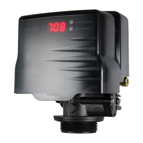
- Page 1 D15 - Control Valve...
- Page 2 Chandler Systems...
-
Page 3: Table Of Contents
Dow Corning® silicone grease be used as a lubricant for all control valves. Dow Corning® 7 Release Compound is used in the manufacture of Chandler Systems control valves. (Part # LT-150) Sealants Pipe dope and liquid thread sealers may contain a carrier that attacks some plastic materials. It is recommended that only Teflon®... -
Page 4: Valves Specifications
Chandler Systems Valve Control Board Connections Valve specifications Valve Specifications Valve Material Noryl®* Inlet / Outlet 3/4” - 1” Cycles Flow Rates (50 psi inlet) - Valve Alone Continuous (15 psi drop) 21 gpm Peak (25 psi drop) 27 gpm CV (flow at 1 psi drop) Max. - Page 5 Legacy View Control Start Up Legacy View Control When you download the Legacy View app and open it, you will see a screen similar to this one. Any Legacy View bluetooth compatible device will appear here as long as it is within range and you have bluetooth enabled on your phone or tab- let.
- Page 6 Chandler Systems Legacy View Control Filters Softeners 1. Current time on the system. Tap the box to set the time to that of the devices 2. Shows battery life of attached 9v backup battery a. Softeners: Shows current water flow b.
- Page 7 Advanced Settings The Advance Settings page is where cycle times and certain other settings can be adjust- ed. To get there simply click on the three lines in the top left hand corner to bring up the side menu and just tap on Advance Settings button.
-
Page 8: Advance Settings
Chandler Systems Advanced Settings - Softener 1. Days left until next regeneration based on Regeneration Day Over- ride 2. Amount of days between regeneration can set between 0-29. Set ting at 0 turns this feature off 3. Percentage of soft water saved in case system runs out before next regeneration time 4. -
Page 9: Status History
Status and History The Status and History page under the side menu gives a more detailed account of how much water is actually being used. 1. Amount of water flowing through system currently 2. Total gallons treated since system was installed 3. - Page 10 Chandler Systems App Salt Monitoring Update The recent release of Legacy View, version 3.1.18, adds Salt Monitoring to the existing generation of residential and commercial metered softeners that are running the C4.22 firmware. Below is an overview of the new func- tionality.
-
Page 11: Salt Monitoring Update
When the salt level is set the brine tank level on the dash- board will update to show a smaller representation of the brine tank with the current salt level. When the softener completes a regeneration the salt level will be updated accordingly. - Page 12 Chandler Systems Once enabled, a notification is created that can’t be dis- missed until you disable the salt monitoring. This notifi- cation is a service that runs in the background and will trigger a Bluetooth scan every 30 minutes, as mentioned above.
- Page 13 Scroll down until you see Legacy View and tap that to select it. From here, you can click and drag the widget to the home screen or click the “Add Widget” button. This will place it on the home screen, and it will initiate an initial scan.
- Page 14 Chandler Systems Once setup, the widget will trigger a Bluetooth scan every 30 minutes, as mentioned above. If all softeners are reporting as having adequate salt levels, then it will display “Salt Level OK”. If a softener is reporting that it has low salt, then “Salt Level Low”...
- Page 15 Main Menu / Button Control 1. To enter main menu press the Menu/Enter button (Time of Day will Flash) 2. To set time of day press the Set/Change button (First digit will begin to flash) -To change digit value press the Set/Change button multiple times and then press the Menu button to adjust the next digit - (Next digit will flash)
-
Page 16: Main Menu
Chandler Systems Main Menu 5. (Filter Version) Set the Regeneration Frequency -To change digit value press the Set/Change button mult iple times and then press the Menu Button to adjust the next digit -Once the last digit is accepted all digits will flash... -
Page 17: Normal Operation
Normal Operation 1. (Metered Version) -Normal Display Alternates Between Time of Day and Gallons of Treated Water Remaining. -When the display is Showing Gallons Remaining and there is Water Flow the Upper Colon Lights will Flash. -As Treated Water is Used the Gallons Remaining Display will Count Down from a Maximum Value to 0. -Once the Count Reaches 0 a Regeneration Cycle will be Initiated at the Next Designated Regeneration Time. - Page 18 Chandler Systems 2. (Filter/Aeration Version) -Normal Display Alternates Between Time of Day and Days Until Regeneration. -Days Remaining Until the Next Regeneration will Count Down from the Regeneration Day Override Value to 1 Day Remaining. -Once the Count Reaches 1 a Regeneration is Initiated at the Next Designated Regeneration Time.
- Page 19 Normal Operation 1. Battery Back-Up (This unit uses a standard 9 volt alkaline battery) -Installing the battery -The control valves have a battery wire that hangs down from the control board into the battery tray -From there, let the battery just sit in the tray -Features of battery back-up -Maintains the time of day during power failures.
-
Page 20: Master Programming Mode
Chandler Systems Master Programming Mode Entering Master Programming Mode -To Enter Master Programming Mode Press and Hold both buttons for 5 seconds. Note: All Master Programming functions have been preset at the factory. Unless a change is desired it is NOT necessary to enter the Master Programming Mode. - Page 21 Regeneration Cycle Step Programming Press the Menu/Enter Button. The next 4 displays viewed are part of a series of ption settings used to program the Regeneration Cycle. Each display is used to set the duration time in minutes for that specif- ic step in a regeneration cycle.
- Page 22 Chandler Systems Bluetooth Capability (bE 1) Press the Menu/Enter button. This display is used to turn the bluetooth capabilities of the system on (1) or off (0). The system should always be on regardless of it’s usage. If a connection to system cannot be made, verify this setting is turned on.
-
Page 23: Filter Master Programming
Filter Master Programming Regeneration Time (r) After pressing the Menu/Enter and Set/Change button, the display shows the option setting for Regeneration Time. It is identified by the letter ‘r’ in the left digit. Set the desired time of day that a regeneration may occur, if required. - Page 24 Chandler Systems Bluetooth Capability (bE 1) Press the Menu/Enter Button. This display is used to turn the bluetooth capabilities of the system on (1) or off (0). The sys- tem should always be on regardless of it’s usage. If a connection to system cannot be made, verify this setting is turned on.
- Page 25 Aeration Filter Master Programming Regeneration Time (r) After pressing the Menu/Enter and Set/Change Button, the display shows the option setting for Regenera- tion Time. It is identified by the letter ‘r’ in the left digit. Set the desired time of day that a regeneration may occur, if required.
- Page 26 Chandler Systems Pulse Chlorine Setting (J 02) - Side Mount Aeration Valve Only Press the Menu/Enter Button. This display shows how much chlorine will be injected into the system if the system is designed for it. This is mainly used for Side Aeration valves.
- Page 27 Bluetooth Password (btPP) Press the Menu/Enter Button. The Next display shown is the Bluetooth Password (btPP). When shown, this num- ber will flash between “btPP” and a four digit code. The code is used for accessing the Legacy View app. The default is “1234” and unless it has been changed, no password will be needed to access the control valve with Legacy View.
- Page 28 Chandler Systems CABINET SOFTENER POWER HEAD ASSEMBLY Part No. 20016X002 20001X007 20016X101 21001X120 20016X002 20016X006 Motor Power Flow Meter 20001X122 SC10 20001X127 20016X108 Motor Power Flow Meter DESCRIPTION PART NO Front Plate 20016X001 Encoder Wheel 20001X007 Cabinet Legacy Board As-...
- Page 29 CABINET SOFTENER BODY ASSEMBLY 21/22 DESCRIPTION PART NO DESCRIPTION PART NO Injector Cap Screw 20001X226 Piston Assembly 20001X231 Injector Cap 20001X223 Screw 20001X001 Injector Seal 20001X224 Seal & Spacer Kit 20561X253 Injector - White 20017X219 Bottom Spacer 20001X234 Screen 20001X222 DLFC Button 2.0 20251X267 Plug...
- Page 30 Chandler Systems SOFTENER VALVE DESCRIPTION PART NO. Piston Assembly 20001X231 10-24 X 3/4” Screw SST 20001X001 Seal and Spacer Kit 20561X253 End Spacer 20001X234 Flow Control Button 1.5 20251X266 Flow Control Button 2.0 20251X267 Flow Control Button 2.4 20251X268 DLFC Assy.
- Page 31 SOFTENER POWERHEAD LETTERS IN DIAGRAM REPRESENT WIRING CONNECTIONS DESCRIPTION PART NO. Metered Power Head Assy. 21003X100 Softener Circuit Boad Assy. 22003X102 Encoder 20001X124 Front Plate 20001X004 Encoder Wheel 20001X007 Main Gear 21001X120 Power Supply 20001X125 Back Plate 20001X005 Lower Front Base For Cover 20111X002 Legacy View Motor Assy.
- Page 32 Chandler Systems FILTER VALVE DESCRIPTION PART NO. Piston Assembly 20001X231 10-24 X 3/4” Screw SST 20001X001 Seal and Spacer Kit Incl 20561X253 (5) #3 & (4) #4 End Spacer 20001X234 Flow Control Button 5.0 20251X272 Flow Control Button 7.0 20251X273 DLFC Assy.
- Page 33 FILTER POWERHEAD LETTERS IN DIAGRAM REPRESENT WIRING CONNECTIONS DESCRIPTION PART NO. Power Head Assy. 21002X100 Filter Circuit Boad Assy. 21002X101 Encoder 20001X124 Front Plate 20001X004 Encoder Wheel 20001X007 Main Gear 21001X120 Power Supply 20001X125 Back Plate 20001X005 Lower Front Base For Cover 20111X002 Motor 20016X006...
- Page 34 Chandler Systems AERATION VALVE...
- Page 35 AERATION VALVE DESCRIPTION PART NO. Final Rinse Piston Assembly 20009X231 10-24 X 3/4” Screw SST 20001X001 Seal and Spacer Kit Incl (5) #3 & (4) #4 20561X253 End Spacer 20001X234 Flow Control Button 5.0 GPM 20251X272 Flow Control Button 7.0 GPM 20251X273 DLFC Housing 20017X251...
- Page 36 Chandler Systems AERATION POWERHEAD LETTERS IN DIAGRAM REPRESENT WIRING CONNECTIONS DESCRIPTION PART NO. Powerhead Assy. 20010X100 Circuit Board Assy. 20010X101 Encoder 20001X124 Front Plate 20001X004 Encoder Wheel 20001X007 Main Gear 21001X120 Power Supply 20001X125 Back Plate 20001X005 Lower Front Base For Cover...
-
Page 37: Side Valve Breakdown
SIDE VALVE AIR INJECTION ASSEMBLY (Located near base of tank) To Air Injection Assembly... - Page 38 Chandler Systems SIDE VALVE DESCRIPTION PART NO. Piston Assembly Final Rinse 20009X231 10-24 X 3/4” Screw SST 20001X001 Seal and Spacer Kit 20561X253 End Spacer 20001X234 Flow Control Button 5.0 GPM 20251X272 Flow Control Button 7.0 GPM 20251X273 DLFC Housing 20017X251 Drain Line Hose Barb 90 °...
- Page 39 SIDE POWERHEAD LETTERS IN DIAGRAM REPRESENT WIRING CONNECTIONS...
- Page 40 Chandler Systems SIDE POWERHEAD DESCRIPTION PART NO. Powerhead Assy. 20015X100 Circuit Board Assy. 22015X101 Encoder 20001X124 Front Plate 20001X004 Encoder Wheel 20001X007 Main Gear 21001X120 Power Supply 20001X125 Back Plate 20001X005 Lower Front Base For Cover 20111X002 Microswitch 20251X113 Switch Spacer...
-
Page 41: Bypass Assembly
BYPASS ASSEMBLY DESCRIPTION PART NO. D15 Bypass (included with all units) 20017X283 1” NPT Elbow Set (included with all units) 20017X284 1” Female Straight Slip Set (optional) 20017X288 1” NPT Straight Set (optional) 20017X289 3/4” NPT Straight Set (optional) 20017X307 1”... -
Page 42: Service Instructions
Chandler Systems SERVICE INSTRUCTIONS General Preliminary Instructions PERFORM BEFORE ALL SERVICING OPERATIONS 1. Turn off water supply to conditioner. -If the conditioner installation has a “three valve” bypass system, first open the valve in the bypass line, then close the valves at the conditioner inlet and outlet. -
Page 43: Error Codes
SERVICE INSTRUCTIONS To Replace Seals and Spacers 1. Follow steps A1 - A3. 2. Disconnect the meter signal wire from the circuit board. 3. Remove screw and washer at piston drive yoke. Remove powerhead mounting screws. The entire powerhead assembly will now lift off easily. Remove piston retaining plate screws. 4. -
Page 44: Troubleshooting
Chandler Systems TROUBLESHOOTING SYMPTOM PROBABLE CAUSE CORRECTION Power supply plugged into intermittent Connect to constant power source or dead power source Disconnected meter cable Reconnect cable 1. Softener Fails to Improper control valve programming Reset program settings Regenerate Automatically Defective power supply... -
Page 45: Valve Dimensions
VALVE DIMENSIONS... -
Page 46: Warranty
HOME, this warranty covers your water treatment equipment, prompt notice of any claim is given to an authorized if you are the first user of this Chandler Systems, Inc. water Chandler Systems or a designated contractor is provid- treatment equipment and purchased it for single family home use... - Page 48 Chandler Systems Inc. 710 Orange St, Ashland, OH 44805 l PH 419-281-6829 0622TV...
Need help?
Do you have a question about the D15 and is the answer not in the manual?
Questions and answers