Advertisement
Quick Links
Advertisement

Related Manuals for Chandler Systems Drop D-CPS


Summary of Contents for Chandler Systems Drop D-CPS
- Page 1 Installation Manual Commercial Protection Valve D-CPS Chandler Systems...
-
Page 2: Introduction
To further help you operate your new DROP system, we have provided you with many other resources for you to learn more. Feel free to call Chandler Systems when you need additional help. We also have many resources located on our website including instructional videos, and images. -
Page 3: Table Of Contents
TABLE OF CONTENTS Introduction....................2 Table of Contents..................How to Use Your System................4 Contents of Carton..................Precautions....................Installation Instructions................... The DROP Remote..................12 DROP Limited Warranty................CAUTION: • Do not locate unit where it will be subject to temperatures below freezing. •... -
Page 4: How To Use Your System
HOW TO USE YOUR SYSTEM Your DROP Commercial Protection System uses advanced technology to protect your facility from leaks, and save you money, all while providing years of trouble-free operation. Additional Features You’ll Find on Your DROP Home Protection System •... - Page 5 HOW TO USE YOUR SYSTEM Manually Bypassing Your System: The Commercial Protection System requires a bypass loop to be installed to allow the system to be taken in and out of service. To take your system out of service close the ball valve on the inlet side of the Motorized Valve and the ball valve on the outlet side of the Transducer Assembly.
-
Page 6: Contents Of Carton
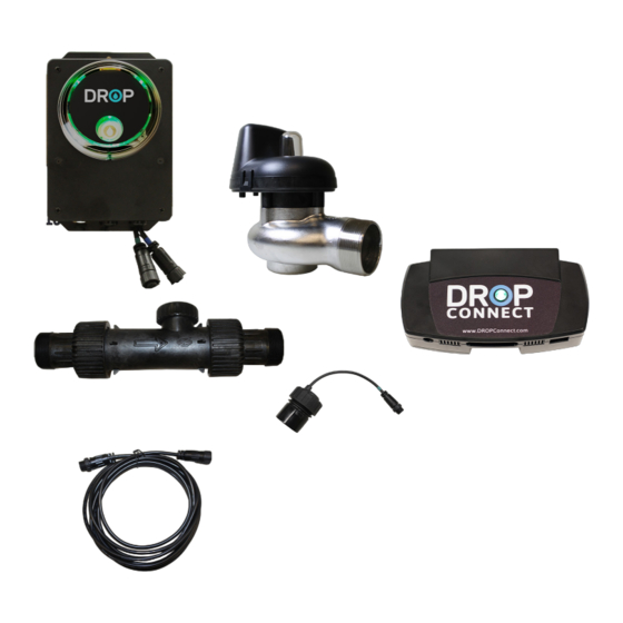
HOW TO USE YOUR SYSTEM Contents of Carton COMMERCIAL PROTECTION (Mounting Rack) CONTROL VALVE *Optional 1.5” NPT CONNECTORS MOTORIZED VALVE LEAK DETECTORS REMOTE 1.5”, 2” or 3” (Contains 2 or 4 and FLOW METER includes batteries) 1.5”, 2” or 3”... -
Page 7: Precautions
HOW TO USE YOUR SYSTEM Precautions Read Manual Ventilate Use Eye Protection Protect nearby materials when soldering Use only lead-free solder If existing plumbing is copper, install grounding strap before creating plumbing gaps. -
Page 8: Installation Instructions
INSTALLATION INSTRUCTIONS STEP 1: Plumb the system into your water supply Unpack equipment. Systems are sized for 1.5”, 2”, or 3” inlet / outlet. With the bypass loop in bypass position, turn on the main water supply. Open a cold soft water tap nearby and let run a few minutes or until the plumbing is free from foreign material (usually solder or debris from cutting the pipe) that may have resulted from the installation. - Page 9 INSTALLATION INSTRUCTIONS STEP 2: Download the DROP Connect Mobile STEP 3: Determine where you want to locate the HUB and REMOTE As shown above, all DROP devices that plug into 120 volt outlets expand the DROP Link mesh network. When placing the DROP Hub and Remote, keep in mind that installing them in separate areas of the facilty will expand the network.
- Page 10 INSTALLATION INSTRUCTIONS STEP 4: Follow Mobile Onboarding in the DROP Connect App See Users Guide for detailed instructions STEP 5: Add & Name Each Device See Users Guide for detailed instructions STEP 6: Install 9V Battery into your Hub & CPS Control Box 9 volt battery back up is recommended for DROP Hub.
- Page 11 INSTALLATION INSTRUCTIONS STEP 9: Configure the System The DASHBOARD provides a system information overview Set High and Low Temperature Notifications DEVICES > HOME PROTECTION VALVE > STATUS (Navigation description examples can be found in the User Guide) The DEVICES screen allow you to customize how your system operates.
-
Page 12: The Drop Remote
THE DROP REMOTE In addition to acting as a DROP Link mesh network extender, the DROP Remote has additional features: At a glance the remote can provide the status of your water system through color codes. Color codes for normal operation Water is in Service Water is Shutoff Slow blinking indicates you have a... - Page 13 SYSTEM NOTES...
- Page 14 Additional Terms & Conditions property, consequential mold damage, loss of profits, loss of savings What Chandler Systems Inc will do if you have a covered warranty claim; or revenue, loss of use of the products or any associated equipment, Chandler Systems Inc will at its discretion either make repairs to correct...
- Page 15 —Increase the separation between the equipment and receiver. —Connect the equipment into an outlet on a circuit different from that to which the receiver is connected. —Consult the dealer or an experienced radio/TV technician for help. Chandler Systems Inc. 710 Orange St. Ashland, OH 44805 P.
- Page 16 Copyright Chandler Systems Inc. DROP is a product of Chandler Systems Inc. All rights reserved. DROPCPS1121TV...
Need help?
Do you have a question about the Drop D-CPS and is the answer not in the manual?
Questions and answers