Advertisement
Quick Links
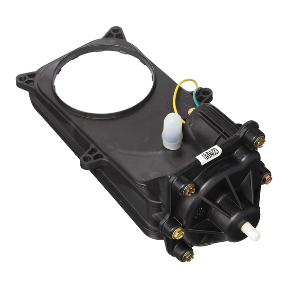
RV Toilet Service Parts for
Tools needed
•
Flat-blade screwdriver
•
Adjustable Wrench
•
Socket Wrench with 7/16" socket • Pliers
•
Silicone Grease
•
DAP Dynaflex Caulk or equivalent (available at most hardware stores)
Note:
•
Read all instructions before beginning work.
To Remove Toilet From Floor
1. Turn off RV water supply per RV Owner's Manual.
2. Press both keypad buttons at the same time, twice, to open blade and
drain bowl of water. If control or mechanism does not work, you will have
to open the valve manually. Remove the Sound Deadening Insulation
(if present) from the back of the mechanism to access the mechanism
lead screw (Fig. E). Turn knob (if present – otherwise use a 5/16" socket
wrench) clockwise to open the valve.
3. P r y o f f Bo l t Ca p s wi t h F l a t - b l a d e s c r e wd r i v e r . U s e
7/16-inch wrench to remove Lag Screws.
Fig. A
Switch
box
(not present
on all mod-
els)
4. Turn off power to Toilet at RV's DC distribution panel.
5. Tilt Toilet toward you to gain access to connections.
6. Disconnect Toilet's 12-volt power hookup to RV.
7. Disconnect Water Supply Line from elbow connector by hand. Use
Adjustable Wrench if necessary, with care.
8. Remove Toilet from floor and place upside down on towel or soft fabric
mat.
9. Remove old Closet Flange Seal (may be found on toilet or in floor at
Closet Flange). Discard.
10. Cover Holding Tank opening to contain odor.
To Remove Old Part
1. Using Screwdriver handle, tap out 2 Mounting Bushings (Fig. B). Save
them.
2. Remove Mounting Flange (Fig. B).
3. High Profile models only: If Extension Tube (Fig. C) did not come out
with Mounting Flange, remove it and the Extension Tube Seal. Save.
4. Remove and save 4 Mechanism Screws (MS, Fig. D).
5. Ease Mechanism Assembly off white Mechanism Plate. To get Mecha-
nism out, you may need to remove other parts (Fig. A). To remove Metal
Bracket, loosen screws and swing out. To remove Controller Assembly
and/or Switch Box, use a flat-bladed screwdriver to pry them from wall
of unit. Remove old adhesive pad(s).
Form #19632
Aria/Aria Deluxe
• Phillips Screwdriver
• Scraping tool
Metal Bracket
Controller As-
sembly
Motor Leads
Mechanism Assembly
Fig. B
Mounting Flange
Fig. C
Shown
separate for
clarity – these
items nor-
mally remain
assembled
newer plates have
a 2nd hole at front
Fig. D
Mechanism
6. Disconnect 2 (green/yellow) Wire Motor Leads from Mechanism As-
sembly (Fig. A). Use pliers if necessary.
7. Disconnect Overflow Tube if present (pre 3-16-03) from Mechanism
Assembly. Discard Mechanism if not returning.
Part #19613
Mounting Bushing
Mounting
Flange
Mounting
Flange Seal
Clamp
HIGH PRO-
Extension
FILE ONLY
Tube
Extension
Tube Seal
Mechanism
Tube Lip
Mechanism
White Mechanism Plate
Rev. 1/15/08
Advertisement

Subscribe to Our Youtube Channel
Related Manuals for Thetford 19613


Summary of Contents for Thetford 19613
- Page 1 Mechanism Assembly Part #19613 Aria/Aria Deluxe RV Toilet Service Parts for Tools needed Fig. B • Flat-blade screwdriver • Phillips Screwdriver • Adjustable Wrench • Scraping tool • Socket Wrench with 7/16” socket • Pliers • Silicone Grease • DAP Dynaflex Caulk or equivalent (available at most hardware stores) Mounting Flange Note: Mounting Bushing • Read all instructions before beginning work. Fig. C To Remove Toilet From Floor Mounting 1. Turn off RV water supply per RV Owner’s Manual.
- Page 2 Mechanism Assembly Part #19613 Page 2 8. Remove Blade Seal from white mechanism plate. Discard. Fig. E 9. Important: If your mechanism plate has two holes at front (dotted lines in Fig. D), AND no leakage is suspected at foam gasket area, you do not need to install the new plate provided in this kit. Skip down to the heading “To Blade Replace Mechanism.” Seal To remove Mechanism Plate, loosen the 3 Screws in well nuts (WN, Mechanism Fig. D) and pull the plate off the bowl. If well-nuts do not come out with Lead Screw the plate screws, either push them through to the interior or re-insert the screws to pull them out. Discard plate and well-nut hardware. Mechanism 10. Scrape off old Seal from china with sharp tool. Use mineral spirits or Plate alcohol to remove residue. To Replace Mechanism Plate (if it has been removed) 1. Apply a 1/4” wide continuous ring of caulk sealant around the top of the exposed side of the flat foam seal. (Fig. E).
Need help?
Do you have a question about the 19613 and is the answer not in the manual?
Questions and answers