Table of Contents
Advertisement
Quick Links
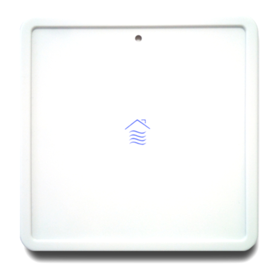
EP5000L air quality probe Installation manual
Ver
Date
V1
16/12/2019
V2
23/04/2021
V3
09/07/2021
V4
10/10/2021
123 rue de Bellevue, 92100 Boulogne Billancourt
Tél : 33-(0) 1 41 41 00 02 -
Modification / Update
Initial Version
Update
Disassembling the front panel
Add recommendations and warranty
France
www.nano-sense.com
page 1/8
Advertisement
Table of Contents

Related Manuals for NanoSense LoRa EP5000L


Summary of Contents for NanoSense LoRa EP5000L
- Page 1 123 rue de Bellevue, 92100 Boulogne Billancourt France Tél : 33-(0) 1 41 41 00 02 - www.nano-sense.com EP5000L air quality probe Installation manual Date Modification / Update 16/12/2019 Initial Version 23/04/2021 Update 09/07/2021 Disassembling the front panel 10/10/2021 Add recommendations and warranty page 1/8...
-
Page 2: Table Of Contents
Installation Guide Modbus E5000 IAQ probe Summary SECURITY ....................................3 POSITIONING ..................................3 DISASSEMBLING THE FRONT PANEL ............................5 FLUSH MOUNTING .................................. 5 SURFACE BOX MOUNTING (RENOVATION) ..........................5 WIRING ....................................5 INSTALLATION ..................................6 CONNECTIONS ..................................6 POWER ON ....................................6 NFC ...................................... -
Page 3: Security
Installation Guide Modbus E5000 IAQ probe 1. Security WARNING Danger of death, risk of electric shock and fire! The installation should only be undertaken by a qualified electrician! To apply for correct bus and power cables and to activate the device, comply with the state of the art and standards. - Page 4 Installation Guide Modbus E5000 IAQ probe The following graph shows how the different contributions of natural light combine without even taking into account the generally zenithal artificial lighting: Consideration should also be given to the receptivity of the light sensor which is mounted vertically similar to our eyes: Any work not in accordance with this documentation or changes to the device will invalidate all warranty claims.
-
Page 5: Disassembling The Front Panel
Installation Guide Modbus E5000 IAQ probe 3. Disassembling the front panel The front panel is clipped on the apparatus. Put the probe on a table, the front glass facing the table (connector up) With your fingernails or your finger move away one clip of the front panel peripheral from the apparatus and pull the apparatus Do not spread the outline too far and do not exert pressure on the glass with your hand or other means as this may disassemble the... -
Page 6: Installation
Installation Guide Modbus E5000 IAQ probe from which the duct passes through. If the case crosses through the sealing plane (plasterboard), seal between the casing and panel with a special sealant without silicone and VOC. Connectors are specified for rigid cable 18 to 24 AWG (1 to 0.5mm dia.) or twisted 20 to 22 AWG (0.8 to 0.65mm dia.) The connectors accept two 0.8mm cables on the same terminal in order to chain several sensors. -
Page 7: 10. Nfc
Installation Guide Modbus E5000 IAQ probe LED code on the front panel Identification # Defective FRU Power supply failure suspected or No LED active probe power supply board Red LED on for 5 seconds Followed by a yellow flash Front panel board. Followed by 2 yellow flashes Single band CO2 sensor module. -
Page 8: 12. Disconnection
Installation Guide Modbus E5000 IAQ probe 12. Disconnection 13. Recommendations The EP50000 probe guarantees you precise measurements for years to come, provided you give it some attention ... • Do not install your probe near sources of alcohol, gasoline, fuel oil, lubricants, paint or chemicals. The VOC sensor would be contaminated.
Need help?
Do you have a question about the LoRa EP5000L and is the answer not in the manual?
Questions and answers