Table of Contents
Advertisement
Quick Links
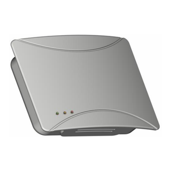
E4000NG air quality probe Installation manual
Ver
Date
V1
Initial
V9
Sep 2012
V10
Nov 2012
V11
Dec. 2012
V12
May 2013
V13
Oct 2013
V14
Oct 2015
V15
Oct 2018
www.nano-sense.com
Modification / Update
Version Initial/Initial version
Initial mass prod version
Air proof wiring
Temperature sensor position
LED option + High performance Positioning
Complementary KNX power supply
HS LS for analogue option
Change from E4000 to E4000-NG (new EEP, new CO2 and RH sensor)
setting of RH threshold and type of VOC measurement
All Rights Reserved
Tel: 33 (0)1 41 41 00 02
page 1/27
Advertisement
Table of Contents

Related Manuals for NanoSense E4000NG


Summary of Contents for NanoSense E4000NG
- Page 1 E4000NG air quality probe Installation manual Date Modification / Update Initial Version Initial/Initial version Sep 2012 Initial mass prod version Nov 2012 Air proof wiring Dec. 2012 Temperature sensor position May 2013 LED option + High performance Positioning Oct 2013...
-
Page 2: Table Of Contents
Guide d’Installation sonde E4000 E4000 probe Installation Guide Summary Security Positioning Installation Wiring Motherboard preparation 5.1. RS485 5.2. Optional Bus board 5.2.1. Install the daughter board 5.2.2. Mount the BUS connector 5.3. Analog Option 5.4. LED Option 5.5. EnOcean Option 5.6. -
Page 3: Security
Guide d’Installation sonde E4000 E4000 probe Installation Guide 1. Security WARNING Danger of death, risk of electric shock and fire! The installation should only be undertaken by a qualified electrician! To apply for correct bus and power cables and to activate the device, comply with the state of the art and standards. -
Page 4: Installation
Guide d’Installation sonde E4000 E4000 probe Installation Guide 3. Installation Attach to the wall through two holes in the case. Take care of case orientation (TOP –BOTTOM) ONLY use screws with bent heads Maximum height of the head 2 mm. BOTTOM Make sure to position the hole of cables path at the case bottom... -
Page 5: Optional Bus Board
Guide d’Installation sonde E4000 E4000 probe Installation Guide Optional Bus board 5.2. Install the daughter board 5.2.1. KNX board LON board Insert the Bus board into the motherboard of the probe. Check that there is no shift in the connectors. Mount the BUS connector 5.2.2. -
Page 6: Enocean Option
Guide d’Installation sonde E4000 E4000 probe Installation Guide EnOcean Option 5.5. module Antenna EnOcean radio For good receiver performance, great care must be taken about the space immediately surrounding the antenna since this has a strong influence on screening and detuning the antenna. The antenna should be drawn out as far as possible and must never be cut off. -
Page 7: Temperature Sensor
Guide d’Installation sonde E4000 E4000 probe Installation Guide Temperature sensor 6.1. Standard positioning 6.1.1. The temperature sensor is located on the lowest part of the board. This sensor is located at the end of a coiled pigtail 3cm long conductor to minimize thermal bridging with the board and thus reduce the thermal inertia. - Page 8 Guide d’Installation sonde E4000 E4000 probe Installation Guide In RS485 version add 13mA for communication to the calculated consumption. Probes are queried one after the other. www.nano-sense.com All Rights Reserved Tel: 33 (0)1 41 41 00 02 page 8/27...
-
Page 9: Power Supply Connection
Guide d’Installation sonde E4000 E4000 probe Installation Guide In KNX version, the bus powers only the interface board, the main board is powered by the secondary 31V–DC power supply (yellow and white). Use a certified KNX power supply. Most of KNX power supplies have a secondary 31V-DC power supply (yellow and white cables and connector of the same colors). -
Page 10: Connecting To Ventilation And Other Elements
Guide d’Installation sonde E4000 E4000 probe Installation Guide Note: KNX or LON EnOcean Gateway Connecting the EnOcean module enables the gateway function between KNX or LON and EnOcean. In addition to the gateway function, this module is used to enrich the functions between the EnOcean sensors and EnOcean actuators by KNX or LON settings. -
Page 11: Enocean Sensor Mode Option
Guide d’Installation sonde E4000 E4000 probe Installation Guide EnOcean sensor mode option 7.2.4. Principle The link with the HVAC is done by radio waves. Pairing 7.2.4.1. In order to send the measured values or commands to actuators, it is necessary that the probe to be paired with one or more actuators. -
Page 12: Transmission Range
Guide d’Installation sonde E4000 E4000 probe Installation Guide • Or Control valve wired (Bi Directional) (EEP 4BS: A5-20-03) • Or Control Generic HVAC Interface (Bi Directional) (EEP 4BS: A5-20-10) • Or Temperature (setting + measure) (EEP 4BS: A5-10-03) And for temperature cooling control: •... - Page 13 Guide d’Installation sonde E4000 E4000 probe Installation Guide Brick walls/ Plaster board/ Reinforced concrete Aerated concrete blocks Wood (dry) 10 meters through (ACB) 30 meters through maximum 20 meters through max. 5 walls 1 wall/ceiling maximum 3 walls Other materials Typical range Air (Visual contacts) 30m in passages, corridors, up to 100m in halls...
-
Page 14: Insert Gas Sensors
Guide d’Installation sonde E4000 E4000 probe Installation Guide 8. Insert gas sensors Sensor on mini SD card 8.1. VOC sensor module is supplied in sealed waterproof bags .Introduce them into the slot located on the back side of the card. Well comply with locations. -
Page 15: Powering
Guide d’Installation sonde E4000 E4000 probe Installation Guide 9. Powering At power up, the red status LED will flash alternatively with the green LED during the initial phase of gas sensors conditioning (30 seconds), and finally the green LED will flash every 2 seconds indicating the good functioning of the probe. -
Page 16: Threshold Settings (Enocean, Modbus Rs485 And Analogical Board)
Guide d’Installation sonde E4000 E4000 probe Installation Guide 10. Threshold settings (EnOcean, Modbus RS485 and Analogical Board) Position the micro switches 10.1. Two dry contacts of analog board (speed 1 and 2) or RS485 & EnOcean commands operate based on CO2, VOCs and RH parameterized thresholds by micro switches: Dry contact # 1 thresholds: CO2: 700 ppm or 1200 (selectable H = High / L = Low) during more than 10... -
Page 17: Rh (Humidity) Threshold Settings With Lcd Tool
Guide d’Installation sonde E4000 E4000 probe Installation Guide RH (humidity) threshold settings with LCD tool 10.2. It is possible to set the humidity threshold as follows: The adjustable threshold corresponds to the dry contact # 1 threshold of the previous chapter. Dry contact # 2 threshold is deduced from this threshold by adding 5% RH. -
Page 18: Co2 Baselines Expressed In Ppm
Guide d’Installation sonde E4000 E4000 probe Installation Guide CO2 Baselines expressed in ppm 10.3. 200 000 Lethal (deadly) for humans 100 000 Lethal in 10 minutes without an action for resuscitation 40 000 Threshold of irreversible effects on health 5000 Maximum concentration on workplace (8h) 4000 Bedroom poorly ventilated... -
Page 19: Type Of Voc Measure Settings
Guide d’Installation sonde E4000 E4000 probe Installation Guide Symptoms above 3000μg / m usually include drowsiness, eye and respiratory irritation, general malaise, headache, nausea and exacerbation of respiratory symptoms. Some data suggest that elevated levels of COVt amplify the harmful effects of specific harmful VOCs (cocktail effect). COVT Formaldehyde Benzene... -
Page 20: Connection Diagram According To Position Of Micro Switches
Guide d’Installation sonde E4000 E4000 probe Installation Guide V O C > To choose another mode press OK (Middle button) The display shows the possible modes: > Select the mode by moving the indicator with the right or left key then press OK (Middle button). Select "SAVE"... -
Page 21: Completion Of Installation
Guide d’Installation sonde E4000 E4000 probe Installation Guide 13. Completion of installation By clipping close the cover (the cover is symmetric and therefore can be mounted upside down) Apart from domestic installations, it is preferable to secure the cover using the two screws. The cover and housing have pre lateral holes. -
Page 22: Annexes
Guide d’Installation sonde E4000 E4000 probe Installation Guide ANNEXES 1. Installation of BUS connections 1.1 RS485 RS485 Modbus Connection - (A) + (B) Shielding of the cable * cable * : Never connect to the – of the power supply. RS485 Modbus connection is not optically isolated. -
Page 23: Programming The Physical Address
Guide d’Installation sonde E4000 E4000 probe Installation Guide 1.2 Programming the physical address In slave mode, it is possible to program directly the probe address by using buttons on the LCD tool. (up to address # 255). A default address is implemented and the probability that two sensors have the same address is 1 / 250 which prevent setting. -
Page 24: Choosing Cable Bus
Guide d’Installation sonde E4000 E4000 probe Installation Guide 2. Choosing Cable Bus RS485 2.1. The RS422 standard recommends 24AWG (0.23mm2) twisted pair cable with a capacity of 16 pF shunt per foot and 100 Ohms characteristic impedance. Although the standard does not specify anything for RS485 wiring, the cable can perfectly be used for RS485. -
Page 25: Ventilation Control
With regular change of sensor Use of CO sensors and specific Low Speed, High Speed management. NanoSense offers specific solutions for car parks. Note that a humidity outdoor sensor and/or a temperature outdoor sensor can be coupled with E4000- NG’s humidity and temperature sensors to optimize ventilation. -
Page 26: Specification
Guide d’Installation sonde E4000 E4000 probe Installation Guide 4. Specification Power supply from 15 to 33V DC and from 12 to 24V AC (preferably DC to minimize ageing) Consumption on KNX or LON bus: 9mA max (only for interface board) Consumption on 24V AC or 31V DC: 45 mA (+10 mA during RS485 communication) RS485 bus interface resident KNX bus interface module: Optional board (TP1 / E mode) -
Page 27: Drilling
Guide d’Installation sonde E4000 E4000 probe Installation Guide DRILLING This drawing is at scale one and can be use directly for drilling in removing this sheet. www.nano-sense.com All Rights Reserved Tel: 33 (0)1 41 41 00 02 page 27/27...
Need help?
Do you have a question about the E4000NG and is the answer not in the manual?
Questions and answers