Table of Contents
Advertisement
Quick Links
Advertisement
Table of Contents

Related Manuals for EPIC SAFETY Surf-km

Summary of Contents for EPIC SAFETY Surf-km
- Page 1 & surf-k LTE Alarm System Communicators Installation Guide...
-
Page 2: Table Of Contents
4.6. Terminal Connections ........................9 Other Hardware: ..........................10 RF expansion port is for future addition of more wireless capabilities to Surf-K and Surf-KM. . 10 • Antenna connector is for connecting our full frequency LTE antenna........10 •... -
Page 3: Overview
Aryo Cloud platform and iOS and Android smartphones. Surf-km and Surf-k use 3 zones to monitor legacy systems for generic burglary, fire, and panic alarms. Surf-km and Surf-k use zone 1 and... -
Page 4: In The Box
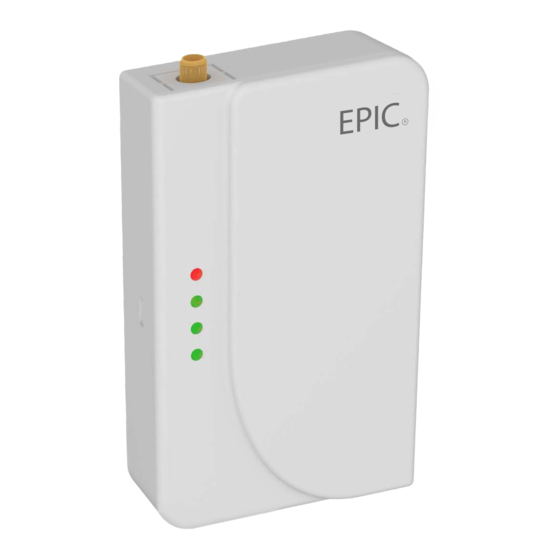
PGM 1 fort keyswitch arming and disarming. PGM 2 is used to trigger a supervisory zone on the panel for Surf-km and Surf-k troubles. 1.2. In the box • Surf-k or Surf-km • Quick installation guide • Antenna (75cm) 1.3. Identifying the Parts... -
Page 5: Introduction
2.2. Surf codes Surf-K and Surf-KM uses one master code (for main user) and 40 user codes to arm and disarm the host control panel when keyswitch arming is used or If Keybus connection is not used or available. These Codes are different from the host control panel Master and User Codes. -
Page 6: Pre-Installation Recommendations
• DO NOT install the antenna in a metal enclosure. 3.2. Cable length For suitable location to install Surf-K and Surf-KM, they can be installed up to 1000 feet away from the control panel. The distance would increase if you use higher guage wire. -
Page 7: Temperature
10 -14 -93 ~ -85 Acceptable 15 - 19 -83 ~ -75 Good 20 - 31 -73 ~ -51 Excellent 4.2. Temperature For correct operation, the unit must be in the operating range for temperature level. The different temperature levels and their corresponding interpretations are listed below. The temperature for the unit can be viewed on the cloud. -
Page 8: Led Indications
Led 1 On 10 ~ 12 Led 2 Blink 13 ~ 16 Led 2 On 17 ~ 19 Led 3 Blink 20 ~ 22 Led 3 On 23 ~ 25 Led 4 Blink 26 ~ 28 Led 4 On 29 ~ 31 Reboot If required based on Fast blinking... -
Page 9: Terminal Connections
Alternate Green progress blinking Update 4.6. Terminal Connections SURF-K / Surf-KM terminals description Terminal Name Connections Tip (T) Connection to panel phone TIP terminal for detection and capture of CID and SIA events to be sent to Aryo cloud and the monitoring center Ring ®... -
Page 10: Other Hardware
4.7. Connections description 4.7.1. Power SURF-K / Surf-KM could be powered by host control panel auxiliary 12-14 VDC power. External auxiliary power source with back up battery can be used if they use common ground. These devices can still operate with power range of 5 to 20 VDC. SURF-K / Surf- KM always monitor panel voltage and will generate power trouble when voltage drops below 9VDC. -
Page 11: Tip/Ring
4.7.4. Zones SURF-K / Surf-KM provide 4 zone inputs. Zone 1 is used for arm status in keyswitch arming and 3 zones are used to monitor generic alarm panels that do not use CID/SIA formats. Zones 2, 3 and 4 zones would be used for generic burglary, fire, and panic alarms as per section 1.4`s table. -
Page 12: Programming Recommendations
5.2. Programming recommendations 5.2.1. 1616/1832/1864 Section Description Turn options 4 on and options 7 and 8 off Enter any phone number Enter a system account number 311-318 If system has multiple partitions, enter an account number for each partition if any format other than SIA is used. 311 for partition 1, 312 for partition 2, and so on. -
Page 13: Pc 5020
partition 1, 352 is for partition 2, and so on. 367-374 Turn option 1 on for each partition open/close reporting. 367 is for partition 1, 368 is for partition 2, and so on. Turn option 1 on to enable communicator for digital monitoring. Options 3 and 4 must be off for DTMF dialing. -
Page 14: Pc 5010
Options 3 and 7 must be off for automatic SIA and CID reporting To enable keyswitch arming/disarming and make it work properly, program the following sections: Section Entry/Description Program a zone as type 22 for momentary keyswitch arm Program a PGM as 05 for system arm status 5.2.3. - Page 15 Turn options 4 on and options 7 and 8 off Enter any phone number Enter account number Enter 03 for CID reporting or 04 for SIA reporting Turn option 1 on for alarm/restore reporting. Turn option 1 on for open/close reporting. Turn option 1 on to enable communicator for digital monitoring.
-
Page 16: Interlogix Panels (Ge)
5.2 Interlogix Panels (GE) 5.2.1 GE Concord 5.2.1.1 Wiring Diagram 5.3 Paradox Panels 5.3.1 Espirit 728, 728 Express, 738, 738 Express 5.3.1.1 Wiring Diagram... -
Page 18: Paradox Sp6000, Sp 5500, Sp7000, Sp 4000
5.3.2 Paradox SP6000, SP 5500, SP7000, SP 4000 5.3.2.1 Wiring Diagram 5.4 Generic Panels 5.4.1 Wiring Diagram... -
Page 19: Trouble Conditions
If panel power fails below 9V, SURF-K/KM will trigger a trouble event on the host panel and send the signal to our cloud server and CMS. 6.2 Network Signal If radio signal falls below 9, Surf-K/Surf-KM will trigger a trouble event on the host panel and send the signal to our cloud server and CMS. -
Page 20: No Cellular Service
CMS. 6.5 SIM Card Error If there is a SIM Card Error, Surf-K/Surf-KM will trigger a trouble event on the host panel and send the signal to our cloud server and CMS. -
Page 21: Troubleshooting
Comm Test 7. Troubleshooting Trouble Indication Solution Primary Power Failure First LED fast blinking. Check the AC power of the alarm panel. Check if the battery of the alarm panel is operating normally. Network Signal 1. First LED blinking quickly. Move the antenna or SURF 2. -
Page 22: Specifications
SURF device is well connected 2. Check the settings of the alarm panel (CID or SIA). 8. Specifications HARDWARE Surf-K, Surf-KM Dimensions 115mm*37.5mm*14.75mm Weight 53.5g Operating temperature 32°F to 120°F (0°C to 48.9°C) Humidity... -
Page 23: Repair Under Warranty
Keybus (DSC) Tip/Ring Input Zone PGMs Status LEDs RF Expansion Port Trouble reporting Refer to section 6 above Antenna Length 75 cm Antenna frequency LTE Full band Communication Certification PTCRB, AT&T, FCC, IC 9. Repair under warranty All the warranty claims must be accompanied by a Return Merchandise Authorization (RMA) number which must be obtained before merchandise can be returned for any warranty replacement or repair. -
Page 24: Terms And Conditions
EPIC Safety You agree not to adapt, alter or create a derivative work from any of the material contained in this site or use it for any other purpose other than for your personal non-commercial use. -
Page 25: Product Warranty
EPIC Safety for all the purposes specified above; Indemnify EPIC Safety against all legal fees, damages and other expenses that may be incurred by EPIC Safety as a result of your breach of the above warrant; and Agree to waive any moral rights in your contribution for the purposes of its submission to and publication on the EPIC Safety site and the other purposes specified above. -
Page 26: Limitation Of Warranty
Epic. Custom products are only warranted to the extent that they do not function upon delivery. In such cases, Epic can repair, replace or credit as its option. This warranty is for the original owner only and is therefore non-transferable, non-assignable and is voided when the Warranted Product is transferred to another party.
Need help?
Do you have a question about the Surf-km and is the answer not in the manual?
Questions and answers