Table of Contents
Advertisement
Quick Links
Advertisement
Chapters
Table of Contents

Related Manuals for Becom CM-BF527

Summary of Contents for Becom CM-BF527
- Page 1 CM-BF527 Hardware User Manual Version 8...
- Page 2 Hardware User Manual - CM-BF527 Last change: 26. March 2019/Version 7 BECOM Systems GmbH Gutheil-Schoder-Gasse 17 1230 Wien AUSTRIA office.systems@becom-group.com http://systems.becom-group.com CM-BF527 – Hardware User Manual Template No.: 900-520 Rev A Publication date: February 4, 2020 Subject to change without notice. Errors excepted.
-
Page 3: Table Of Contents
Hardware User Manual - CM-BF527 Last change: 26. March 2019/Version 7 Table of Contents Introduction ...............................................6 Overview ..............................................6 Key Features ..........................................8 Applications ..........................................8 General Description ..........................................9 Functional Description ......................................9 Boot Mode ............................................9 Memory Map ..........................................10 2.3.1... - Page 4 Hardware User Manual - CM-BF527 Last change: 26. March 2019/Version 7 Side View ............................................25 Footprint ............................................25 Connectors ..........................................26 Support ............................................... 27 General Support ........................................27 Board Support Packages....................................27 Blackfin® Software Support ..................................27 7.3.1 BLACKSheep® OS ......................................27 7.3.2...
- Page 5 BECOM Systems takes no liability for any damages and errors causing of the usage of this board. The user of this board is responsible by himself for the functionality of his application. He is allowed to use the board only if he has the qualification.
-
Page 6: Introduction
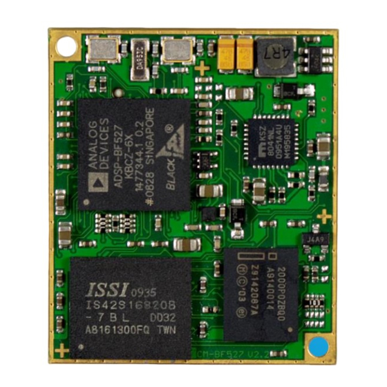
Last change: 26. March 2019/Version 7 Introduction The CM-BF527 is optimized on performance and functionality. The module integrates processor, RAM, flash, external peripheral controllers and power supply at a size of 31.5x36.5mm! It is based at the high performance ADSP-BF527 from Analog Devices. The Core-Module is designed for commercial usage (commercial temperature range). - Page 7 Hardware User Manual - CM-BF527 Last change: 26. March 2019/Version 7 8 MB of Byte-Addressable Flash • 32MByte SDRAM Version (see chapter 8.1) PF48F2000P0ZBQ0 (4Mx16, 64Mbit at 3.3V; addressable by 4 banks, 2MB each, ▪ controlled over GPIOs) Additional flash memory can be connected through the expansion board as parallel ▪...
-
Page 8: Key Features
Hardware User Manual - CM-BF527 Last change: 26. March 2019/Version 7 1.2 Key Features The CM-BF527 is a low-cost compact core module and measures only 36x31mm • Allows quick prototyping of product that comes very close to the final design •... -
Page 9: General Description
Figure 2-1 shows a detailed block diagram of the CM-BF527 module. Besides the SDRAM control pins and the pins used by the Ethernet physical transceiver (port H) the CM-BF527 has all other pins of the Blackfin processor on its two main 60 pin connectors. -
Page 10: Memory Map
Hardware User Manual - CM-BF527 Last change: 26. March 2019/Version 7 Switch Settings Boot Mode Description BM[3..0] 0000 0 (default) Idle - No boot Reserved 0001 Boot from 8- or 16-bit external flash memory 0010 Boot from 16-bit asynchronous FIFO. -
Page 11: Board Modifications
R26 to R24 for PG11 and R19 to R14 for PH9 from your Core Module. The flash address lines A20 and A21 are pulled low. Figure 2-2: default GPIO routing Warning BECOM Systems cannot take responsibility for customer-modified boards. If you need modifications, please request a quote at office.systems@becom-group.com. © BECOM Systems 2020 11 | 33... -
Page 12: Externally Addressable Memory (On Connector)
Hardware User Manual - CM-BF527 Last change: 26. March 2019/Version 7 Figure 2-3: Assembly drawing bottom view To access more than 8MB flash memory (64MB) you can add the 0 Ω resistor array R2. But be aware to not connect the IO pins PG10, PG9 and PG1. -
Page 13: Specifications
Hardware User Manual - CM-BF527 Last change: 26. March 2019/Version 7 3 Specifications 3.1 Electrical Specifications 3.1.1 Maximum Ratings Stressing the device above the rating listed in the absolute maximum ratings table may cause permanent damage to the device. These are stress ratings only. Operation of the device at these or any other conditions greater than those indicated in the operating sections of this specification is not implied. -
Page 14: Esd Sensitivity
Hardware User Manual - CM-BF527 Last change: 26. March 2019/Version 7 3.1.3 ESD Sensitivity ESD (electrostatic discharge) sensitive device. Charged devices and circuit boards can discharge without detection. Although this product features patented or proprietary protection circuitry, damage may occur on devices subjected to high energy ESD. -
Page 15: Connector Description
Hardware User Manual - CM-BF527 Last change: 26. March 2019/Version 7 4 Connector Description In the following tables you will find pin assignments for the Core Module connectors. Most pins are directly connected to the Blackfin processor. If not, please read the Notes below the table. -
Page 16: Table 4-1: Connector Description X1
Hardware User Manual - CM-BF527 Last change: 26. March 2019/Version 7 Pin No. Signal Name Type Function TRST I - 4k7 pull down JTAG JTAG I – 10k pull up JTAG JTAG Bmode2 I -10k pull down Boot mode Bmode3... -
Page 17: Connector X2
Hardware User Manual - CM-BF527 Last change: 26. March 2019/Version 7 For more information please see chapter 2.3. 4.2 Connector X2 Pin No. Signal Name Type Function Address bus Address bus Address bus Address bus Address bus Address bus Address bus... -
Page 18: Table 4-2: Connector Description X2
Hardware User Manual - CM-BF527 Last change: 26. March 2019/Version 7 Pin No. Signal Name Type Function Data Bus Data Bus RESET I/O see chapter 3.5 Reset Output enable Read enable AMS2 Memory select VDD-RTC Power USBD- USB_OTG_ID USB OTG... -
Page 19: Application Information
Hardware User Manual - CM-BF527 Last change: 26. March 2019/Version 7 5 Application Information 5.1 Supply Voltage Decoupling For a better stability we recommend to add a 100 nF and a 10 µF capacitor close to the 3V3 V supply pins. -
Page 20: Application Example Schematics
Hardware User Manual - CM-BF527 Last change: 26. March 2019/Version 7 5.3 Application Example Schematics 5.3.1 RJ45 schematic The KSZ8041 is connected via the RMII to the processor. The Rx and Tx pairs should be routed with 100 Ω differential lines. -
Page 21: Ethernet And Jtag
Hardware User Manual - CM-BF527 Last change: 26. March 2019/Version 7 5.3.2 Ethernet and JTAG VppOTP ADP3338 PH10/ND_CE/ERxD2/HOST_D10 5.0V 3.3V PH11/ND_WE/ETxD3/HOST_D11 PH12/ND_RE/ERxD3/HOST_D12 PH13/ND_BUSY/ERxCLK/HOST_D13 PH14/ND_CLE/ERxDV/HOST_D14 PH15/ND_ALE/COL/HOST_D15 PG0/HWAIT CLK_out PH9/SPISEL5/ETxD2/HOST_D9/TACLK3 PG9/TMR5/RSCLK0A/TACI5 PG10/TMR6/TSCLK0A/TACI6 PG11/TMR7/HOST_WR 3.3V USB_VBUS Vin 3V3 Vin 3V3 10uF CM-BF527 ABE0... -
Page 22: Stand-Alone Ethernet Based Mpeg Webcam
5.3.3 Stand-alone Ethernet based MPEG Webcam The CM-BF527 module can be used as a stand-alone module for a camera system requiring only power supply and the direct attachment of a compatible video camera. An extender board including a camera is available at BECOM Systems (EXT-BF5xx-CAM). -
Page 23: Table 5-3: Bill Of Materials Of A Stand-Alone Ethernet Based Mpeg Webcam
Hardware User Manual - CM-BF527 Last change: 26. March 2019/Version 7 Designator Value Type Description Quantity CM-BF537 green SMD LED DC-8 Power connector DC-8 RJLBC-060TC1 RJ45 with transformer R1, R3, R6 Resistor R2, R4, R5 220R Resistor S1, S2 Push button... -
Page 24: Mechanical Outline
The module is shipped with two 60-pin connectors. 6.2 Bottom View Figure 6-2 shows the TOP VIEW of the bottom placed connectors (through the Board View) of the CM-BF527 Core Module. All dimensions are given in millimeters! © BECOM Systems 2020... -
Page 25: Side View
Hardware User Manual - CM-BF527 Last change: 26. March 2019/Version 7 Figure 6-2: Mechanical outline and bottom connectors (top view The mechanical outline represents a TOP VIEW of the connectors placed at the bottom of the core board. 6.3 Side View 31.0... -
Page 26: Connectors
Hardware User Manual - CM-BF527 Last change: 26. March 2019/Version 7 Figure 6-4: Recommended footprint of the Core Module (top view) If there is no need to affix the Core Module, then you may omit the two M2 screwing holes. -
Page 27: Support
Analog Devices Blackfin® embedded processors. This high-performance OS is based on the reliable and stable real-time VDK kernel from Analog Devices that comes with VDSP++ IDE. Of course, BLACKSheep® OS is fully supported by all BECOM Systems Core- Modules and development hardware. -
Page 28: Ordering Information
100-1253-2 CM-BF527-C-C-Q50S32F8 (CM-BF527) Commercial 100-1254-2 CM-BF527-C-C-Q50S64F8 (CM-BF527-64SD) Commercial Table 8-1: Ordering information Note Custom Core Modules are available on request! Please contact BECOM Systems (office.systems@becom-group.com) if you are interested in custom Core Modules. © BECOM Systems 2020 28 | 33... -
Page 29: Dependability
30°C of all Core Module components except the Blackfin® processor (80°C) and the memories (70°C). We use the MTBF Calculator from ALD (http://www.aldservice.com/) and use the reliability prediction MIL-217F2 Part Stress standard. Please get in touch with BECOM Systems (office.systems@becom-group.com) if you are interested in the MTBF result. -
Page 30: Product History
Flash PF48F2000P0XBQ0 ETH-Physical KSZ8041 2.3.0 Processor ADSP-BF527KBCZ-6 (Rev 0.2) IS42S16160D-7BL (64MB) Flash IS29GL256-70DLEB (32MB) ETH-Physical KSZ8041 Table 10-1: Overview CM-BF527-C-C-Q50S32F8 (CM-BF527) product changes 10.1.2 CM-BF527-C-C-Q50S64F8 (CM-BF527-64SD) Version Component Type 2.2.1 Processor ADSP-BF527KBCZ-6 (Rev 0.2) IS42S16320B-7BL (64MB) Flash PF48F2000P0ZBQ0A (8MB) ETH-Physical KSZ8041 2.2.2... -
Page 31: Document Revision History
Updated product photo 2011 10 18 Table 3-2: Electrical characteristics update 2011 05 11 Added Figure 2-3 and updated design. 2010 06 28 Updated to new design from CM-BF527 V1.x HUM. Table 11-1: Revision history © BECOM Systems 2020 31 | 33... -
Page 32: List Of Abbreviations
Hardware User Manual - CM-BF527 Last change: 26. March 2019/Version 7 12 List of Abbreviations Abbreviation Description Analog Devices Inc. Analog Input Asynchronous Memory Select Analog Output Core Module Direct Current Digital Signal Processor Enhanced Core Module External Bus Interface... -
Page 33: A List Of Figures And Tables
Last change: 26. March 2019/Version 7 List of Figures and Tables Figures Figure 1-1: Main components of the CM-BF527 Core Module ............................6 Figure 2-1: Detailed block diagram........................................9 Figure 2-2: default GPIO routing ..........................................11 Figure 2-3: Assembly drawing bottom view ....................................12 Figure 5-1: Schematic of reset circuit on the Core Module ............................19...
Need help?
Do you have a question about the CM-BF527 and is the answer not in the manual?
Questions and answers