Sign In
Upload
Manuals
Brands
Becom Manuals
Control Unit
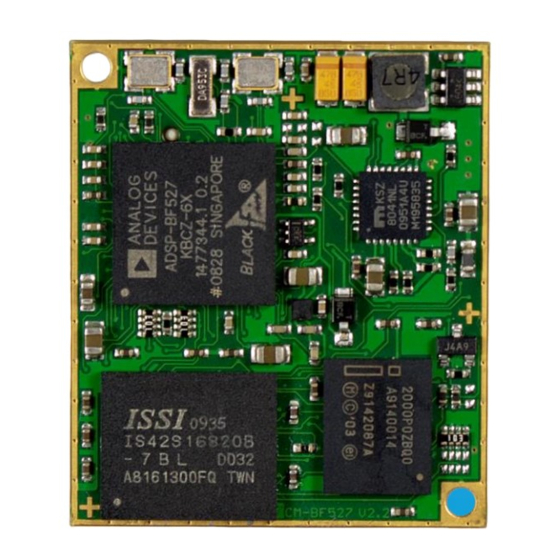
CM-BF527
User Manuals: Becom CM-BF527 Control Unit
Manuals and User Guides for Becom CM-BF527 Control Unit. We have
1
Becom CM-BF527 Control Unit manual available for free PDF download: Hardware User Manual
Becom CM-BF527 Hardware User Manual (33 pages)
Brand:
Becom
| Category:
Control Unit
| Size: 0 MB
Table of Contents
Table of Contents
3
Overview
6
Figure 1-1: Main Components of the CM-BF527 Core Module
6
Introduction
6
Key Features
8
Applications
8
General Description
9
Functional Description
9
Boot Mode
9
Figure 2-1: Detailed Block Diagram
9
Table 2-1: Boot Mode Description
10
Core Module Memory
10
Memory Map
10
Board Modifications
11
Figure 2-2: Default GPIO Routing
11
Table 2-2: Blackfin Memory Assignment
11
Externally Addressable Memory (on Connector)
12
Figure 2-3: Assembly Drawing Bottom View
12
Table 2-3: IO Pin to Flash Address Pin Assignment
12
Table 2-4: Externally Addressable Memory
12
Table 3-1: Absolute Maximum Ratings
13
Table 3-2: Electrical Characteristics
13
Specifications
13
Operating Conditions
13
Maximum Ratings
13
Electrical Specifications
13
ESD Sensitivity
14
Connector Description
15
Connector X1
15
Table 4-1: Connector Description X1
16
Connector X2
17
Table 4-2: Connector Description X2
18
Application Information
19
Supply Voltage Decoupling
19
Reset Circuit
19
Figure 5-1: Schematic of Reset Circuit on the Core Module
19
Application Example Schematics
20
RJ45 Schematic
20
Figure 5-2: Schematic for RJ45 Connection
20
Table 5-1: Bill of Material RJ45
20
Table 5-2: Bill of Material of ETH and JTAG
21
Figure 5-3: Configuration with Ethernet and JTAG Connector
21
Ethernet and JTAG
21
Stand-Alone Ethernet Based MPEG Webcam
22
Figure 5-4: Stand-Alone Ethernet Based MPEG Webcam
22
Table 5-3: Bill of Materials of a Stand-Alone Ethernet Based MPEG Webcam
23
Mechanical Outline
24
Top View
24
Bottom View
24
Figure 6-1: Mechanical Outline and Components on Top Side
24
Figure 6-3: Side View with Connector Mounted, 0.5Mm Tolerances
25
Footprint
25
Figure 6-2: Mechanical Outline and Bottom Connectors (Top View)
25
Side View
25
Connectors
26
Figure 6-4: Recommended Footprint of the Core Module (Top View)
26
Table 6-1: Core Module Connector Types
26
Table 6-2: Baseboard Connector Types
26
Upcoming Products and Software Releases
27
Blackfin Design Services
27
Uclinux
27
Labview
27
Blacksheep® os
27
Blackfin® Software Support
27
General Support
27
Support
27
Board Support Packages
27
Ordering Information
28
Table 8-1: Ordering Information
28
Dependability
29
Mtbf
29
Table 10-1: Overview CM-BF527-C-C-Q50S32F8 (CM-BF527) Product Changes
30
Table 10-3: Overview Product Anomalies
30
Table 10-2: Overview CM-BF527-C-C-Q50S64F8 (CM-BF527-64SD) Product Changes
30
CM-Bf527-C-C-Q50S32F8 (CM-Bf527)
30
Anomalies
30
CM-Bf527-C-C-Q50S64F8 (CM-Bf527-64Sd)
30
Version Information
30
Product History
30
Document Revision History
31
Table 11-1: Revision History
31
List of Abbreviations
32
Table 12-1: List of Abbreviations
32
A List of Figures and Tables
33
Advertisement
Advertisement
Related Products
Becom CM-BF537
Becom Bluetechnix Argos 3D P32X
Becom Categories
Accessories
3D camera
Computer Hardware
Control Unit
Digital Camera
More Becom Manuals
Login
Sign In
OR
Sign in with Facebook
Sign in with Google
Upload manual
Upload from disk
Upload from URL