
Related Manuals for Lncoon JM-C41


Summary of Contents for Lncoon JM-C41
-
Page 1: Jm-C41 Gps Tracker
JM-C41 GPS Tracker (4G Version) Email: support@lncoon.com Website: www.lncoon.com Tracking Platform: Lncoon... -
Page 2: Table Of Contents
Catalogue JM-C41 GPS Tracker ............................1 (4G Version) ................................1 Tracking Platform: Lncoon ..........................1 Part I - Product Introduction ..........................3 1.1 Product Schematic ............................ 3 (1) Power Status (Red) ..........................4 (2) GNNS Status (Blue) ..........................5 (3) Celluar Status (Green) ......................... 5 Part II - Specification &... -
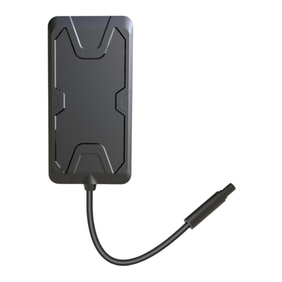
Page 3: Part I - Product Introduction
Part I - Product Introduction 1.1 Product Schematic Power Swtich Power Indicator GPS Indicator GSM Indicator SIM Slot Back Cover 1.2 Product Accessories Name Quantity Unit Remark Device piece Power Cable piece 1M length Relay User Manual piece... -
Page 4: Power Status (Red)
1.3 Interface Definition Anode ( 9-90V ) Black Negative Orange ACC Detection Oil&Power Cut Relay Yellow 1.4 LED Indication (1) Power Status (Red) Status Meaning On for 0.3s, Off for 0.3s Low Power On for 1s, Off for 0.3s Fully Charged On for 0.1s, Off for 0.3s Working Normally Charging (Higher priority than... -
Page 5: Gnns Status (Blue)
(2) GNNS Status (Blue) Status Meaning On for 0.3s, Off for 0.3s Searching GNSS Signal Solid On Positioned GNSS module is in sleep mode or not working (3) Celluar Status (Green) Status Meaning On for 0.3s, Off for 0.3s Network Initializing On for 1s, Off for 0.3s Receiving signal normally On for 0.1s, Off for 0.3s... -
Page 6: Part Ii - Specification & Features
Part II - Specification & Features 2.1 Product Specification Item Specifications Network 4G & 2G FDD: B1/B3/B5/B7/B8/B20 Frequency TDD: B34/B38/B39/B40/B41 GSM: 900/1800MHz Accuracy < 10 meters CEP Relay Optional Avg.hot start ≤1sec TTFF(open sky) Avg.cold start ≤32sec Indicator GPS(Blue), Cellular(Green),Power(Red) Battery 60mAh, 3.7V Li-Polymer Battery Voltage... - Page 7 2.2 Product Features Normally the operation path is List -> Device -> Command Functions Operation Path Power Cut Off Alarm Setting By 4 Ways 1. Platform 2. Plaform+SMS 3. Platform+Call 4. Platform+SMS+Call Overspeed Alarm Setting By 2 Ways 1. Platform 2.
- Page 8 Vibration Alarm Setting By: Upload Way / Vibration Numbers / Detection Time / Delay to enable alarm / Alarm Vibration Vibration Sensitivity Ranges:1-5 The smaller value the more sensitive...
- Page 9 Remote Control Fuel & Power cut off or restore Calling Setting Allow 3 numbers to receive help information...
- Page 10 On/Off Alarm Setting Driving Behavior Alarm Sharp accelerate/decelerat e alarm, Sharp Turn alarm, collide alarm, rollover alarm...
-
Page 11: Part Iii - Product Installation
Part III - Product Installation 3.1 Device Installation (1) Check Device Confirm whether the appearance of the equipment is good and whether the relevant accessories are complete. 3.2 Install Sim Card (1) Prepare the Right Size of Sim Card Choose Micro SIM card with access to GPRS and SMS ... -
Page 12: Wiring Diagram
the device Back Cover Power Switch SIM Card Slot Note: the SIM card cannot be installed reversely and the GPRS service is activated,as well as the sufficient charges. 3.3 Wiring Diagram (1) Power Wiring: Use a multimeter to find the battery positive and negative por leads A. - Page 13 B. Find the constant power of the car in the fuse box, connect it to C41 Red Wire...
- Page 14 C. After correctly connect power and ground cable, the tracker device C41 will power on (2) ACC Wiring: Use a multimeter to find the ACC line, the judgment method A. When ACC is off, the voltage is 0.00V like below B.
- Page 15 C. After picking out the ACC fuse, then connect it to the C41 ACC orange wire...
- Page 16 (3) Relay Wiring: Petrol / Electricity Cut Off , relay is needed if you wish disconnect petrol supply A. First find the oil pump power wire and use the scissors to cut it off like below B. Then connect relay white wire(85) and green wire(87a) together to the pump power input end...
- Page 17 C. Next connect relay green wire (30) to the pump power output end D. Finally connect relay yellow wire(86) to the C41 yellow wire...
-
Page 18: Product Wiring Diagram
(4) Product wiring diagram... - Page 20 3.4 Electric Vehicle Installation Position Mounted on Headlights ( priority position ) Under the Pedal...
-
Page 21: Motorcycle Installation Position
3.5 Motorcycle Installation Position Inside the headlight cover, near the stopwatch Under the rear seat ( priority position ) Inside the Taillight cover Or the pastic components Note: the satellites signal will greatly degrade if be installed under the driver Inside Front Cover Under ( priority position ) -
Page 22: Part Iv - Device Setting
Rear Windshield Under the front Trim Panel Around Dashboard Note: The device should be installed face up to the sky. If the windshield is pasted with a metal thermal insulation layer or a heating layer, it will reduce the signal strength of the satellite, which may make it difficult to locate the satellite. -
Page 23: By Sms Command
No need any setting when power on the device,the APN setting will be automatically finshed (2) By SMS Command Please confirm the APN information with the mobile network operator, and send below SMS commands to the phone number of the SIM card (carried by the device) to configure APN parameters: APN,apnname# E.g. -
Page 24: Part V - Platform Operation
Please confirm the server information with your software service provider, and send below SMS commands to the phone number of the SIM card (carried by the device) to configure server parameters. SERVER,mode,domain name/IP address,port,0# E.g. SERVER,1,www.ydpat.com,8011,0# SERVER,0,211.154.135.113,8011,0# Mode=1, means set with domain name; Mode=0, means set with IP address. -
Page 25: Register & Login Into Platform
5.1 Register & Login Into Platform (1) Download App by scanning below QR code (2) Create an Account by email you oftenly used... - Page 26 (3) Login onto Account and Add Device into App *********** Input or scan device Imei no. which can be found onto the box or backside of device...
- Page 27 (4) Activate the Device by Top-up Platform Service It directly recognized the ICCID no. of sim card...
- Page 28 Finished the payment by paypal or credit/debit card, then the device will be activated...
-
Page 29: Part Vi - Troubleshooting
Part VI - Troubleshooting Problem Solution Check APN and server settings. Check whether the data service Unable to connect to of SIM card is enabled. tracking platform Check the balance of your SIM card. Check whether the external power is well connected. The device is offline on Check if the device is in an area the platform... - Page 30 Drifting may happen if in an area with poor GNSS signal such as Location Drifts urban canyon or basement. Check whether the device is firmly fixed. Make sure format command is correct. No reply from device Check if the device is in an area after send it a without network.
-
Page 31: Part Vii - Get The Help
Part VII - Get The Help If any problem CHAT ON APP CHAT WITH US Login onto “LNCOON” App to talk with us online directly CHAT BY WHATSAPP OR FB WhatsAPP : 0086-13423860204 CHAT WITH US Facebook : 0086-13423860204 EMAIL support@lncoon.com...
Need help?
Do you have a question about the JM-C41 and is the answer not in the manual?
Questions and answers