
Related Manuals for RS Automation OEMax CSD7

Summary of Contents for RS Automation OEMax CSD7
- Page 1 CSD7 Servo Drive (EtherCAT Network type) User Manual Catalog Number(s) : CSD7_**BN(F)1...
- Page 2 In no event will RS Automation Co., Ltd. be responsible or liable for indirect or consequential damages resulting from the use or application of this equipment.
- Page 3 Manual Revision History The revision history of the manual provides the brief description of each manual revision. CSD7-UM001A-EtherCAT-EN-Oct 2015 Revision Month, Year Manual Version Manual Version Revision Information Revision Date First edition October 2015 CSD7 Servo Drive (EtherCAT)
-
Page 5: Table Of Contents
Table of Contents ..............MPORTANT NFORMATION ............P-1 HOULD ANUAL ............... P-1 BOUT UBLICATION ................P-1 DDITIONAL ESOURCES ............ P-2 ONVENTIONS SED IN ANUAL Object Description Format ..............P-2 Number of Each Digit in 7-Segment for Setting Parameters P-4 Terminology ....................P-4 Notation Description ................ - Page 6 Name and function of each terminal ..........3-5 Main Power Connector (L1, L2, L3) and Control Power Connector (L1C, L2C) ................3-6 Motor Power Cable Connector (U, V, W) ........3-6 Regenerative Resistor Connector (B1, B2) ........3-6 Electric Circuit Diagram................3-7 Using Method of Socket and Lever ..........
- Page 7 Connection Diagram of Encoder Signal ........3-30 ..............3-31 ENERAL RTICLES IRING Precautions ....................3-31 Fuse selection for the Drive ..............3-32 Noise Protection ..................3-33 Wiring When Multiple Drives Are Used ........3-36 CHAPTER 4. OPERATOR, BASIC SETTING AND COMMISSIONING ..4-1 ..................
- Page 8 Bootstrap State ..................5-10 PDO (P ) ............... 5-11 ROCESS BJECT Set PDO Mapping ................... 5-11 Set Sync Manager PDO Assignment..........5-12 Default PDO Mapping ................5-13 User Defined PDO Mapping ............... 5-15 SDO (S ) ..............5-17 ERVICE BJECT Abort Code ....................
- Page 9 PDO M ................ 7-15 APPING BJECTS .......... 7-21 ANAGER OMMUNICATION BJECTS ..........7-25 ANUFACTURER PECIFICATION BJECTS Standard Group 0 ..................7-25 Standard Group 1 ..................7-36 Standard Group 2 ..................7-41 Standard Group 3 ..................7-46 Standard Group 4 ..................7-51 Standard Group 5 ..................
- Page 10 Gain Group Switching, </G-SEL> Function ......... 8-42 Gain Switching Function ............... 8-43 CHAPTER 9. APPLICATION ................9-1 .....................9-2 OTOR Overview ......................9-2 Servo Fault ....................9-2 Overtravel Input (<P-OT>, <N-OT>) ..........9-3 Dynamic Brake .................... 9-4 ................9-6 OTOR RAKE ONTROL ........
- Page 11 Absolute Encoder Reset (0x300A, run-10) ........9-39 Storage of 2nd-Group Gain (run-11) ..........9-40 Parameter Initialization (run-12) ............9-41 ..............9-42 ONITOR MODE FUNCTION Introduction to monitor mode ............9-42 Built-in Key Button Operation ............9-45 SAG F ..................9-46 UNCTION Introduction to SAG Function ............
- Page 12 viii ............... B-6 AFETY UNCTION ONNECTOR CSD7 Servo Drive (EtherCAT)
-
Page 13: Who Should Use This Manual
CSD7 servo drive with a Motion Card. If you do not have a basic understanding of the CSD7 servo drive, contact your local RS Automation sales representative before using this product, for information on available training courses. -
Page 14: Conventions Used In This Manual
Preface Read This Document Information on the installation of your CSD7 CSD7 Servo Drive servo drive Installation Instructions Information on the installation and operation of Servo Motor User motors used together with CSD7 servo drive Manual Conventions Used in This Manual The conventions starting below are used throughout this manual. - Page 15 Preface numbers of 4 digits. e.g.) 0x1000, 0x2004, 0x6200, etc. Sub-Index : If there are sub-indexes, they are displayed as 2 digits in [ ] at the end of the indexes. e.g.) 0x1600[07], 0x1A00[09], 0x2005[04], etc. Object Name : Indicates the name of object Mode of Operation : Displays control modes that can be used.
-
Page 16: Number Of Each Digit In 7-Segment For Setting Parameters
Preface Number of Each Digit in 7-Segment for Setting Parameters The number of each digit in the 7-segment indicator at the front of CSD7 is defined as follows: These definitions apply throughout this user manual. Parameter & Each digit Definition [Ft-0.02][D0] [Ft-0.02][D1] [Ft-3.00][D2]... -
Page 17: Notation Description
Preface Notation Description Within the sentences of this manual, the following is expressed as shown below. Be fully aware of them when using the servo drive. 1. Use ‘/’ in front of Active Low signal. 2. A figure box with both the top corners cut off diagonally represents a circuit diagram. - Page 18 Preface 4. The following shows the symbols used on the circuit diagram. Symbol Description ▶ The figure represents the pin number of the connector, which can be marked with alphabets rather than the numbers. ▶ The Contact Point is the connection between the side Contact Point A and B with the connector.
-
Page 19: Manual Description Order
Preface Manual Description Order This manual is described in the view of users from the purchase to operation. 1. Describes things to know before using the product. 2. Describes the outline of product and marking. 3. Describes precautions upon product installation. 4. -
Page 20: Safety Precautions
Preface Safety Precautions This is CSD7 User Manual describes safety matters using the following marks. Safety marks deals with the important matters. If the following marks and contents of each mark are indicated in the contents of this user's manual, you must be fully aware of them and follow them. -
Page 21: Transportation
Preface Transportation Do not carry the product by holding the cable WARNING and the motor shaft. Installation and Wiring Install a cooling fan to prevent excessive WARNING temperature increase. (Refer to the Chapter 2) Be careful not to wiring cables around the heat sink. -
Page 22: Certificate
P-10 Preface Certificate CSD7 complies with all allicable local standards. Standards Servo Drive EMC Directive:201430/EU, KN EN61800_3, KC61800_3 EN61000_4_2, KN61000_4_2 EMC Directive EN61000_4_3, KN61000_4_3 EC Directive EN61000_4_4, KN61000_4_4 EN61000_4_5, KN61000_4_5 EN61000_4_6, KN61000_4_6 Low Voltage Directive EN61000_5_1 USA Standards NRTL UL508C Canada Standards NRTL/C C22.2No.14_10... - Page 23 Preface P-11 CSD7 Servo Drive (EtherCAT)
- Page 25 Chapter 1 Chapter 1. Before Using the CSD7 Servo Drive This chapter describes general matters optional specifications that you should know before using the CSD7 SERVO DRIVE............1-2 AME OF ERVO RIVE ........... 1-3 ODEL UMBER OF THE ERVO RIVE .............
-
Page 26: Chapter 1. Before Using The Csd7 Servo Drive
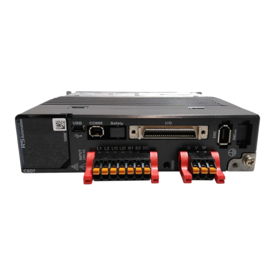
Before Using the CSD7 Servo Drive 1-2 Each Part Name of Servo Drive The following figure introduces the name of each part of the servo drive. Drive Name Plate Built-in Operator L1 L2 : Main Power Connector (400W & Under) USB : RSware Connector L1 L2 L3 : Main Power Connector (800W &... -
Page 27: Model Number Of The Servo Drive
• The drive type is RS Automation Servo Drive CSD7 Series. • The serial number is included on the nameplate. Be careful not to erase the serial number during the use. -
Page 28: Each Part Name Of Servo Motor
Before Using the CSD7 Servo Drive 1-4 Each Part Name of Servo Motor The following figure shows the each part name of servo motor. A motor without a brake does not have a motor brake cable. The name of each part may differ from the following figure according to the motor type. -
Page 29: Chapter 2. Installation
Chapter 2 Chapter 2. Installation This chapter describes matters to consider when installing the servo drive and the motor. Refer to the “ Exterior Dimension and Mouning Dimension ” on page A-4 for the dimension of the servo drive and the peripheral parts relevant to the installation. -
Page 30: Servo Drive Installation
Installation Servo Drive Installation Consideration Refer to the following figures when installing the servo drive. The most important thing to consider when installing the drive is the ambient temperature. Follow the operational temperature and the mounting space. Be sure to install the product vertically Install the Servo Drive Vertically The CSD7 series servo drive adopts a forced cooling method using the fan installed inside the product. - Page 31 Installation < RACK MOUNT > Apply M4 bolt to both top and bottom. Fixing Bolt For more detailed information about the drive dimension, • 400W & less : One M4 x L10 bolt for top and bottom please refer to the page A-4 “Exterior Dimension and •...
- Page 32 Installation When installing several drives, you must the following criteria. • Basically, keep 10 mm distance between products. • In case of zero stacking installation, attach an external fan to keep the ambient temperature of the products below 40 degrees Celsius.
- Page 33 Installation <100W, 200W> <400W> <800W, 1KW, 1.5KW> CSD7 Servo Drive (EtherCAT)
- Page 34 Installation Use the drive in a clean environment The installation environment for CSD7 Servo Drive is the pollution level 2 specified in the IEC-60664-1, and this product should be used at IP2x, so use the product in a clean environment without dust or humidity.
-
Page 35: Installation Environment
Installation Installation Environment The installation environment of the CSD7 servo drive is as follows. Table 2 The installation environment of the CSD7 Item Installation Conditions Storage -25 ~ 85 ℃ Temperature Operating 0 ~ 50 ℃ Temperature Operating 5 ~ 95 % RH at a place without condensations. Humidity 5-55Hz @ 0.35mm(0.014") double amplitude, continuous Vibration... - Page 36 Installation 1. Power cut-off device is required for maintenance and safety purposes. Local regulations should be observed. 2. When using the transformer, the voltage between each phase and neutral point/ground should not exceed the rated input. 3. Use of insulating transformer is optional. If used, the secondary ground in a transformer should be connected to the ground plate.
-
Page 37: Noise Filter And Ferrite Core
Installation Noise Filter and Ferrite Core Table 3 Noise Filter and Ferrite Core CSD7_ CSD7 drive 01BN1, 02BN1, 04BN1, 08BN1, 10BN1, 15BN1, 01BNF1 02BNF1 04BNF1 08BNF1 10BNF1 15BNF1 2090-XXLF-TC318(Tesch NF210/16) AC Power Filter 2090-XXLF-TC116(Tesch NF310/16) 2090-XXLF-TC116(008xx1, if single-phase is applied) Wire for AC power, Motor power, Encoder signal : OP14.2x28.5-6.8H Ferrite Core Wire for I/O, communication (USB &... - Page 39 Chapter 3 Chapter 3. Wiring This chapter describes the wiring information for motor, host controller and other peripheral devices connected to the servo drive, along with the circuit diagram................... 3-2 EFORE EGIN ..... 3-5 OWER UPPLY OTOR OWER EGENERATIVE ESISTOR I/O S (I/O) ...................
-
Page 40: Before You Begin
Wiring Before You Begin Pay attention to the following precautions when wiring. Wiring should be done only by the qualified CAUTION person. High voltage remains in the drive even through the power is off. Therefore, do not inspect components unless inside ‘Charge Lamp’... - Page 41 Wiring In this chapter, the circuit is divided into electric circuit and signal circuit for easier and more convenient explanation. Be fully aware of the names of each part when reading this user’s manual. Drive Name Plate Built-in Operator L1 L2 :Main Power Connector (400W &...
- Page 42 Wiring The input/output signal connector (I/O) and encoder signal connector (ENC) are explained in this chapter while the USB, EtherCAT and safety connectors are explained in the Appendix B, ‘Cable & Connector Specifications’. To use the Safe Torque Off (STO) feature available only in a premium model, external wiring using connectors as shown in the figure below is required;...
-
Page 43: Power Supply, Motor Power, Regenerative Resistor
Connect the condenser (+) polarity to the B1 terminal; Connector and (-) polarity to the DC- terminal. If it is necessary to connect an external condenser, be sure to contact RS Automation for advice. CSD7 Servo Drive (EtherCAT) -
Page 44: Main Power Connector (L1, L2, L3) And Control Power
Wiring Main Power Connector (L1, L2, L3) and Control Power Connector (L1C, L2C) As the main power input and control power input can be connected to the drive separately, a user can configure the peripheral circuit so that the drive itself can cut off only the main power selectively if there is an emergency. -
Page 45: Electric Circuit Diagram
Wiring Electric Circuit Diagram Control Panel Drive Fuse disconnector Servo Drive Fuse Circuit Breaker 1:1 Insulating Block Transformer 220V 3-phase AC Line AC Line Filter 50Hz/60Hz Regenerative Resistor Motor Ground Bar Expanation for each part 1. Power cut-off device is required for maintenance and safety purpose. - Page 46 Wiring 400 W and above (CSD7_04Bxx1 - CSD7_15Bxx1). For the product of 200 W and below (CSD7_01Bxx1, CSD7_02Bxx1), the B1 and B2 terminal should be kept with nothing connected. 6. For the high-frequency ground, a thick braided wire is connected among the product, equipment enclosure, machine frame and motor.
-
Page 47: Using Method Of Socket And Lever
Wiring Using Method of Socket and Lever This section describes how to use wiring socket and lever provided with servo drive. • Connect only one wire to the wire inlet of the socket. • If the wire is pulled accidentally with an excessive force, reconnect the wire after trimming it properly. - Page 48 Wiring 3-10 Insert the wire completely. If peeled core wire is CAUTION exposed, it may cause an electric shock. CSD7 Servo Drive (EtherCAT)
-
Page 49: I/O Signal (I/O)
Wiring 3-11 I/O Signal (I/O) I/O Connection Diagram This is the circuit diagram of a connector for I/O signal. It is divided into input on the left and output on the right. The Backup battery for absolute encoder does not have the separate terminal. - Page 50 Wiring 3-12 Table 7 I/O pin Specification Signal Symbol Description Signal Symbol Description Common for Digital input 1~4 COM_24V Encoder Signal Output A+ (Use DC 24V normally) Common for Touch probe input Encoder Signal Output A- TP_24V (Use DC 24V normally ) Touch_probe_1 Touch probe input 1 Encoder Signal Output B+...
-
Page 51: Sequence I/O Signal
Wiring 3-13 Sequence I/O Signal What is Sequence I/O Signal ? To provide the optimum performance that is suitable for user’s equipment, 20 pin connector of I/O is used to allow the drive can input/output signals that have various functions. Input provides 11 functions and you can freely allocate input signal of each function with 4 pins such as pin No. -
Page 52: Sequence Input Signal (Allocable)
Wiring 3-14 Sequence Input Signal (Allocable) The following is the brief explanation on 11 functions of sequence input signal. You can allocate each function to seqeunce input pin of I/O. Details for each signal are explained in the reference pages listed on the right side of the table. -
Page 53: Allocation Method For Sequence Input Signal
Wiring 3-15 Allocation Method for Sequence Input Signal Refer to the table below, and allocate the functions that you want to use to the 5 pin ~ 8 pin of the I/O. As shown in the Table 10 below, the function of all sequence inputs is fixed to the each digit of the related parameter. - Page 54 Wiring 3-16 0x200E Ft-0.14 Reserved Reserved Reserved Reserved </BANK-SEL> </R-ABS> 0x200F Ft-0.15 Reserved Reserved Initial Value: 0 Initial Value: 0 </HOM-SEN> 0x2010 Ft-0.16 Reserved Reserved Reserved Initial Value: 4 0x2011 Ft-0.17 Reserved Reserved Reserved Reserved 0x2012 Ft-0.18 Reserved Reserved Reserved Reserved 0x2013 Ft-0.19...
-
Page 55: Sequence Output Signal (Allocable)
Wiring 3-17 Sequence Output Signal (Allocable) The following is the brief explanation on 12 functions of sequence output signal. You can allocate each function to seqeunce output pin of I/O. Details for each signal are explained in the reference pages listed on the right side of the table. Table 12 I/O Sequence Output Signal Operation Output signal source... -
Page 56: Allocation Method For Sequence Output Signal
Wiring 3-18 Allocation Method for Sequence Output Signal Refer to the table below, and allocate the functions that you want to use to the pin No. (15,16), (17,18) and (19,20) of the I/O. As shown in the Table 14 below, the function of all sequence outputs is fixed to the each digit of the related parameter. - Page 57 Wiring 3-19 </RMS-CLT2> </RMS-CLT1> 0x201B Ft-0.27 Reserved Reserved Initial Value: 0 Initial Value: 0 The table below is the example to allocate sequence output signal. Table 15 Example for Sequence Output Configuration Allocation Example <Object Setting> The 0x2016[03] (or Ft-0.22[D2]) is the index for allocation 0x2016[03] = 3 of </BK>...
-
Page 58: Notice For Sequence Signal Allocation
Wiring 3-20 Notice for Sequence Signal Allocation When you allocate the different functions to the same pin of I/O as shown below, the drive indicates servo warning in the ‘Status Display Mode’. 0x200A[02] or Ft-0.10[D1] was set to ‘2’. It means that the INPUT#2 pin of I/O is used as <P-OT>... -
Page 59: General I/O Signal
Wiring 3-21 General I/O Signal General Input Signal (Fixed) External Power 24V Table 16 Power Input Symbol Operation Signal Name Function Details (Pin No.) Mode The common Input the external power of DC 24V as a control terminal for COM_24V (Pin power input for contact signal. -
Page 60: General Output Signal (Fixed)
Wiring 3-22 General Output Signal (Fixed) Encoder Signal Table 19 Encoder Signal Symbol Operation Signal Name Function Details (Pin No.) Mode Encoder signal A, B pulse in the form of line drive is EA+ (Pin #11) transmitted to external device through these pins. 9-24 page “Position EA- (Pin #12) -
Page 61: Emergency Stop Input
Wiring 3-23 Emergency Stop Input This drive has a built-in circuit for the emergency stop. To quickly respond to the equipment failure or dangerous situation, connect external emergency stop signal to #9 pin of I/O connector. The I/O output of host controller or external switch for emergency stop can be used as the emergency stop signal source of the drive. -
Page 62: Interfac With Output Circuit Of I/O
Wiring 3-24 Interfac with Output Circuit of I/O There are 2 types for the servo drive output circuits. Design the input circuit at the host controller suitable for the each output circuit. Line Drive Output Photo-coupler Output Line Drive Output Output signal (EA+, EA-, EB+, EB-) that converted the encoder serial data into 2 phase (A phase and B phase) pulse, are transmitted through line drive circuit. - Page 63 Wiring 3-25 In case of connection to the relay circuit of the host controller : DC 5~24V Relay Host controller In case of connection to the line receiver circuit of the host controller : DC 5~12V Line receiver * Host controller *...
-
Page 64: Specification Of Sto (Safe Torque Off)
Wiring 3-26 Specification of STO (Safe Torque Off) This drive adopts the STO function, which is technology used to prevent safety-related accident at the site and secure the safety of the user, facilities and production system. This section describes the STO function which reduces the maintenance time, and minimizes the downtime to increase productivity and save cost for greater enhancing the value added at the industrial site. -
Page 65: Timing Chart
Wiring 3-27 Timing Chart When a safe state is switched to an unsafe state as shown in the figure below, the time T1 taken until EDM signal is turned off is maximum 1 msec, and the time T2 taken until the torque is off is maximum 0.5 ms. - Page 66 Wiring 3-28 Connecting to Safety Sensor Safety Output Safety Sensor Servo Amp (Source) Control Output 1 SFI1+ Safety Input SFI1- Control Output 2 SFI2+ Safety Input SFI2- EDM+ EDM- EDM Input EDM Output Connecting Multiple Drives to a Single Safety Sensor Safety Output (Source) Safety Sensor Control Output 1...
-
Page 67: Encoder Wiring
Wiring 3-29 Encoder Wiring Encoder Signal Specification The following table describes the function for each pins of encoder connector (ENC). Table 24 Signal Specification of Encoder Connector (ENC) Pin No. of Servo Pin No. of Motor Encoder Function Remark Drive ENC Connector (CSMT,CSMR-17bit) Twisted pair VCC(5V) -
Page 68: Connection Diagram Of Encoder Signal
Wiring 3-30 CON B : Connector for connection to the encoder connector of servo motor Table 26 Connector for using encoder cable of servo motor Motor Type Housing Terminal Manufacturer Serial Abs.,, 170361-1 CSMT, CSMR 172161-1 Serial Inc. or 70365-1 Power cable connector for large capacity motor packed with the motor. -
Page 69: General Articles Wiring
Wiring 3-31 General Articles Wiring This part describes wiring to implement optimum performance of the servo drive in wiring and noise. Precautions Input Power Circut Use a thick wire as earth wire if possible. Class grounding recommended. (Recommendation: grounding resistance lower than 100 [Ω]) Only 1 point must be grounded. -
Page 70: Fuse Selection For The Drive
Wiring 3-32 If the noise is generated at command input cable, connect the cable GND to the SG(0V) befor the usage. Others Use the breaker or fuse for wiring to protect the servo drive. Make sure there is no continuous bending and stress to the wire. ... -
Page 71: Noise Protection
Wiring 3-33 Using a high-speed fuse is not possible. As the CAUTION power supply of the drive is condenser input type, if a high-speed fuse is used, it can blow even under normal circumstances. Noise Protection The high-speed switching device and microprocessor are used at the main circuit of the CSD7 servo drive. - Page 72 Wiring 3-34 3상 AC 170 ~ 253 Vrms, 50/60Hz LINE FILTER LINE FILTER Relay Sequence Generating Circuit Servo Motor 방열판 Ground Plate One Point Grounding Earth Grounding <Class 3 Grounding or Under> Extra caution is required when wiring the noise filter. The following figure describes precautions when wiring the noise filter.
- Page 73 Wiring 3-35 Separate the input and output wiring of the noise filter and do not tie up them together. 1st and 2nd Interference 1-2차 간섭 FILTER 1st 2nd FILTER 1st 2nd 1st and 2nd 1-2차 간섭 Interference FILTER FILTER 1st 2nd 1st 2nd Circuit Circuit...
-
Page 74: Wiring When Multiple Drives Are Used
Wiring 3-36 Earth wire of noise filter should be solely attached in the earth plate. Do not connect the earth wire of the noise filter to other earth wire together. FILTER FILTER 1st 2nd 1st 2nd If there is noise filter inside the case (panel), connect all of the earth wires and earth wires of other equipment inside of the case to the grounding plate. - Page 75 Wiring 3-37 1MCCB NOISE FILTER SW 2 ON SW 1 OFF Relay 1 Indicating Lamp for Servo-OFF Relay 1 알람 표시용 Lamp +24[v] Relay 1 /RDY+ /RDY- +24[v] +24[V] IN Note Note 0[v] E-STOP /RDY+ /RDY- +24[V] IN +24[v] Note Note E-STOP 0[v]...
-
Page 77: Chapter 4. Operator, Basic Setting And Commissioning
Chapter 4 Chapter 4. Operator, Basic Setting and Commissioning This chapter introduces the operator mounted on the servo drive. In addition, it describes the basic setting of servo drive, and also an example for simple startup................... 4-2 EFORE EGIN .................... -
Page 78: Before You Begin
Operator, Basic Setting and Commissioning Before You Begin About Servo-ON Signal This part describes Servo-ON signal for the control of the servo drive. About Servo-ON Signal Audio or TV can select and play music and display channel that the users want from the moment the power switch is on. However, the servo drive cannot run servo motor by simple applying the power. - Page 79 Operator, Basic Setting and Commissioning Servo-OFF and Servo-ON Table 28 Servo-OFF and Servo -ON 3. Apply the position, speed 1. Servo-OFFstate 2. Servo-ON state command etc. for the servo-on state and motor operation If the </ENABLE> signal is input ...
- Page 80 Operator, Basic Setting and Commissioning Servo-ON Signal Input Servo-On signals are entered through the network communication line from the host controller. With the ON state of the sequence input /ENABLE, the servo-ON signal should be entered through the EtherCAT network to turn Servo-ON. In case of auto Servo-On If the servo drive runs the motor without a command from the host controller as in the operation mode (run-00), (run-01), the drive...
-
Page 81: Operator
Operator, Basic Setting and Commissioning • All parameter setting after Chapter 4 should be Note done for the Servo-ON status and Servo-OFF status. • In this manual, ‘the servo drive status’ means whether the servo drive is in servo-ON status or servo-OFF status. -
Page 82: Icons For The Key Buttons
Operator, Basic Setting and Commissioning Icons for the Key Buttons Icon is used in description throughout the manual. Thus, be fully aware of the shape, name and function of icons. Table 29 Icon for the Key Buttons Indicator and Key Name Function Remark... -
Page 83: Structure Of The Entire Mode
Operator, Basic Setting and Commissioning Structure of the Entire Mode As shown in the figure below, the servo drive is divided into 5 types of control modes. The mode displayed after the power ON is the status display mode. Mode is changed whenever the MODE/SET key is pressed. Be fully aware of the following 5 types of modes and read the following. -
Page 84: Status Display Mode
Operator, Basic Setting and Commissioning Status Display Mode This section describes contents of the ‘Status Display Mode’. The figure below is an example of display for the description of the status mode. Refer to the table below for the meaning of each display. - Page 85 Operator, Basic Setting and Commissioning Table 31 Status Display and Description Displayed Message Description Set value of node address that is recorded in 0x2021 (Ft-0.33). In this case, the node address is set as 001. If the value is set to 000, the node address is given a set value by the host controller.
-
Page 86: Parameter Setting Mode
Operator, Basic Setting and Commissioning 4-10 Parameter Setting Mode This section includes brief explanation of the parameters in parameter setting mode. The Parameter sets and saves various functions to make drive suitable for equipment. There is a parameter that can be always set regardless of the status of the drive, and those that must be in certain status of the drive when setting them. -
Page 87: User-Defined Parameter Setting Mode
Operator, Basic Setting and Commissioning 4-11 User-Defined Parameter Setting Mode The user-defined parameter setting mode is a group of parameters which a user changes frequently. User-defined parameters are as follows. Even when the name of a parameter differs, if the number indication is the same, it is treated as the same parameter and saved as the same one. -
Page 88: Monitor Mode
Operator, Basic Setting and Commissioning 4-12 Monitor Mode This section includes brief explanation of the parameters in monitor mode. Displays several numerical data generated as the motor is controlled by the drive. The contents of the monitor mode can be checked regardless of the status of the drive. - Page 89 Operator, Basic Setting and Commissioning 4-13 The items like Position feedback, Potion Command, and Encoder Feedback Counter of the monitor mode Position feedback, whose value is more than 5 digits, is not displayed at once by the 5-digit 7-segment LED display. Therefore, it is displayed separately by left and right key.
-
Page 90: Basic Setting
Operator, Basic Setting and Commissioning 4-14 Basic Setting This section includes the introduction of the control mode and the basic setting. Overview of the Basic Setting Basic setting must be done before using the servo drive. Other parameters can be set after the basic setting. ... -
Page 91: Startup
Operator, Basic Setting and Commissioning 4-15 Startup Before Startup 1. Please be aware of wiring in Chapter 3 and connect main power and control power normally. In addition, by configuring emergency stop input circuit, clear the emergency stop status. 2. Connect the motor and encoder properly. 3. -
Page 92: Startup
Operator, Basic Setting and Commissioning 4-16 Startup Startup 1 : Start up the Drive by Using Jog Operation The jog operation is possible in Servo-OFF status. Remove the wiring between the drive and the host controller, or make EtherCAT communication state to ‘Init’. The speed of the motor can be set from the drive for the jog operation. - Page 93 Operator, Basic Setting and Commissioning 4-17 Startup 2 : Start Up the Drive by Changing the Speed Start up the drive by changing the speed from the initial value, 50 [rpm] to 1000 [rpm]. The change of Jog operation speed should be done at 0x2205 (Ft- 2.05).
- Page 95 Chapter 5 Chapter 5. EtherCAT Communication This chapter describes how to use EtherCAT communication for using EtherCAT network-type CSD7. CAT S .............. 5-2 THER LAVE NFORMATION ................. 5-2 DDRESS ................... 5-5 EFERENCE ODEL CAT ..........5-7 TRUCTURE OF OPEN OVER THER CAT S (ESM) ............
-
Page 96: Chapter 5. Ethercat Communication
EtherCAT Communication EtherCAT Slave Information The EtherCAT slave information (ESI) of the CSD7 is provided as an XML format file. The Master uses this information to perform network configuration, communication setting and control functions. Set Node Address Check and Set Node Address You can check and set node addresses in either of the following two ways. -
Page 97: Definition Of Node Address
EtherCAT Communication configure nodes with recognized node addresses. Definition of Node Address Node Address Description The node address is set by the master controller. 1~255 You can configure the node address in the Master using set values. Note) Changed set values are applied after power cycling. The factory-set value for node address is 0, in this case the node address is set by the master controller. - Page 98 EtherCAT Communication Table 39 LED state and EtherCAT communication state Name Color LED state EtherCAT communication state Initial state Blinking Pre-Operational state Green Single Flash Safe-Operational state Operational state No error state An invalid object command in the current state is received from Blinking the EtherCAT master Single Flash...
-
Page 99: Reference Model
EtherCAT Communication For more information about LED states, see "EtherCAT State Machine Note (ESM)". Reference Model The following Table 40 shows comparisons between OSI (Open Systems Interconnection) reference mode and EtherCAT communication model. When compared to the OSI reference model, the EtherCAT communication model don’t have 3 - 6 layers. Table 40 Comparisons between OSI reference model and EtherCAT model Layer OSI reference model... - Page 100 EtherCAT Communication Layer 2 (Data link layer) Controls access to the communication medium. Performs error detectin, (Point-to-point transfer on a link) Layer 3 (Network layer) Perform message routing Layer 4 (Transport layer) Provides transarent reliable data transfer (end-to-end transfer across a network which may include muliple links) Layer 5 (Session layer) Creates and manages dialogue among lower layers.
-
Page 101: Structure Of Canopen Over Ethercat
EtherCAT Communication Structure of CANopen over EtherCAT CSD7 drives use the drive profile of CiA402. The object dictionary on the application layer includes parameters, application data, process data and PDO mapping information between servo interface and driver application. PDO (Process Data Object) consists of object dictionaries that can be mapped on the PDO, while the contents of process data are defined by PDO mapping. -
Page 102: Ethercat State Machine(Esm)
EtherCAT Communication EtherCAT State Machine(ESM) The state machine of EtherCAT Slave is controlled by the EtherCAT master. EterCAT State Machine(ESM) includes a states defined by EtherCAT. Changes in ESM are requested by the Master. The Master can record the contents of EMS change requests to be changed in the Slave AL control register. - Page 103 EtherCAT Communication Table 42 Availability of ASCII Communication in ESM State ESM state Jog On (JOG0) Jog Off (SVROF) Auto Tuning (TAT01) EtherCAT communication cable open Init state Pre-Operational state Safe-Operational state Operational state ▶ The followings are the ASCII values and the meanings of the used control sign : Sing ASCII value Meaning...
-
Page 104: Bootstrap State
EtherCAT Communication 5-10 Bootstrap State This mode is used for downloading firmware. In the Bootstrap state, the servo drive can download firmware to the servo drive, using the FOE (File access over EtherCAT) protocol. When firmware downloading is completed, the Bootstrap state is shifted into the Init state in which there is no risk. -
Page 105: Pdo (Process Date Object)
EtherCAT Communication 5-11 PDO (Process Date Object) EtherCAT uses PDOs (Process Data Objects) to transmit data periodically. PDOs are divided into RxPDO that receives data from the master controller, and TxPDO that transmits data to the master controller. RxPDO Operation command or target value, etc Master Servo Controller... -
Page 106: Set Sync Manager Pdo Assignment
EtherCAT Communication 5-12 Set Sync Manager PDO Assignment Sync Manager Channel consists of several PDO. Sync Manager PDO Assign Object (RxPDO:0x1C12, TxPDO:0x1C13) describes how PDOs are related to the Sync Manager. The number of PDOs is written in Sub-index 0 of the Sync Manager PDO Assign table. In this table, Index 0x1C12 is for RxPDO and 0x1C13 for TxPDO. -
Page 107: Default Pdo Mapping
EtherCAT Communication 5-13 Default PDO Mapping The table below shows the PDO mapping that is set by default in CSD7. The default PDO is fixed and cannot be changed. This setting is defined in the EtherCAT slave information file (XML format file). •... - Page 108 EtherCAT Communication 5-14 Number of Size PDO Map PDO Map_Name Index Name Type sub index Entry (byte) 0x60F4 Following error actual value DINT 0x60B9 Touch Probe Status UINT 0x603F Error Code UINT 0x60FD Digital Inputs UDINT 0x6041 Status Word UINT 0x6064 Position Actual Value DINT...
- Page 109 EtherCAT Communication 5-15 User Defined PDO Mapping CSD7 supports PDOs that can be edited or added by the user. You can use up to 10 parameters per each PDO. RxPDO Mapping Table Number of Size PDO Map PDO Map_Name Index Name Type sub index Entry...
- Page 110 EtherCAT Communication 5-16 Number of Size PDO Map PDO Map_Name Index Name Type sub index Entry (byte) 10th User Definition 1st User Definition 2nd User Definition 3th txPDO Mapping TxPDO Max 10 (0x1B02) 10th User Definition 1st User Definition 2nd User Definition 4th txPDO Mapping TxPDO Max 10...
-
Page 111: Sdo (Service Date Object)
EtherCAT Communication 5-17 SDO (Service Date Object) The CSD7 servo drive supports SDO communication. SDO communication is used to set the object of CSD7 servo drive or to monitor its state. The host controller read data from related object in the object dictionary to monitor slave states, and write data to related object in the object dictionary to set the object. -
Page 112: Sync By Distributed Clock (Dc)
EtherCAT Communication 5-18 0x08000020 Data can not be read or written 0x08000021 Data can not be accessed because of local control 0x08000022 Data can not be read or written in the current state 0x08000023 Object is not in the object dictionary Sync by Distributed Clock (DC) EtherCAT communication uses distributed clock (DC) to synchronize between the Master and Slave. -
Page 113: Communication Timing
EtherCAT Communication 5-19 Communication Timing The EtherCAT sync processing runs separately in the Master and the Slave. Master Application Master Application Master Master user shift time Frame U Frame U Sync0 shift time Slave Cycle time (0x1C32[02]) Cycle time (0x1C32[02]) Shift time Cal+Copy time Shift time... -
Page 115: Chapter 6. Cia402 Drive Profile
Chapter 6 Chapter 6. CIA402 Drive Profile CSD7 Servo Drive was designed based on the CIA402 Drive Profile of EtherCAT. This Chapter describes the CIA402 drive profile to control CSD7 Servo Drive..................6-2 TATE ACHINE ................6-5 ODE OF PERATION ................. -
Page 116: State Machine
CIA402 Drive Profile State Machine The status of CSD7 Servo Drive is controlled by Control Word (0x6040). And each status of slave is written in Status Word (0x6041). State Machine EtherCAT CSD7 Servo Drive has states given in the boxes in the diagram below and the movement of each state is performed by the servo drive or master. -
Page 117: State Definition
CIA402 Drive Profile State Definition State Description Remarks Not ready to switch on Initialization is in progress with control power ON Automatically run by servo drive Initialization is completed Switch on disabled Automatically run by servo drive The servo drive parameters are available to set The main power is available to turn ON Ready to switch on The servo drive parameters are available to set... -
Page 118: Status Display
CIA402 Drive Profile * Bit 1 ; Enable voltage * Bit 0 ; Switch on ▶ Set to ‘0’ after Fault reset Status Display Each status is displayed as a combination of the following Statusword (0x6041) in the table below. Bits of the Statusword (0x6041) Status Bit 6... -
Page 119: Mode Of Operation
CIA402 Drive Profile Mode of Operation CSD7 supports the following mode of operation (0x6060) : • Cyclic Synchronous Position Mode • Cyclic Synchronous Torque Mode The operation modes of Servo Drive can be set in 0x6060 (Mode of Operation) and displayed in 0x6061 (Mode of Operation Display). - Page 120 CIA402 Drive Profile And the control functions of CSP mode are configured as follows : Fig. Control Functions of CSP Mode Target Position (0x607A) Limit Multiflier function Position actual value (0x6064) Position range limit (0x607B) Polarity (0x607E) Following error Software position limit (0x607D) Drive actual value control...
-
Page 121: Cyclic Synchronous Torque Mode (Cst Mode)
CIA402 Drive Profile Cyclic Synchronous Torque Mode (CST mode) In CST mode, the master transmits the target torque (0x6071) to servo drive every PDO cycles so that the servo drives carry out Torque control. In this mode, Position control and Velocity control are carried out in the master controller. - Page 122 CIA402 Drive Profile Related Object Index Sub-Index Name Data Type Access PDO Map Unit 0x6064 Position Actual Value DINT TxPDO pulse 0x6071 Target Torque RxPDO 0.1% 0x6076 Motor rated torque UDINT 0.1A 0x6077 Torque actual value TxPDO 0.1% 0x607E Polarity USINT 0x6080 Max motor speed...
-
Page 123: Torque Limit Function
CIA402 Drive Profile Torque Limit Function Target torque (0x6071) are subject to torque limits. Internal Torque Limit Value (value to be always applied) Target torque are limited by the following two indexes. 0x60E0 and 0x2407 are the positive torque limit values and the same function. 0x60E1 and 0x2408 are the negative torque limit values and the same function. -
Page 124: Related Object
CIA402 Drive Profile 6-10 </P-TL> and </N-TL> are sequence input signals. To use these functions, Note see 3-15 page " Allocation Method for Sequence Input Signal " to allocate signals. Use the </P-TL> signal for the external limit of positive torques and the </N-TL>... -
Page 125: Digital Input/Output
CIA402 Drive Profile 6-11 Digital Input/Output The following Indexes are used to display the states of digital input signals of CSD7 I/O or to control the output of digital out signals. Related Object Index Sub-Index Name Data Type Access PDO Map Unit 0x60FD Digital Inputs... -
Page 127: Chapter 7. Object Dictionary
Chapter 7 Chapter 7. Object Dictionary This Chapter describes object dictionary EtherCAT communication with CSD7. The CoE (CAN application protocol over EtherCAT) protocol is based on the object dictionary................ 7-2 BJECT ICTIONARY ....................7-2 의 D ............. 7-3 BJECT ESCRIPTION ORMAT ................. - Page 128 Object Dictionary Object Dictionary Area The CoE (CAN application protocol over EtherCAT) protocol is based on the object dictionary. All objects uses four-digit hexadecimal number and they are assigned in each areas as shown in the table below by each function. Index Area Description...
-
Page 129: Object의 Description Format
Object Dictionary Object의 Description Format Object Description Format The description format of objects are as follows : Object without Sub-Index Index Object Name Mode of Operation Setting Range Size(Data Type ) Unit Access PDO Map Attribute Init Value Ft-no <Set Range> <Size ( )>... - Page 130 Object Dictionary Possible (TxPDO) ; Transmission PDOs can be mapped No ; PDs cannot be mapped Attribute : Indicates the time during which changes are valid in the writing-enabled object. Always : Changeable at any time Servo off : Changes are valid when servo is OFF Power cycling : Changes are valid after the control power is reset ㅡ...
-
Page 131: Object Dictionary List
Object Dictionary Object Dictionary List The following table is the all objects list that are used in CSD7 servo drive. Object Index Index_Name Sub-Index Access Type 0x1000 Device Type UDINT 0x1001 Error Register USINT 0x1008 Device Name STRING(20) 0x1009 Hardware Version STRING(20) 0x100A Software Version... - Page 132 Object Dictionary Object Index Index_Name Sub-Index Access Type 0x2100 Velocity Response Level USINT 0x2101 System Gain UINT 0x2102 1st Velocity Loop P Gain UINT 0x2103 1st Velocity Loop I Gain UINT 0x2104 P/PI Control Switching Mode DT2104 0x2105 Threshold for P/PI Control Switching UINT 0x2106 Velocity Loop D Gain...
- Page 133 Object Dictionary Object Index Index_Name Sub-Index Access Type 0x230F 1st Damping Ratio UINT 0x2310 2nd Damping Frequency UINT 0x2311 2nd Damping Ratio UINT 0x2312 In-Position Range UINT 0x2313 Near-Position Range UINT 0x2314 Range of Available Following Error UDINT 0x2402 LPF Bandwidth of 1st Current Command UINT 0x2403 LPF Bandwidth of 2nd Current Command...
- Page 134 Object Dictionary Object Index Index_Name Sub-Index Access Type 0x2A0A Accumulated load factor of regenerative resistor DINT 0x2A0C The number of rotation of absolute encoder DINT 0x2A10 U Phase Current DINT 0x2A11 V Phase Current DINT 0x2A12 W Phase Current DINT 0x2A13 Motor Utilization DINT...
- Page 135 Object Dictionary Object Index Index_Name Sub-Index Access Type 0x606D Velocity Window UINT 0x6071 Target Torque 0x6072 Maximum Torque UINT 0x6074 Torque Demand Value 0x6076 Motor Rated Torque UDINT 0x6077 Torque Actual Value 0x6079 DC Link Circuit Voltage UDINT 0x607A Target Position DINT 0x607B Position Range Limit...
-
Page 136: General Objects
Object Dictionary 7-10 General Objects 0x1000 Device Type Setting Range Size (Data Type) Unit Access PDO Map Attribute Init Value Ft-no 4 byte(UDINT) 0x00020192 ▶ Indicate the numbers of device profiles in CoE. ▶ Definition of Set Value Name Description 0~15 Device Profile No. - Page 137 Object Dictionary 7-11 AC 170~253 Vrms 3P/1P, 6.25/10.82Arms, 800W, Network, w/o Aux CSD7_08BN1 0x02010004 feedback AC 170~253 Vrms 3P, 7.50Arms, 1000W, Network, w/o Aux feedback CSD7_10BN1 0x02010005 AC 170~253 Vrms 3P, 12.37Arms, 1500W, Network, w/o Aux feedback CSD7_15BN1 0x02010006 AC 170~253 Vrms 1P, 2.38Arms, 100W, Network, Aux feedback & Analog CSD7_01BNF1 0x02010011 output...
- Page 138 Object Dictionary 7-12 Sub-Index 3 Store CiA402 Parameters - Reserved Setting Range Size (Data Type) Unit Access PDO Map Attribute Init Value Ft-no 4 byte(UDINT) Sub-Index 4 Store CSD7 Specific Parameters Setting Range Size (Data Type) Unit Access PDO Map Attribute Init Value Ft-no...
- Page 139 Object Dictionary 7-13 Sub-Index 1 Restore All Default Parameters Setting Range Size (Data Type) Unit Access PDO Map Attribute Init Value Ft-no 4 byte(UDINT) Sub-Index 2 Restore Communication Default Parameters Setting Range Size (Data Type) Unit Access PDO Map Attribute Init Value Ft-no 4 byte(UDINT)
- Page 140 Object Dictionary 7-14 4 byte(UDINT) Sub-Index 4 Serial Number Setting Range Size (Data Type) Unit Access PDO Map Attribute Init Value Ft-no 4 byte(UDINT) ▶ This object indicates the device information. ▶ Sub-index 1 indicates the vendor ID. 0x1018[01] : Vendor ID = 0x0000033D, RSAutomation ▶...
- Page 141 Object Dictionary 7-15 PDO Mapping Objects Thes PDO (Process Data Objects) are used for the real-time data transmission through the CoE (CANopen over EtherCAT) protocol, in which the application objects are mapped. Use 0x1600 ~ 0x1604 for RxPDO mapping and 0x1A00 - 0x1A04 for TxPDO mapping. Sub- indexes 1 or higher indicate the information of mapped application objects.
- Page 142 Object Dictionary 7-16 2 byte(UINT) Sub-Index 7 디지탈 출력 (Digital Outputs : 0x60FE) Setting Range Size (Data Type) Unit Access PDO Map Attribute Init Value Ft-no 4 byte(UDINT) ▶ The first recieption PDO (0x1600) assignment 0x1601 Receive PDO Mapping Parameter 2 Sub-Index 0 Number of objects in this PDO Setting Range...
- Page 143 Object Dictionary 7-17 2 byte(UINT) Sub-Index 1 Control word : 0x6040 Setting Range Size (Data Type) Unit Access PDO Map Attribute Init Value Ft-no 2 byte(UINT) Sub-Index 2 Target Torque : 0x6071 Setting Range Size (Data Type) Unit Access PDO Map Attribute Init Value Ft-no...
- Page 144 Object Dictionary 7-18 Setting Range Size (Data Type) Unit Access PDO Map Attribute Init Value Ft-no 2 byte(INT) Sub-Index 5 Modes of operation Display : 0x6061 Setting Range Size (Data Type) Unit Access PDO Map Attribute Init Value Ft-no 1 byte(USINT) Sub-Index 6 Following error actual value : 0x60F4 Setting Range...
- Page 145 Object Dictionary 7-19 Setting Range Size (Data Type) Unit Access PDO Map Attribute Init Value Ft-no 2 byte(UINT) Sub-Index 8 Digital Inputs : 0x60FD Setting Range Size (Data Type) Unit Access PDO Map Attribute Init Value Ft-no 4 byte(UDINT) ▶ The second transmission PDO (0x1A01) assignment 0x1A02 Transmit PDO Mapping Parameter 3 Sub-Index 0...
- Page 146 Object Dictionary 7-20 ▶ The fourth transmission PDO (0x1A03) assignment 0x1A04 Transmit PDO Mapping Parameter 5 Sub-Index 0 Number of objects in this PDO Setting Range Size (Data Type) Unit Access PDO Map Attribute Init Value Ft-no 2 byte(UINT) Sub-Index 1 Status word : 0x6041 Setting Range Size (Data Type)
-
Page 147: Syncmanager Communication Objects
Object Dictionary 7-21 SyncManager Communication Objects The method of the memory for EtherCAT communication set with the objects from 0x1C00 to 0x1C33. 0x1C00 Sync Manager Communication Type Sub-Index 0 Number of used Sync Manager channels Setting Range Size (Data Type) Unit Access PDO Map... - Page 148 Object Dictionary 7-22 0x1C13 TxPDO assignment Sub-Index 0 Number of assigned TxPDOs Setting Range Size (Data Type) Unit Access PDO Map Attribute Init Value Ft-no 2 byte(UINT) Sub-Index 1 Assigned TxPDO 1 Setting Range Size (Data Type) Unit Access PDO Map Attribute Init Value Ft-no...
- Page 149 Object Dictionary 7-23 Setting Range Size (Data Type) Unit Access PDO Map Attribute Init Value Ft-no 2 byte(UINT) Sub-Index 12 Cycle Time Too Small - Reserved Setting Range Size (Data Type) Unit Access PDO Map Attribute Init Value Ft-no 2 byte(UINT) Sub-Index 31 Sync error - Reserved Setting Range...
- Page 150 Object Dictionary 7-24 Sub-Index 8 Get Cycle Time Setting Range Size (Data Type) Unit Access PDO Map Attribute Init Value Ft-no 2 byte(UINT) Sub-Index 9 Delay Time Setting Range Size (Data Type) Unit Access PDO Map Attribute Init Value Ft-no 4 byte(UDINT) Sub-Index 10 Sync0 순환...
-
Page 151: Manufacturer Specification Objects
Object Dictionary 7-25 Manufacturer Specification Objects These objects are a manufacturer-specific area and interlocked with the parameters that are used for the CSD7 functions. You can also check and edit Ft-*.** parameters in the table below, using the built-in operator at the front of CSD7 servo drives. The Parameter Group is divided into 6 groups as follows : Parameter Group Description of Parameter Group... - Page 152 Object Dictionary 7-26 1 byte(USINT) Servo Off Ft-0.02[D3] Sub-Index 1 Selection of DB Stop Method Ft-0.02[D0] RSWare : Drive - Stopping Functions - Fault and Disable Braking Value Description Name in RSWare Keep DB after DB stop Brake and hold Range DB is released after DB stop.
- Page 153 Object Dictionary 7-27 1 byte(USINT) Servo Off Ft-0.03[D0] Sub-Index 2 Reserved Sub-Index 3 Auto Tuning Speed Setting Range Size (Data Type) Unit Access PDO Map Attribute Init Value Ft-no 1 byte(USINT) *100rpm Servo Off Ft-0.03[D2] Sub-Index 1 Off-line Tuning Mode Setting Ft-0.03[D0] RSWare : Drive - Tuning - Autotuning - Off-Line Auto Tuning Mode Value...
- Page 154 Object Dictionary 7-28 1 byte(USINT) Power cycling Ft-0.05[D3] Sub-Index 1 Encoder Backup Battery Ft-0.05[D0] RSWare : Drive - Encoder - Encoder Backup Battery Value Description Name in RSWare Range Backup Battery Installed Installed Backup Battery Not Installed Not Installed Sub-Index 3 Gain Change Enable Ft-0.05[D2] RSWare : Drive - Tuning - Gain Switching - Gain Change Enable...
- Page 155 Object Dictionary 7-29 larger than the setups (level of gain control switching and hysteresis of control switching). 2nd gain selection when the positional deviation is larger than the setups (level of gain control Position Error switching and hysteresis of control switching). 2nd gain selection when more than one command Position Command pulse exists between 200usec.
- Page 156 Object Dictionary 7-30 Setting Range Size (Data Type) Unit Access PDO Map Attribute Init Value Ft-no 0x0~0xa 1 byte(USINT) Servo Off Ft-0.10[D3] ▶ Setting Range : 0x0 ~ 0xb : Always Off : Always On 1-A : Digital Input 1st Assignment for Sequence Input Signal Ft-0.10 RSWare : Drive - Digital Inputs Digit...
- Page 157 Object Dictionary 7-31 Sub-Index 2 Current Limit – Negative Current Limit (/N-TL) Ft-0.11[D1] Negative (/N-TL) Sub-Index 3 Current Limit – Positive Positive Current Limit (/P-TL) Ft-0.11[D2] (/P-TL) 0x200D 4th Assignment for Sequence Input Signal Sub-Index 0 Number of Entries Setting Range Size (Data Type) Unit Access...
- Page 158 Object Dictionary 7-32 Digit Description Open I/O Status Name in RSWare Sub-Index 1 Reset multi-turn data Absolute Absolute Encoder Ft-0.13[D0] Encoder (/R-ABS) Reset (/R-ABS) Sub-Index 2 Gain Bank Select Gain Bank Select (/BANK-SEL) Ft-0.13[D1] (/BANK-SEL) 0x2010 7th Assignment for Sequence Input Signal Sub-Index 0 Number of Entries Setting Range...
- Page 159 Object Dictionary 7-33 : Always Off 1-3 : Digital Output 1st Assignment for Sequence Output Signal Ft-0.22 RSWare : Drive - Digital Outputs Digit Description Name in RSWare Sub-Index 1 Position Completion Signal (/P-COM) Within In Position Window (/P-COM) Ft-0.22[D0] Sub-Index 2 Rotation Detection (/TG-ON) Up to Velocity (/TG-ON)
- Page 160 Object Dictionary 7-34 Sub-Index 3 Position Proximity Signal (/NEAR) Within Near-Position Window (/NEAR) Ft-0.23[D2] Sub-Index 4 Warning (/WARN) Warning (/WARN) Ft-0.23[D3] 0x2018 3rd Assignment for Sequence Output Signal Sub-Index 0 Number of Entries Setting Range Size (Data Type) Unit Access PDO Map Attribute Init Value...
- Page 161 Object Dictionary 7-35 : Always Off 1-3 : Digital Output 6th Assignment for Sequence Output Signal Ft-0.27 RSWare : Drive - Digital Outputs Digit Description Name in RSWare Sub-Index 3 Threshold Value 1 for Average Torque Current Load Factor Threshold Ft-0.24[D2] Load Factor (/RMS-CLT1) Output 1 (/RMS-CLT1)
- Page 162 Object Dictionary 7-36 Standard Group 1 0x2100 Velocity Response Level Setting Range Size (Data Type) Unit Access PDO Map Attribute Init Value Ft-no 1~100 1 byte(USINT) Always Ft-1.00 ▶ RSWare : Drive - Tuning - Velocity Regulator Response Level ▶ Set system gain in proportion to velocity response level automatically by referring to the estimated inertia ratio after auto tuning.
- Page 163 Object Dictionary 7-37 0~60000 2 byte(UINT) Always Ft-1.03 ▶ RSWare : Drive - Tuning - Main Velocity Regulator Gains - 1st Velocity Regulator I Gain ▶ Removes steady state speed tolerance. ▶ Overshoot in velocity response can occur if set value is too large. ▶...
- Page 164 Object Dictionary 7-38 0x2106 Velocity Loop D Gain Setting Range Size (Data Type) Unit Access PDO Map Attribute Init Value Ft-no 0~1000 2 byte(UINT) Always Ft-1.06 ▶ RSWare : Drive - Tuning - Main Velocity Regulator Gains - Velocity Regulator D Gain ▶...
- Page 165 Object Dictionary 7-39 ▶ The specified value is used at the gain switching mode selected from [Ft-0.06][D2]. 0x210D Position Gain Switching Time Setting Range Size (Data Type) Unit Access PDO Map Attribute Init Value Ft-no 0~10000 2 byte(UINT) 0.125ms Always Ft-1.13 ▶...
- Page 166 Object Dictionary 7-40 0x2112 3rd Velocity Loop I Gain Setting Range Size (Data Type) Unit Access PDO Map Attribute Init Value Ft-no 0~60000 2 byte(UINT) Always Ft-1.18 ▶ RSWare : Drive - Tuning - 3rd Regulator Gains - 3rd Velocity Regulator I Gain ▶...
- Page 167 Object Dictionary 7-41 Standard Group 2 0x2202 LPF Bandwidth of Velocity Command Setting Range Size (Data Type) Unit Access PDO Map Attribute Init Value Ft-no 0~10000 2 byte(UINT) Always 1000 Ft-2.02 ▶ Enter the velocity command filter bandwidth. ▶ This value changed simultaneously with change of inertia ratio (Ft-0.04), velocity response level (Ft-1.00) or system gain (Ft-1.01) value.
- Page 168 Object Dictionary 7-42 0x2207 Deceleration Setting Range Size (Data Type) Unit Access PDO Map Attribute Init Value Ft-no 0.01 rev 1~ 2147483647 4 byte(UDINT) Always 41667 Ft-2.07 /sec^2 ▶ RSWare : Drive - Acceleration Limits - Deceleration ▶ Deceleration means a slope of the velocity profile. 0x2208 S-Curve Time Setting Range...
- Page 169 Object Dictionary 7-43 Setting Range Size (Data Type) Unit Access PDO Map Attribute Init Value Ft-no 1~6000 2 byte(UINT) Always 5000 Ft-2.16 (mm/s) ▶ RSWare : Drive - Velocity Limits - Manual Velocity limit ▶ Limits the operation speed to below this set value in all control modes. ▶...
- Page 170 Object Dictionary 7-44 ▶ The </V-COM> is sequence output signal. To use this function, assign the </V-COM> signal by referring to “Allocation Method for Sequence Output Signal” on page 3-18. ▶ The 1st row of the 7-segment is turned on while </V-COM> signal is output. (See “...
- Page 171 Object Dictionary 7-45 ▶ RSWare : Drive - Resonant Suppression – Test Run For ANF Settings – Test Run For ANF Constant Velocity Period 0x2217 적응형 노치 테스트 런 반복 운전 횟수 설정 Setting Range Size (Data Type) Unit Access PDO Map Attribute Init Value...
- Page 172 Object Dictionary 7-46 Standard Group 3 0x2300 Encoder Pulse Setting Sub-Index 0 Number of Entries Setting Range Size (Data Type) Unit Access PDO Map Attribute Init Value Ft-no 2 byte(UINT) Ft-3.00 Sub-Index 1 Reserved Sub-Index 2 Reserved Sub-Index 3 Direction Change of Encoder Pulse Output Setting Range Size (Data Type) Unit...
- Page 173 Object Dictionary 7-47 0x2303 LPF Bandwidth of Position Loop FF Setting Range Size (Data Type) Unit Access PDO Map Attribute Init Value Ft-no 0~2500 2 byte(UINT) Always Ft-3.03 ▶ RSWare : Drive - Tuning - Main Position Regulator Gains - Position Regulator Kff LPF Bandwidth ▶...
- Page 174 Object Dictionary 7-48 ▶ The numerator of position output pulse adjustment. ▶ Refer to the explanation of the Ft-3.11. 0x230E 1st Damping Frequency Setting Range Size (Data Type) Unit Access PDO Map Attribute Init Value Ft-no 0~10000 2 byte(UINT) 0.01Hz Servo off Ft-3.14 ▶...
- Page 175 Object Dictionary 7-49 ▶ The 1st row of the 7-segment is turned on while </P-COM> signal is output. (See “ ” on page 4-8.) Status Display Mode 0x2313 Near-Position Range Setting Range Size (Data Type) Unit Access PDO Map Attribute Init Value Ft-no 0~2500...
- Page 176 Object Dictionary 7-50 • Position error < Set Value of [Ft-3.19] Output </NEAR> signal When [Ft-3.18] is set with high value during the low-speed operation (less 100 [pps]), </P-COM> output signal remains ON. • </P-COM> and </NEAR> are sequence output signal. To use Note </P-COM>...
- Page 177 Object Dictionary 7-51 Standard Group 4 0x2402 LPF Bandwidth of 1st Current Command Setting Range Size (Data Type) Unit Access PDO Map Attribute Init Value Ft-no 0~10000 2 byte(UINT) Always Ft-4.02 ▶ RSWare : Drive - Tuning - Main Current Regulator Gains - 1st Current Command LPF Bandwidth ▶...
- Page 178 Object Dictionary 7-52 0x2406 Current Loop Gain Sub-Index 0 Number of Entries Setting Range Size (Data Type) Unit Access PDO Map Attribute Init Value Ft-no 2 byte(UINT) Ft-4.06 Sub-Index 1 게인 선택 Setting Range Size (Data Type) Unit Access PDO Map Attribute Init Value Ft-no...
- Page 179 Object Dictionary 7-53 0x240A External Negative Torque Limit Setting Range Size (Data Type) Unit Access PDO Map Attribute Init Value Ft-no 0~500 2 byte(UINT) Always Ft-4.10 ▶ RSWare : Drive - Current Limits - Negative External Current Limit ▶ The negative torque is limited by this value while the </N-TL> signal is input. ▶...
- Page 180 Object Dictionary 7-54 <1st Notch Filter> Ft-4.13 : Cut-off Frequency of 1st Notch Filter Ft-4.14 : Width of 1st Notch Filter Ft-4.15 : Depth of 1st Notch Filter <2nd Notch Filter> Ft-4.16 : Cut-off Frequency of 2nd Notch Filter Ft-4.17 : Width of 2nd Notch Filter Ft-4.18 : Depth of 2nd Notch Filter...
- Page 181 Object Dictionary 7-55 0x240E Width of 1st Notch Filter Setting Range Size (Data Type) Unit Access PDO Map Attribute Init Value Ft-no 1~20 1 byte(USINT) Always Ft-4.14 ▶ RSWare : Drive - Tuning - Main Current Regulator Gains - 1st Resonant Frequency Suppression Filter Width ▶...
- Page 182 Object Dictionary 7-56 Setting Range Size (Data Type) Unit Access PDO Map Attribute Init Value Ft-no 1~20 1 byte(USINT) Always Ft-4.17 ▶ RSWare : Drive - Tuning - Main Current Regulator Gains – 2nd Resonant Frequency Suppression Filter Width ▶ Refer to the explanation of 0x240D (Ft-4.13). 0x2412 Depth of 2nd Notch Filter Setting Range...
- Page 183 Object Dictionary 7-57 0x2416 Adaptive Notch Filter (ANF) Setting Sub-Index 0 Number of Entries Setting Range Size (Data Type) Unit Access PDO Map Attribute Init Value Ft-no 2 byte(UINT) Ft-4.22 Sub-Index 1 ANF (Adaptive Notch Filter) Enable Setting Range Size (Data Type) Unit Access PDO Map...
- Page 184 Object Dictionary 7-58 Setting Range Size (Data Type) Unit Access PDO Map Attribute Init Value Ft-no 0~60 2 byte(UINT) Servo off Ft-4.23 ▶ RSWare : Drive - RMS Current Load Factor Function - RMS Current Load Factor Cumulative Time Setting ▶...
- Page 185 Object Dictionary 7-59 Standard Group 5 0x2500 Delay Time of Brake Release Signal after Servo ON Setting Range Size (Data Type) Unit Access PDO Map Attribute Init Value Ft-no 0~10000 2 byte(UINT) msec Servo off Ft-5.00 ▶ RSWare : Drive - Stopping Functions - Brake Inactive Delay ▶...
- Page 186 Object Dictionary 7-60 Setting Range Size (Data Type) Unit Access PDO Map Attribute Init Value Ft-no 1 byte(USINT) msec Servo off Ft-5.09 ▶ RSWare : Drive - Motor - Motor Overload Method Selection ▶ Motor Overload Detection Method Selection Value Description Name in RSWware 열...
-
Page 187: Monitor Mode Objects
Object Dictionary 7-61 Monitor mode objects The various variables that are used in servo drive can be observed through the objects as shown in table below. These variables also can be observed at built-in monitor mode in a form of ‘dis-xx’. For more information about built-in monitor mode, refer to “Monitor Mode” on page 4-12. - Page 188 Object Dictionary 7-62 dIS-08 Electrical Angle [ °] 0x2A09 Mechanical angle Setting Range Size (Data Type) Unit Access PDO Map Attribute Init Value dis-no 4 byte(DINT) ° Always dis-09 ▶ It indicates a mechanical angle. ▶ When using Built-in mode Display No.
- Page 189 Object Dictionary 7-63 0x2A12 W phase current Setting Range Size (Data Type) Unit Access PDO Map Attribute Init Value dis-no 4 byte(DINT) 0.001A Always ▶ It indicates W-phase current. 0x2A13 Motor Utilization Setting Range Size (Data Type) Unit Access PDO Map Attribute Init Value dis-no...
- Page 190 Object Dictionary 7-64 0x2A24 Power Time Hour Setting Range Size (Data Type) Unit Access PDO Map Attribute Init Value dis-no 4 byte(DINT) hour Always ▶ It indicates ‘Hour’ of the total operating time after shipment. ▶ For example, 1234 means 1234 hours. 0x2A25 Power Time Min Sec Setting Range...
-
Page 191: Operation Mode Objects
Object Dictionary 7-65 Operation mode objects Following objects are describe operation mode function provided in servo drive. Each of operation mode functions also can be used at built-in operation mode in a form of ‘run-xx’. For more information about the operation mode, refer to “Operation Mode Function” on page 9-34. -
Page 192: Cia402 Objects
Object Dictionary 7-66 CIA402 Objects This section describes the CiA402 drive profiles that are supported by CSD7 series. 0x603F Error Code Setting Range Size (Data Type) Unit Access PDO Map Attribute Init Value Ft-no 2 byte(UINT) TxPDO ▶ Indicate alarm/warning codes that occurred at the last in servo drives. ▶... - Page 193 Object Dictionary 7-67 0x6041 Status word Setting Range Size (Data Type) Unit Access PDO Map Attribute Init Value Ft-no 2 byte(UINT) TxPDO ▶ Definition of Set Value Name Description Ready to switch on Switched on Operation enabled These bits indicate the states Fault For more information, see “State Definition”...
- Page 194 Object Dictionary 7-68 State machine “ in the page 6-2.) 0x605B Shutdown option code - Reserved Setting Range Size (Data Type) Unit Access PDO Map Attribute Init Value Ft-no 2 byte(INT) This object is not supported. This command is ignored, even when it is received. ▶...
- Page 195 Object Dictionary 7-69 0x6060 Modes of Operation Setting Range Size (Data Type) Unit Access PDO Map Attribute Init Value Ft-no 1 byte(SINT) RxPDO ▶ This object set the mode of operation. Value Description Not set ▶ CSD7 EtherCAT servo drives support the CSP and CST operation modes. 0x6061 작동...
- Page 196 Object Dictionary 7-70 2147483647 ▶ This object sets the threshold for following errors. ▶ If it is set to 0, the state is always a following error. 0x6067 Position Window Setting Range Size (Data Type) Unit Access PDO Map Attribute Init Value Ft-no 4 byte(UDINT)
- Page 197 Object Dictionary 7-71 0x6072 Maximum Torque - Reserved Setting Range Size (Data Type) Unit Access PDO Map Attribute Init Value Ft-no 0~5000 2 byte(UINT) 0.1% 3500 MDM-3 ▶ This object indicate the maximum permissible torque in the motor. ▶ The valus is given per thousand of rated torque. (0.1% of rated torque) ▶...
- Page 198 Object Dictionary 7-72 0x607A Target Position Setting Range Size (Data Type) Unit Access PDO Map Attribute Init Value Ft-no –2147483648 ~ 4 byte(DINT) Pulse RxPDO +2147483647 ▶ This object indicate the commanded position that the drive should move to in CSP mode using the current settings of motion control parameters.
- Page 199 Object Dictionary 7-73 Sub-Index 1 Min Position Limit Setting Range Size (Data Type) Unit Access PDO Map Attribute Init Value Ft-no 4 byte(DINT) Pulse 2147483647 IX_PR[0][5] Sub-Index 2 Max Position Limit Setting Range Size (Data Type) Unit Access PDO Map Attribute Init Value Ft-no...
- Page 200 Object Dictionary 7-74 Setting Range Size (Data Type) Unit Access PDO Map Attribute Init Value Ft-no 4 byte(UDINT) ▶ This object sets the deceleration in the Profile mode. 0x6085 Quick Stop Deceleration – Reserved Setting Range Size (Data Type) Unit Access PDO Map Attribute...
- Page 201 Object Dictionary 7-75 ▶ This object provide the offset of the target positon. ▶ In the CSP mode, Target Position (0x607A) added with this value is new target position. 0x60B1 Velocity offset - Reserved Setting Range Size (Data Type) Unit Access PDO Map Attribute...
- Page 202 Object Dictionary 7-76 0x60BD Touch Probe Pos2 Neg Value - Reserved Setting Range Size (Data Type) Unit Access PDO Map Attribute Init Value Ft-no 4 byte(DINT) 0x60E0 Positive Torque Limit Value Setting Range Size (Data Type) Unit Access PDO Map Attribute Init Value Ft-no...
- Page 203 Object Dictionary 7-77 4 byte(DINT) Pulse ▶ This object is not supported. This value is read as 0. ▶ This is the internal position command used in servo drives. 0x60FD Digital Inputs Setting Range Size (Data Type) Unit Access PDO Map Attribute Init Value Ft-no...
- Page 204 Object Dictionary 7-78 Sub-Index 1 Physical Outputs Setting Range Size (Data Type) Unit Access PDO Map Attribute Init Value Ft-no 4 byte(UDINT) RxPDO Sub-Index 2 Bit Mask Setting Range Size (Data Type) Unit Access PDO Map Attribute Init Value Ft-no 4 byte(UDINT) ▶...
- Page 205 Chapter 8 Chapter 8. Tuning by Gain Setting This chapter explains the servo drive setting that can achieve its optimum performance to satisfy different load system as controlling servo motor..................8-2 EFOR EGIN .............. 8-8 ETTING LOCK IAGRAM ................8-10 ETTING .................
-
Page 206: Befor You Begin
Tuning by Gain Setting Befor You Begin Mark Description The following icon is used for tuning. < Tuning Icon > Max. Setting Value Gain Setting Parameter System Gain Gain Name and Unit Initial Setiing Value [Hz] Gain Setting Icon Min. Setting Value Gain Introduction As the audio system has equalizer to adjust the audio quality, the drive also requires adjustment to achieve the optimum performance... - Page 207 Tuning by Gain Setting 8-3 System Gain System Gain [Hz] System Gain[Hz] = Max. bandwidth[Hz] x Velocity Response Level[%] (Maximum bandwidth is decided depend on Ft-0.04) It is the same as the Bandwidth of overall velocity control loop of the servo drive. It can adjust five basic gains at the same time.
- Page 208 Tuning by Gain Setting Applicatin Gain They are four gains that have separate functions. 1st ,2nd, Position Position Position 3rd, Notch Command FF Gain FF Filter Filter Filter 0x2301 0x2302 0x2303 0x240D 0x2410 0x2413 Others They are four parameters with supplementary function that is required for tuning.
-
Page 209: Inertia Ratio
Tuning by Gain Setting 8-5 Inertia Ratio What is Inertia Ratio ? The following figure explains the inertia ratio. Motor Inertia Load Inertia It shows the ratio of load inertia compared to the motor (rotor) inertia. If the motor (rotor) inertia is 3 [gf·cm·s²] and the load inertia is 30 [gf ·cm·s²], the inertia ratio is 10 times. - Page 210 Tuning by Gain Setting Setting Parameter Set the Inertia Ratio to the following parameter. 0x2004 Inertia Ratio Setting Range Size (Data Type) Unit Access PDO Map Attribute Init Value Ft-no 0.00 2 byte(UINT) [배] Always 1.00 Ft-0.04 ~60.00 Inertia Ratio Ft-0.04 RSWare : Drive - Motor - Inertia Ratio Inertia Ratio = Load Inertia /Motor Rotor Inertia...
- Page 211 Tuning by Gain Setting 8-7 Inertia Ratio and Gain If the Inertia Ratio is adjusted by certain reason, it automatically changes the following system gain(0x2101, Ft-1.01) and five basic gains at the same time with the adjustment. Therefore, the Inertia Ratio setting means gain setting, so that you should be careful when adjusting or setting the Inertia Ratio.
-
Page 212: Gain Setting Block Diagram
Tuning by Gain Setting Gain Setting Block Diagram This chapter explains the block diagram of the Position loop, Velocity loop, and Torque loop related to the gain setting. following diagram will help understand gain configuration related to position, velocity and torque. Position mode (CSP) using the position command of host controller includes all gains related to velocity and torque from starting point to the servo motor as shown in the figure below. - Page 213 Tuning by Gain Setting 8-9 <Servo Drive> Gain Related to Position Control (See page 8-30) 0x2302 Position Starting point for Position FF Gain Position FF Filter Command Filter position mode gain setting 0x2303 Position Loop P Gain Velocity Position Command Command 0x2107 0x2301...
-
Page 214: Auto Gain Setting
8-10 Tuning by Gain Setting Auto Gain Setting Auto Tuning There are two functions that automatically detects the load status of the motor in the CSD7 servo drive. • Off-line auto-tuning • ANF (Adaptive Notch Filter) Function Off-line Auto Tuning Function System gain(0x2101, Ft-1.01) and five basic gains are automatically set based on the calculated inetia ratio(0x2004, Ft-0.04) after off-line... - Page 215 Tuning by Gain Setting 8-11 Operation (Tuning) Method For operation method of off-line auto tuning, refer to “Off-line Auto Tuning (0x3001, run-01)” on page 9-36. Velocity Response Level (0x2100, Ft-1.00) The available maximum bandwidth is determined based on the inertia ratio measured by auto tuning (0x3001, run-01), and the system gain 0x2101 (Ft-1.01) is set by the maximum bandwidth and the velocity response level.
- Page 216 8-12 Tuning by Gain Setting If the velocity response level is set to extreamly low value, the system gain 0x2101 (Ft-1.01) is limited by 10 Hz that is minimum value to guarantee the motion performance. Relationship between Off-line Auto Tuning and Gain When you run off-line auto tuning, drive automatically Inertia Ratio 0x2004 (Ft-0.04) of load system and automatically set the system gain 0x2101 (Ft-1.01) and five basic gains as being suitable for Inertia...
- Page 217 Tuning by Gain Setting 8-13 Only as performing off-line auto tuning, you can Note prevent vibration and noise caused by resonant frequency system, because system gain(0x2101) and five basic gains(0x2102, 0x2103, 0x2107, 0x2202, 0x2402) resonance suppression filters(0x240D, 0x2410, 0x2413) are automatically set by auto-tuning.
-
Page 218: Anf (Adaptive Notch Filter) Function
8-14 Tuning by Gain Setting ANF (Adaptive Notch Filter) Function Overview CSD7 provides two methods of removing resonance as follows: • RFD (Resonant Frequency Detection) : The resonance frequency is identified by generating excitation frequency during off-line auto tuning as described in the previous page. - Page 219 Tuning by Gain Setting 8-15 • Next, as shown below, set Adaptive Notch Filter(ANF) Enable to ‘Enable’. After setting to ‘Enable’, if resonance occurs during motor operation, the ANF function runs to detect the resonance in real time and set the proper resonance frequency accordingly, thereby removing the resonance.
- Page 220 8-16 Tuning by Gain Setting • For the load with many resonance points, everything is updated up to the 3rd resonance frequency sometimes. • In CSD7, you can set 3 resonance frequencies (1st, 2nd and 3rd). In a rare case where a complex device has 4-5 resonance points, the resonance frequencies which, out of the 4-5 resonance points, have the great impact on the system are set automatically in the order of impact.
- Page 221 Tuning by Gain Setting 8-17 Low to 300Hz. (The default setting is High. Generally, it is recommended to select High for the load (e.g., ball screw load) with high resonance point; and Low for the load (e.g., belt load) with low frequency resonance point under 500Hz.) B.
- Page 222 8-18 Tuning by Gain Setting The “Notch Filter Reset” above is useful to reset and re-find the resonance frequency found by offline auto tuning only by ANF; or to detect the 1st to 3rd resonance frequency again due to potential change in device resonance features even when the resonance frequency was found by ANF.
- Page 223 Tuning by Gain Setting 8-19 • The resonance frequency band which can be detected by the ANF is between 200 Hz and 3 kHz. • If multiple (3 to 4) resonance points occur simultaneously, the resonance frequency may be detected erroneously. •...
-
Page 224: Manual Gain Setting
8-20 Tuning by Gain Setting Manual Gain Setting Gain Setting Flowchart The following figure describes whole structure and procedure of Manual Gain Setting. Flowchart for Manual Gain Setting Start Using off-line auto tuning, set the inertia ratio and notch filter frequency automatically. -
Page 225: Basic Gain Setting
Tuning by Gain Setting 8-21 Basic Gain Setting The following explains five Basic Gain Settings for Tuning. Basic Gain Setting by Velocity Response Level and Inertia Ratio • Firstly, perform the Off-line Auto Tuning for automatic setting of Inertia Ratio 0x2004(Ft-0.04). •... - Page 226 8-22 Tuning by Gain Setting If response performance is decreased after Off-line Auto Tuning, increase the velocity response level 0x2100(Ft-1.00) , and do Off-line Auto Tuning again. We recommend securing the maximum response quality as increasing the value of velocity response level 0x2100(Ft- 1.00) until noise or vibration occurs.
- Page 227 Tuning by Gain Setting 8-23 0x2100 Velocity Response Level Setting Range Size (Data Type) Unit Access PDO Map Attribute Init Value Ft-no 1~100 1 byte(USINT) Always Ft-1.00 Ft-1.00 Velocity Response Level The available maximum bandwidth is determined based on the inertia ratio 0x2004 (Ft-0.04) measured by auto tuning (0x3001, run-01) ...
-
Page 228: Manual Gain Setting For Torque, Velocity, Position Control
8-24 Tuning by Gain Setting Manual Gain Setting for Torque, Velocity, Position Control Gains Related to Torque Control The following figure describes the filters related to torque control. There are torque limit, resonance suppression filter and torque command filter. Gains Related to Torque Cotrol 1~3rd Notch Torque Torque Limit... - Page 229 Tuning by Gain Setting 8-25 0x240D Cut-off Frequency of 1st Notch Filter Setting Range Size (Data Type) Unit Access PDO Map Attribute Init Value Ft-no 0~10000 2 byte(UINT) Always Ft-4.13 10000 0x2410 Cut-off Frequency of 2nd Notch Filter Setting Range Size (Data Type) Unit Access...
- Page 230 8-26 Tuning by Gain Setting Torque Command Filter The following objects are low pass filter that can remove high frequency factor that is included in torque command. 0x2402 LPF Bandwidth of 1st Current Command Setting Range Size (Data Type) Unit Access PDO Map Attribute...
-
Page 231: Gains Related To Velocity Control
Tuning by Gain Setting 8-27 Gains Related to Velocity Control The gains related to velocity control includes velocity command filter, velocity loop P gain and velocity loop I gain. The following figure describes the gains related to velocity control. Gains Related to Velocity Cotrol Velocity Velocity Loop Velocity Limit... - Page 232 8-28 Tuning by Gain Setting Velocity Loop I-Gain 0x2103 1st Velocity Loop I Gain Setting Range Size (Data Type) Unit Access PDO Map Attribute Init Value Ft-no 0~60000 2 byte(UINT) Always Ft-1.03 Ft-1.03 1st Velocity Loop I Gain It is to remove velocity error in steady state as responding to very small error.
- Page 233 Tuning by Gain Setting 8-29 • If the gain related to position control is set high more than necessary or in the environment where the noise is too big, reduce the value of the velocity command filter 0x2202 (Ft-2.02). • It is better to set the value of torque command filter 0x2402 (Ft- 4.02) as high as possible until vibration does not occur in load side.
-
Page 234: Gains Related To Positon Control
8-30 Tuning by Gain Setting Gains Related to Positon Control The gains related to position control includes position FF gain, position FF filter and position loop P gain. The following figure describes the gains related to position control. Gains Related to Position Control Position Position FF Gain Position FF Filter... - Page 235 Tuning by Gain Setting 8-31 position control loop is. Change the setting value in accordance with the rigidity of the load. Gain Setting Procedure Related to Position Control • Increase the velocity loop P gain 0x2102 (Ft-1.02) gradually in the condition while the position loop P gain 0x2107 (Ft-1.07) is set to initial value.
-
Page 236: Tip To Get Fast Response
8-32 Tuning by Gain Setting Tip To Get Fast Response Position Feedforward Function For position feed forward (FF) diagram, refer to the “ Gains Related to Positon Control ” on page 8-30. Position FF makes differentiation factor on position command in position control mode approved in speed command through feed forward method. -
Page 237: P/Pi Mode Setting Function
Tuning by Gain Setting 8-33 At this moment, if you want to reduce position completion time, find out appropriate value as increasing the value of 0x2107 (Ft-1.07) little by little as checking transient response. In addition, it is good method to suppress high frequency factor of position FF using velocity command filter 0x2202 (Ft-2.02) or making position command smooth using position command filter 0x2301 (Ft-3.01). - Page 238 8-34 Tuning by Gain Setting P/PI Control by Sequence Input </P-CON> Signal </P-CON> is sequence input signal. To use </P-CON>, allocate </P- CON> with reference to “ Allocation Method for Sequence Input Signal ” on page 3-15. </P-CON> signal is allocated, and then velocity controller is determined as following type according to allocated input channel signal.
- Page 239 Tuning by Gain Setting 8-35 The following figure illustrates the conversion of ‘PI controller’ and ‘P controller’ using </P-CON> input in velocity control loop. Velocity Controller Servo Drive Velocity Command Actual Velocity Torque Command Velocity Velocity Command Command Limit Filter Velocity P gain [Nms]...
- Page 240 8-36 Tuning by Gain Setting P/PI Control by Parameter Setting Meanwhile, you can operate velocity controller as ‘P controller’ type by parameter setting without allocation external sequence input. According to parameter setting, you can change velocity controller to ‘P controller’ type. •...
- Page 241 Tuning by Gain Setting 8-37 The unit of 0x2105 (Ft-1.05) follow the value that is Note selected in 0x2104[01] (Ft-1.04[D0]). • 1 (Torque Command) : [%] • 2 (Velocity Command) : [rpm] • 3 (Position error) : [pulse] Sequence input </P-CON> signal is converted CAUTION prior to setting of 0x2104[01] (Ft-1.04[D0]) and 0x2105 (Ft-1.05).
- Page 242 8-38 Tuning by Gain Setting The following figure is example of velocity response when velocity controller is converted from ‘PI controller’ to ‘P controller’ in the transient response state. In the transient response state of the acceleration-deceleration section, if torque command is higher than setting value of 0x2105 (Ft-1.05), it becomes ‘P controller’...
-
Page 243: Initial Torque Bias
Tuning by Gain Setting 8-39 Initial Torque Bias It is the function to prevent downturn by the gravity of vertical load during initial operation. Downturn of Load by Gravity and Initial Torque Bias Initial Torque Bias Load Falling by gravity If you enter Servo-ON signal to operate motor in the condition that load is vertical as shown in the figure, downturn of load by gravity can occur. - Page 244 8-40 Tuning by Gain Setting As characteristics of those vertical load, velocity overshoot occurs in motor control and position completion time is delayed. In addition, if you try to operate motor under holding the brake, it can be the reason of Servo fault. Initial torque bias is the function that generate the torque in the opposite direction of gravity to prevent falling of load when Servo- ON signal is entered in the vertical load system.
- Page 245 Tuning by Gain Setting 8-41 Initial Torque Bias Setting Set the initial torque bias to the following parameter. 0x240C Initial Torque Bias Setting Range Size (Data Type) Unit Access PDO Map Attribute Init Value Ft-no -100~100 4 byte(UDINT) Always Ft-4.12 Ft-4.12 Initial Torque Bias ...
-
Page 246: Gain Group Switching, Function
8-42 Tuning by Gain Setting Gain Group Switching, </G-SEL> Function As shown in the figure below, two different conditions of load can be repeated. For example, robot moves a object to other position and return to the original position without any load after laying a object down. -
Page 247: Gain Switching Function
Tuning by Gain Setting 8-43 </G-SEL> is sequence input signal. To use </G-SEL> function, allocate </G-SEL> signal with reference to the 3-15 page “ Allocation Method for Sequence Input Signal ”. Gain Switching Function CSD7 Servo Drive offers the following 4 gain groups to apply various movements. - Page 248 8-44 Tuning by Gain Setting </BANK-SEL> Function Four gain groups are selectable for use through </BANK-SEL>(Gain BankSelection). </BANK-SEL> can is selected in 0x200F[02] (Ft-0.15[D1]). When the set value is ‘0’, Gain Bank 1 (1, 2 group gain), when the set value is ‘1’, Gain Bank 2 (3, 4 group gain) is selected.
- Page 249 Tuning by Gain Setting 8-45 Gain Switching Mode Gain Switching Mode can be chosen in 0x2006[03] (Ft-0.06[D2]). 0x2006 Auxiliary Function Selection 1 Sub-Index 3 Gain Switching Mode Setting Range Size (Data Type) Unit Access PDO Map Attribute Init Value Ft-no 1 byte(USINT) Always Ft-0.06[D2]...
- Page 250 8-46 Tuning by Gain Setting When the position error is higher than the set value, the 2nd gain is used. Velocity Position Command Deviation Level Delay 2nd gain When the velocity command is higher than the set value, the 2nd gain is used. The 2nd gain is used while the In-position signal is active.
- Page 251 Tuning by Gain Setting 8-47 When the motor speed is lower than the set value without any position command, the 2nd gain is used. Velocity Feedback Level Delay Position Command Deviation 0x210A Delay Time of Gain Switching Setting Range Size (Data Type) Unit Access PDO Map...
- Page 252 8-48 Tuning by Gain Setting 0x210C Hysterisis of Gain Switching Setting Range Size (Data Type) Unit Access PDO Map Attribute Init Value Ft-no 0~10000 2 byte(UINT) Always Ft-1.12 Ft-1.12 Hysterisis of Gain Switching It is the range of Hysteresis operation when gain switching. The setting value is used in Gain Switching Mode that is selected in 0x2006[03] (Ft-0.06[D2]).
- Page 253 Chapter 9 Chapter 9. Application This chapter describes the application function, operation mode and monitor mode when using the servo drive..................... 9-2 OTOR ................. 9-6 OTOR RAKE ONTROL ........9-11 HANGE THE IRECTION OF OTOR OTATION ............9-12 EGENERATIVE RAKING ESISTOR ............
-
Page 254: Overview
Application Motor Stop Overview The following describes the general situation when the motor can be stopped. With the exception of motor suspended by the normal operation, the servo drive suspend its operation when the below situation occurs and result in suspension of the motor. •... -
Page 255: Overtravel Input (
Application Overtravel Input (<P-OT>, <N-OT>) Overtravel Signal When the load exceeds the operation range while running, the load system may be damaged. To respond to this situation, the sensor is installed at the edge of the operation range as shown in the figure below to prevent the damages to the load system. Allow the operation within the range so that the loading does not reach the sensor during the operation., ) -
Page 256: Dynamic Brake
Application • When the overtravel signal is inputted, the status display mode shows the characters that the signal is inputted. For more information, see the “ ” on page 4-8. Status Display Mode Stop Method in Overtravel Occurrence Select the overtravel stop method from the below parameter. 0x2002 Selection of Basic Mode Sub-Index 2... - Page 257 Application 다이나믹 브레이크 드라이브 서보 모터 The DB cannot be used while stopping the motor with normal torque CAUTION control. The normal torque control is done in servo-ON, but the DB is only operated in servo-OFF Dynamic Brake Stop Dynamic brake stop means that the motor is stopped by built-in dynamic brake circuit. Free Run Stop Free run stop means that the motor is stopped by the mechanical friction of load only.
-
Page 258: Motor Brake Control
Application Motor Brake Control Motor Brake If you use the motor with brake, you can use the brake in the following case. • If the load is movable by the gravity (e.g.: When applied in the vertical axis control), the falling of load can be prevented when the power is off or the drive becomes servo-off. - Page 259 Application Relay 1 External Power 24[Vdc] OUTPUT #3+ OUTPUT #3- Motor External Circuit Brake Configuration for Motor Brake Control Setting for Motor Brake Control After the allocation of the brake output signal, the detailed setting on the brake control can be made in the below parameter.
- Page 260 Application 0x2501 Servo-Off Delay Time Setting Range Size (Data Type) Unit Access PDO Map Attribute Init Value Ft-no 0~10000 2 byte(UINT) msec Servo off Ft-5.01 Ft-5.01 Servo-Off Delay Time It set Servo-OFF dely time. The time between the receiving the servo-off command from the host controller to the actual servo-off by the drive can be set.
- Page 261 Application 0x2503 Threshold speed for Brake Operation Setting Range Size (Data Type) Unit Access PDO Map Attribute Init Value Ft-no rpm or 0~1000 2 byte(UINT) Servo off Ft-5.03 mm/sec Ft-5.03 Threshold speed for Brake Operation It set the threshold motor speed to operate motor brake after servo-off. The motor brake is activated when the motor speed go down under this set value after servo-off.
- Page 262 9-10 Application Delay Time of Delay Time of Servo-off Delay Time Servo-off Delay Time Brake Operation Brake Operation < > /SV-ON command /SV-off command from Host Controller from Host Controller /SV-off execution /SV-off execution in in the Servo Drive the Servo Drive Motor Brake Motor Brake Release...
-
Page 263: Motor Rotation
Application 9-11 Change the Direction of Motor Rotation Overview When the rotation direction of the motor is wired differently than the intent of user by the host controller command, the rotation direction of the motor can be reversed by the below parameter setting without the separate wiring. -
Page 264: Regenerative Braking Resistor
9-12 Application Regenerative Braking Resistor Regenerative Energy When stopping the running motor, the motor operates like a generator and the resulting energy is called the regenerative energy. Regenerative Braking Resistor The regenerative energy occurring when the motor is stopped is absorbed by the servo drive in some degree, but if the energy exceeds the capacity, a separate device is needed to consume the regenerative energy. - Page 265 Application 9-13 page “ Selection Criterion of Regenerative Resistor ” is smaller than the regenerative resistor attached at the time of shipment, the internal regenerative resistor can be used as is without any special actions. Acceleration and Constant Velocity Deceleration Velocity Velocity Time...
-
Page 266: Resistor
9-14 Application External Regenerative Resistor The regenerative resistor that the user connects to the outside for load is called external regenerative resistor. The following is the description when using the external regenerative resistor. Overview The user may consume the regenerative energy generated in the load system by increasing the rated power of regenerative resistor and installing the external regenerative resistor if the rated power of mounted regenerative resistor consumes small regenerative energy. -
Page 267: Selection Criterion Of Regenerative Resistor
Application 9-15 Selection Criterion of Regenerative Resistor Selection Criterion Using the allowable number of repetition The regenerative resistor has to be selected with the specification that meets the load system of the user. One of the selection standards may be the selection of optimal regenerative resistor that satisfies the load system by calculating the frequency of repeated motion of the motor. -
Page 268: Operation
9-16 Application Tho following shows the acceleration and deceleration of the motor in certain operation cycle in horizontal axis. Velocity Time Command Setting Speed Max. Speed Rotation Velocity Time Acceleration Deceleration Area Area Regeneration Torque Area Time Number of repetition = X 60 [Cycles/Min] It shows the allowable number of repetition per minute when operated without the load. - Page 269 Application 9-17 Setting for Smooth Operation Overview By setting the acceleration/deceleration time and S-curve operation time on the servo drive, the impact that may occur in acceleration or deceleration can be reduced to result in smoother operation. Definition of Acceleration Acceleration is the rate of change in speed from stop to the motor’s rated speed.
- Page 270 9-18 Application Acceleration/Deceleration Setting Set the acceleration/deceleration on the below parameters. 0x2206 Acceleration Setting Range Size (Data Type) Unit Access PDO Map Attribute Init Value Ft-no x rev 1~ 2147483647 4 byte(UDINT) Always 41667 Ft-2.06 / sec Ft-2.06 Acceleration Description It set the acceleration of motor.
- Page 271 Application 9-19 Definition of S Curve Operation As shown in the below figure, by performing the S-curve command at the conversion point of acceleration/deceleration, more smooth operation can be had. Rated Speed of Motor Velocity Command Setting Speed of Motor <Velocity Command>...
- Page 272 9-20 Application Caution The profile time of velocity command differs according to the setting of acceleration, deceleration and S-curve time. If the required time for initial velocity command profile is 10 seconds, its profile time after the acceleration-deceleration time setting is changed to 10 seconds + 0x2207 (Ft-2.07). Also, its time after the S-curve time setting is changed to 10 seconds + 0x2207 (Ft-2.07) + 0x2208 (Ft-2.08) If the S-curve time setting is set as ‘0’, the S-curve operation is not used.
- Page 273 Application 9-21 Velocity Limit and Velocity Limit Detection </V-LMT> signal output It describes the functions for limiting the rotation velocity of the motor. The speed is limited by the values that are set in the following parameter by the user. Therefore, even though the host controller transmits a command with a higher speed than the set values, the servo motor nevertheless revolves at limited speed by the set values.
- Page 274 9-22 Application Torque Limit and Torque Limit Detection </T-LMT> signal output In this page, additional function about torque limit is described on the basis of the “Torque Limit Function” on page 6-9. For basic function, see the “Torque Limit Function” on page 6-9 Supplementary Explanation Internal limit is used to limit maximum value of operation torque of motor (or output torque) within set range to protect the load system or the object on work.
- Page 275 Application 9-23 Set torque limit value to be limited when overtravel occurs to the following parameter. The setting value is applied to both positive and negative torque as being different from the internal and external torque limits. 0x240B Torque Limit for Overtravel Input Signal Setting Range Size (Data Type) Unit...
-
Page 276: Host Controller
9-24 Application Position Feedback to the Host Controller Overview Servo drive controls the servo motor by using several information received from the encoder. Also, the servo drive has the function to output the encoder information to host controller. In this the chapter, it describes the output function of encoder information. Types of Output Signal Transmitted to Host Controller The total of 2 below encoder signals is transmitted to the host controller. -
Page 277: Direction Change Of Encoder Pulse Output
Application 9-25 Direction Change of Encoder Pulse Output It changes the direction of encoder pulse transmitted to the host controller. Set the below parameter to change the direction of output pulse. 0x2300 Encoder Pulse Setting Sub-Index 3 Direction Change of Encoder Pulse Output Setting Range Size (Data Type) Unit... -
Page 278: Pulse Dividing Circuit
9-26 Application Pulse Dividing Circuit Overview Servo drive may adjust the number of pulse of encoder through the dividing circuit function before transmitting to the host controller through the input received from the encoder. Calculation Formula for The Number of Pulse Output The number of output pulse is set by the formula below. - Page 279 Application 9-27 Setting Set the numerator and denominatior of the pulse dividing circuit to the below parameters. 0x230B Encoder Output Ratio (Numerator) Setting Range Size (Data Type) Unit Access PDO Map Attribute Init Value Ft-no 1~8388808 4 byte(UDINT) Pulse Servo off Ft-3.11 Ft-3.11 Encoder Output Ratio (Numerator)
-
Page 280: Ncoder
9-28 Application Use of Absolute Encoder The following describes on the matters related to the absolute encoder, battery, and connecting with host controller. What is an Absolute Encoder? Absolute encoder is an encoder that can detect the absolute position of input. Absolute encoder can store and memorize the absolute position information of the load system by using the battery power if the power of servo drive is cut off. -
Page 281: Connecting With Host Controller
Application 9-29 Absolute Encoder has to be connected with the Battery. The battery memorizes and maintains the absolute position of load system when the servodrive power cut off. Connecting with Host Controller When the motor equipped with the absolute encoder is used, the standard connection with the drive and host controller is as below figure. -
Page 282: Battery
9-30 Application Battery Battery It describes the battery for absolute encoder information preservation. When the power of servo drive is cut off, the battery memorizes the absolute position of the load system and helps maintain it. If the power of servo drive is cut off and discharged the battery power to lower than the standard, the saved information in absolute encoder may be damaged. - Page 283 Application 9-31 • Servo Fault When the voltage of encoder inside is detected about 2.7 [V] or less, the battery low voltage fault for absolute encoder occurs. At this time, the servo drive stops the operation. When ‘Battery low voltage fault for absolute encoder’ occurs, the saved information on encoder may be damaged.
-
Page 284: Reset Of Absolute Encoder (0X300A, Run-10)
9-32 Application Reset of Absolute Encoder (0x300A, run-10) Implement the absolute encoder reset (run-10) in the following cases. • For initial trial operation • When separate the drive and encoder cable after cutting off the power and connected again. • When wanting to reset the number of rotation data. - Page 285 Application 9-33 Refer to the below flow chart to make absolute encoder reset. Servo-ON Servo-OFF Flow Chart for Absolute Encoder Reset Status Display Mode With MODE/SET key, Select Operation Mode Move to Run-10 using direction keys. Press Enter key for 2 seconds to reset the fault Press MODE/SET key to complete fault reset.
-
Page 286: Before You Begin
9-34 Application Operation Mode Function Before You Begin First understand the below content before reading the description of the operation mode. • From the flow chart content, the content of display of ‘Status Display Mode’ may be different from the actual condition. •... -
Page 287: Jog Operation (Run-00)
Application 9-35 Jog Operation (run-00) Function Description By using the direction key of the operator, the motor can be made for forward rotation or reverse rotation. It is an appropriate function when the trial operation of equipment or simple operation is required. -
Page 288: Off-Line Auto Tuning (0X3001, Run-01)
9-36 Application Off-line Auto Tuning (0x3001, run-01) Function Description or detailed description about off-line auto tuning, refer the “ ” on page 8- Off-line Auto Tuning Caution The following shall be carefully reviewed before operation. • Move the load to the center of operating range with the Jog CAUTION operation (run-00). - Page 289 Application 9-37 How to Operate Refer to the below flow chart to operate. Servo-OFF Servo-ON Flow Chart for Off-line Auto Tuning Status Display Mode With MODE/SET key, Select Operation Mode Move to run-01 using Up/Down key Press Enter key for 2 seconds to go into auto-tuning mode Press MODE/SET key...
-
Page 290: Fault Reset (Run-08)
9-38 Application Fault Reset (run-08) Servo drive can reset the servo fault generated by the fault-diagnostic function. Function Description The drive monitor the system with the independent error diagnosis function from the moment the power is connected. At this time, if there is an error in the servo drive, it displays the servo fault. -
Page 291: Absolute Encoder Reset (0X300A, Run-10)
Application 9-39 Fault Reset by Sequence Input </A-RST> Signal There is another way to reset the fault by using the sequence input signal </A-RST>. Refer to the “Sequence Input Signal (Allocable)” on page 3-14. • Chapter 10 describes the detailed information relating to servo fault. Note •... -
Page 292: Storage Of 2Nd-Group Gain (Run-11)
9-40 Application Storage of 2nd-Group Gain (run-11) Function Description Please read and understand the description of the page 8-42 “Gain Group Switching, </G- SEL> Function” first. If the optimal tuning that is appropriate to the load system is done, store the 1st-group gain to the 2nd-group gain. -
Page 293: Parameter Initialization (Run-12)
Application 9-41 Parameter Initialization (run-12) This function is to initialize the user parameter to the same status as the factory setting values. Function Description The initialization of parameter is operated carefully. After initializing parameter, the parameter has to be reset in meeting the load. The below parameters are not changed after initializing parameter. -
Page 294: Monitor Mode Function
9-42 Application Monitor mode function Introduction to monitor mode The below chart describes the function expressed in each monitor. Object monitor Built-In monitor Description Unit 0x2A00 dis-00 Velocity feedback 0x2A01 dis-01 Velocity command 0x2A02 dis-02 Velocity error dis-03 Torque command dis-04 Position feedback pulse... - Page 295 Application 9-43 <Monotor mode dis-15> When the sequence input & output, emergency stop and servo fault signal are on, the applicable displays of each position are lit. Upper section Lower section Upper section : The status of digital I/O input (INPUT1 ~ INPUT4) •...
- Page 296 9-44 Application Fault details Fault Number Object monitor Built-In monitor Description Firmware version : It indicates the firmware version of the servo drive. dis-17 dis-18 Motor & Encoder Type Example of CSMT_04BQ1ANT3 (CSMT motor, 400W, 17bit absolute encoder) Motor Type Motor Capacity Encoder Type A3 : 30W...
-
Page 297: Built-In Key Button Operation
Application 9-45 Built-in Key Button Operation It describes the key button operation of monitor mode. The content of monitor mode can be observed regardless of servo drive status. Refer to the below flow chart to monitor the content of each monitor item. Use the Up/Down key to check the fault history [dis-16]. -
Page 298: Sag Function
9-46 Application SAG Function Introduction to SAG Function The SAG function helps maintain the control system until the restoration of power supplies by reducing the current consumption of the motor, in case of momentary power failure while the motor is driving. Follow the steps below to use this function. Set 'SAG Function' to 'Enabled' with 0x250B(Ft-5.11) = 1. - Page 299 Application 9-47 20 msec AC Input AC Err Warning Servo On SAG Tq Release Time Fault AC Loss Delay Time If the power failure lasts for a long time, normal motor control may be Note not available. Select one of the following settings so as to prevent ‘AC Line Loss Alarm (E.037)' during the use of SAG function.
-
Page 300: Detection Function Of Torque Load Factor
9-48 Application Detection Function of Torque Load Factor Introduction to Function This function provides monitoring of the load factor of the servo motor. The following values can be monitored. • Average Torque Load Factor • Maximum Torque Load Factor • Average Torque Load Factor Trigger 1 Signal •... -
Page 301: Average Torque Load Factor Trigger 1 & 2 Signal
Application 9-49 dis-32 ; Load Factor of Maximum Torque • RSWare Monitoring Select a channel that you want to use among four channels from RSWare: Drive - Oscilloscope, and select again the following input signal. Current Load Factor ; Average Torque Load Factor •... -
Page 302: Load Factor
9-50 Application The following figure is an example of timing diagram for the above 4 signals. Real-Time Torque 0x2417 Ft-4.23 Absolute Value of Real-Time Torque Maximum Torque Load Factor 0x2418 Ft-4.24 Average Torque 0x2419 Ft-4.25 Load Factor Average Torque Load Factor Trigger 1 Average Torque Load Factor Trigger 2... - Page 303 Chapter 10 Chapter 10. Inspection and Protection Function In this chapter, the inspection and the protective function of servo drive are described..................... 10-2 NSPECTION ..............10-3 NSPECTION OF ERVO RIVE ................10-4 ROTECTIVE UNCTION CSD7 Servo Drive (EtherCAT)
-
Page 304: Chapter 10. Inspection And Protection Function
10-2 Inspection and Protection Function Inspection It describes the basic inspection, abnormality diagnosis and how to take action of servo motor and drive. Also, it describes the protective function of drive and action to take in times of fault occurs as well as any action to take in times of breakdown following the fault code. -
Page 305: Inspection Of Servo Drive
Inspection and Protection Function 10-3 Inspection of Servo Drive Servo drive is equipped with electronic circuit. The dust and foreign substance may cause the breakdown or malfunction that the dust shall be cleaned and tighten the nuts on a regular basis (1-year). Table 55 Inspection of Servo Drive Check List Check Period... -
Page 306: Protective Function
10-4 Inspection and Protection Function Protective Function It describes the equipped protection function and actions taken in times of abnormal operation in order to protect the servo drive and load system. The protection function is classified into two types depending on the importance. •... - Page 307 Inspection and Protection Function 10-5 Type of Servo Warning Servo drive displays the 8 types of warning characters as in the following. Table 57 Cause and Countermeasures of Servo Warning Text Warning Possible Cause Countermeasures Messege In the event the Q Type Absolute Encoder is Absolute Encoder ...
-
Page 308: Servo Fault
10-6 Inspection and Protection Function Servo Fault The servo fault is a serious problem. It occurs when the servo drive cannot control motor normaly. When the fault occurs, 3-digit fault code and 5-digit text message as shown in the below table are displayed by turns. - Page 309 Inspection and Protection Function 10-7 Text Error Code Internal Fault Code Possible Cause Countermeasures Message for CiA402 Code torque. Servo-ON signal is input while the Turn on the main power before main power turns off. Servo-ON signal input. It occurs if DC link voltage is 400V or above because the regenerative ...
- Page 310 10-8 Inspection and Protection Function Text Error Code Internal Fault Code Possible Cause Countermeasures Message for CiA402 Code Parameter Error It occurs when the memory of the encoder is damaged. Check if the cooling fan is working. Check the tuning. ...
- Page 311 Inspection and Protection Function 10-9 Text Error Code Internal Fault Code Possible Cause Countermeasures Message for CiA402 Code Check values regenerative resistor. E.079 Check if the regenerative resistor is Regenerative The regenerative current exceeds shorted or damaged. E.SHtoC 0x2211 0x12 Over...
- Page 312 10-10 Inspection and Protection Function Text Error Code Internal Fault Code Possible Cause Countermeasures Message for CiA402 Code Remove the E-STOP condition. E.112 Emergency Stop (E-STOP) E.EStoP 0x5220 0x54 If E-STOP function is not needed, Emergency Stop detected. erase the signal in seqeunce input.
-
Page 313: Confirmation Before Requesting For A/S
Inspection and Protection Function 10-11 Confirmation before Requesting for A/S In the event an error occurs in servo fault that is not displayed, it describes the cause and action. If the main circuit power is allowed in a cause investigation, it is dangerous. -
Page 315: Appedix A. Specification And Exterior Dimensions
Appendix A Appedix A. Specification and Exterior Dimensions ................A-2 RIVE PECIFICATION ........... A-3 USE AND ONTACTOR ECOMMENDATIONS ......... A-4 XTERIOR IMENSION AND OUNING IMENSION CSD7 Servo Drive (EtherCAT) - Page 316 Specification and Exterior Dimensions Drive Specification Catalog No. CSD7_01BN1 CSD7_02BN1 CSD7_04BN1 CSD7_08BN1 CSD7_10BN1 CSD7_15BN1 Item CSD7_01BNF1 CSD7_02BNF1 CSD7_04BNF1 CSD7_08BNF1 CSD7_10BNF1 CSD7_15BNF1 Rated Current Output 11.0 [Arms] 3-phase AC 170 ~ 253 Vrms, 50/60Hz Main Power Supply Single-phase AC 170 ~ 253 Vrms, 50/60Hz For 800w, single-phase can be used by changing parameter Control Power Supply...
- Page 317 Specification and Exterior Dimensions Certificate CE standard LVD:EN61800-5-1:2007, EMC:N61800-3:2004+A1:2012 Cooling method Fan Cooling Mounting Method Base Mounted (Standard), Rack Mounted(Need Optional Mechanical Parts) Installati Zero Stacking It can be mounted without space between products. Fuse and Contactor Recommendations CSD7_08BN1 Catalog No. CSD7_01BN1 CSD7_02BN1 CSD7_04BN1...
-
Page 318: Exterior Dimension And Mouning Dimension
Specification and Exterior Dimensions Exterior Dimension and Mouning Dimension Drive dimensions are shown in the following drawing sheet. Servo Drive Exterior Dimensions for Wall Mounting Figure A.1 CSD7_**BN(F)1 Exterior Dimensions (** : 01, 02) FigureA.2 CSD7_**BN(F)1 Exterior Dimensions (** : 04) CSD7 Servo Drive (EtherCAT) - Page 319 Specification and Exterior Dimensions FigureA.3 CSD7_**BN(F)1 Exterior Dimensions (** : 08, 10, 15) Servo Drive Exterior Dimensions for Rack Mounting FigureA.4 100W~200W CSD7 Servo Drive (EtherCAT)
- Page 320 Specification and Exterior Dimensions FigureA.5 400W FigureA.6 800W~1.5KW CSD7 Servo Drive (EtherCAT)
- Page 321 Specification and Exterior Dimensions Rack mount bracket (For 100W, 200W, 400W) Dimension Bottom CSD7 Servo Drive (EtherCAT)
- Page 322 Specification and Exterior Dimensions Rack mount bracket (For 800W, 1KW, 1.5KW) Dimention Bottom CSD7 Servo Drive (EtherCAT)
-
Page 323: Appendix B. Cable And Connector Specification
Appendix B Appendix B. Cable and Connector Specification CAT C ......B-2 ABLE PECIFICATION FOR THER OMMUNICATION USB C ..............B-4 OMMUNICATION ABLE ............... B-6 AFETY UNCTION ONNECTOR CSD7 Servo Drive (EtherCAT) -
Page 324: Cable Specification For Ethercat Communication
Cable and Connector Specification Cable Specification for EtherCAT Communication Use EtherCAT communication cables that meet the following specifications. • Category 5 or higher cable (Among a total of four cable pairs, two cable pairs should be used for data transmission.) •... -
Page 325: Cable Connection Diagram
able and Connector Specification Cable Connection Diagram The cable pins should be connected as follows : CON. A CON. B CON. A CON. B Signal Name Wire Color Remarks Pin No. Pin No. Yellow/White Pair Yellow Green/White Pair Green Not used Blue/White Pair Not used... -
Page 326: Usb Communication Cable
Cable and Connector Specification USB Communication Cable The figure below is the USB wiring diagram for PC communication cable assembly required for interface between CSD7 servo drive and host computer. Figure B.1 USB Communication Cable Spec between CSD7 and PC About Connector ... - Page 327 able and Connector Specification CSD7 Servo Drive (EtherCAT)
- Page 328 Cable and Connector Specification Safety Function Connector The industrial mini IO type connector (Tyco, 2069552-1) shown below is installed to prevent motor operation under an unsafe situation; and the dummy connector (Tyco, 1971153-1) is provided by default for the users who do not have a separate safety function. To enable the safety function, connect it to the safety sensor switch or controller using the connector shown on the right side of the figure below.
- Page 329 able and Connector Specification For the wiring for safety function, see the figure below. Safety Output (Source) Safety Sensor Control Output 1 Servo Amp Servo Amp Control Output 2 SFI1+ Contact Output SFI1- Safety SFI1+ Input SFI1- SFI2+ SFI2- SFI2+ Safety Input SFI2- EDM+...
- Page 331 Publication CSD7-UM001A-Network-EN-October 2015...
- Page 332 Copyright © 2015 RS Automation Co., Ltd. All rights reserved.
Need help?
Do you have a question about the OEMax CSD7 and is the answer not in the manual?
Questions and answers