Sign In
Upload
Manuals
Brands
RS Automation Manuals
Servo Drives
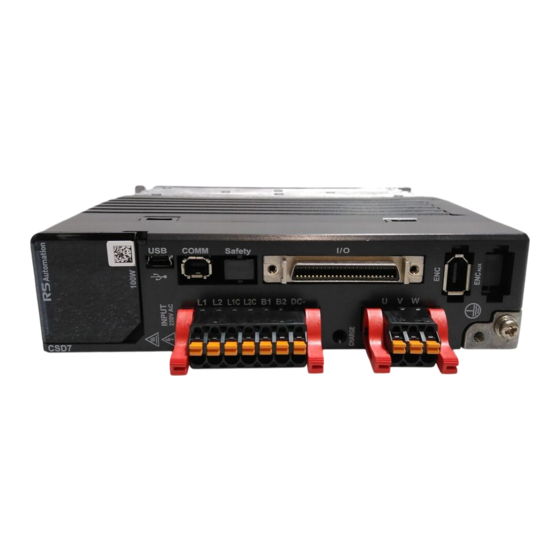
OEMax CSD7
RS Automation OEMax CSD7 Manuals
Manuals and User Guides for RS Automation OEMax CSD7. We have
1
RS Automation OEMax CSD7 manual available for free PDF download: User Manual
RS Automation OEMax CSD7 User Manual (332 pages)
Brand:
RS Automation
| Category:
Servo Drives
| Size: 5 MB
Table of Contents
Table of Contents
5
About this Publication
13
Additional Resources
13
Who Should Use this Manual
13
Conventions Used in this Manual
14
Object Description Format
14
Number of each Digit in 7-Segment for Setting Parameters
16
Terminology
16
Notation Description
17
Manual Description Order
19
Others
19
Safety Precautions
20
Storage
20
Usage
20
Installation and Wiring
21
Maintenance and Repair
21
Transportation
21
Certificate
22
Chapter 1. Before Using the Csd7 Servo Drive
26
Each Part Name of Servo Drive
26
Model Number of the Servo Drive
27
Each Part Name of Servo Motor
28
Model Number of the Servo Motor
28
Chapter 2. Installation
29
Servo Drive Installation
30
Consideration
30
Installation Environment
35
Noise Filter and Ferrite Core
37
Servo Motor Installation
37
Before You Begin
40
Power Supply, Motor Power, Regenerative Resistor
43
Name and Function of each Terminal
43
Main Power Connector (L1, L2, L3) and Control Power
44
Connector (L1C, L2C)
44
Motor Power Cable Connector (U, V, W)
44
Regenerative Resistor Connector (B1, B2)
44
Electric Circuit Diagram
45
Using Method of Socket and Lever
47
I/O Signal (I/O)
49
I/O Connection Diagram
49
Sequence I/O Signal
51
What Is Sequence I/O Signal
51
Sequence Input Signal (Allocable)
52
Allocation Method for Sequence Input Signal
53
Sequence Output Signal (Allocable)
55
Allocation Method for Sequence Output Signal
56
Notice for Sequence Signal Allocation
58
General I/O Signal
59
General Input Signal (Fixed)
59
General Output Signal (Fixed)
60
Interface with Input Circuit of I/O
60
Sequence Input Circuit
60
Emergency Stop Input
61
Interfac with Output Circuit of I/O
62
Line Drive Output
62
Photo-Coupler Output
62
Specification of STO (Safe Torque Off)
64
General Specification for STO Input/Output
64
Electric Specification for STO Input/Output
64
Specification of Sto
64
Timing Chart
65
STO Wiring
65
Encoder Wiring
67
Encoder Signal Specification
67
Encoder Connector Specification
67
Connection Diagram of Encoder Signal
68
General Articles Wiring
69
Precautions
69
I/O
69
Fuse Selection for the Drive
70
Noise Protection
71
Wiring When Multiple Drives Are Used
74
Chapter 4. Operator, Basic Setting and Commissioning
77
Before You Begin
78
About Servo-ON Signal
78
Operator
81
Name and Function of each Part
81
Icons for the Key Buttons
82
Structure of the Entire Mode
83
Status Display Mode
84
Parameter Setting Mode
86
User-Defined Parameter Setting Mode
87
Monitor Mode
88
Basic Setting
90
Overview of the Basic Setting
90
Control Mode Setting
90
Startup
91
Before Startup
91
Startup
92
Chapter 5. Ethercat Communication
96
Ethercat Slave Information
96
Set Node Address
96
Check and Set Node Address
96
Definition of Node Address
97
LED State
97
Reference Model
99
Structure of Canopen over Ethercat
101
Ethercat State Machine(ESM)
102
Esm
102
Bootstrap State
104
PDO (Process Date Object)
105
Set PDO Mapping
105
Set Sync Manager PDO Assignment
106
Default PDO Mapping
107
SDO (Service Date Object)
111
Abort Code
111
Sync by Distributed Clock (DC)
112
Communication Cycle (DC Cycle)
112
Related Object
112
Communication Timing
113
Chapter 6. Cia402 Drive Profile
115
Tate Achine
115
State Machine
116
State Definition
117
State Machine Control Command
117
Status Display
118
Related Object
118
Mode of Operation
119
Cyclic Synchronous Position Mode (CSP Mode)
119
Cyclic Synchronous Torque Mode (CST Mode)
121
Torque Limit Function
123
Related Object
124
Digital Input/Output
125
Related Object
125
Chapter 7. Object Dictionary
127
Object Dictionary Area Data Type
127
Object의 Description Format
129
Object Description Format
129
Object Dictionary List
131
General Objects
136
Syncmanager Communication Objects
147
Manufacturer Specification Objects
151
Monitor Mode Objects
187
Operation Mode Objects
191
Cia402 Objects
192
Befor You Begin
206
Mark Description
206
Gain Introduction
206
Inertia Ratio
209
Gain Setting Block Diagram
212
Auto Gain Setting
214
Auto Tuning
214
Off-Line Auto Tuning
214
ANF (Adaptive Notch Filter) Function
218
Manual Gain Setting
224
Gain Setting Flowchart
224
Manual Gain Setting Fort
224
Basic Gain Setting
225
Manual Gain Setting for Torque, Velocity, Position Control
228
Gains Related to Torque Control
228
Gains Related to Velocity Control
231
Gains Related to Positon Control
234
Tip to Get Fast Response
236
Position Feedforward Function
236
P/PI Mode Setting Function
237
Initial Torque Bias
243
Gain Group Switching, </G-SEL> Function
246
Gain Switching Function
247
Overview
254
Servo Fault
254
Motor Stop
254
Overtravel Input (<P-OT>, <N-OT>)
255
Dynamic Brake
256
Motor Brake Control
258
Motor Rotation
263
Overview
263
Regenerative Braking Resistor
264
Resistor
266
External Regenerative Resistor
266
Selection Criterion of Regenerative Resistor
267
Operation
268
Output
268
Torque Limit and Torque Limit
268
Host Controller
276
Overview
276
Direction Change of Encoder Pulse Output
277
Pulse Dividing Circuit
278
Ncoder
280
What Is an Absolute Encoder
280
Use of Absolute Encoder
280
Connecting with Host Controller
281
Battery
282
Reset of Absolute Encoder (0X300A, Run-10)
284
Unction
284
Before You Begin
286
Operation Mode Function
286
Jog Operation (Run-00)
287
Off-Line Auto Tuning (0X3001, Run-01)
288
Fault Reset (Run-08)
290
Absolute Encoder Reset (0X300A, Run-10)
291
Storage of 2Nd-Group Gain (Run-11)
292
Parameter Initialization (Run-12)
293
Monitor Mode Function
294
Introduction to Monitor Mode
294
Built-In Key Button Operation
297
Sag Function
298
Introduction to SAG Function
298
Detection Function of Torque Load Factor
300
Introduction to Function
300
Average Torque Load Factor & Maximum Torque Load Factor
300
Average Torque Load Factor Trigger 1 & 2 Signal
301
Load Factor
302
Chapter 10. Inspection and Protection Function
304
Inspection
304
Inspection of Motor
304
Inspection of Servo Drive
305
Part Inspection
305
Protective Function
306
Servo Warning
306
Servo Fault
308
Confirmation before Requesting for A/S
313
Appedix A. Specification and Exterior Dimensions
315
Drive Specification
315
Fuse and Contactor Recommendations
315
Exterior Dimension and Mouning Dimension
318
Appendix B. Cable and Connector Specification
323
Cable Specification for Ethercat Communication
324
Recommended Specification for Connector, Cable
324
Cable Connection Diagram
325
Usb Communication Cable
326
Advertisement
Advertisement
Related Products
RS Automation CSD5
RS Automation Categories
Industrial Equipment
Touch Panel
Servo Drives
Amplifier
Controller
More RS Automation Manuals
Login
Sign In
OR
Sign in with Facebook
Sign in with Google
Upload manual
Upload from disk
Upload from URL