Lab.gruppen iP Series IP 450 User Manual
Ip series
Hide thumbs
Also See for iP Series IP 450:
- Brochure (8 pages) ,
- Specifications (2 pages) ,
- Service manual (24 pages)
Table of Contents
Advertisement
Advertisement
Table of Contents

Related Manuals for Lab.gruppen iP Series IP 450


Summary of Contents for Lab.gruppen iP Series IP 450
- Page 1 ám=QRM= rpbo=j^kr^i=...
-
Page 2: Table Of Contents
N= `lkqbkqp= CONTENTS ...1 APPROVALS...2 WARNINGS ...2 Explanation of graphical symbols ...2 WARNING...2 CAUTION ...2 Important Safety Instructions ...2 User responsibility...3 3.5.1 Speaker damage...3 3.5.2 Speaker output hazard ...3 3.5.3 Radio interference ...3 INTRODUCTION...4 Unpacking ...4 Front Panel ...4 Rear Panel...5 REAR PANEL FEATURES ...5 Gain switch...5 5.1.1... -
Page 3: Warnings
O= =^mmols^ip= This equipment conforms to the requirements of the EMC directive 89/336/EEC, amended by 92/31/EEC and 93/68/EEC and the requirements of the Low Voltage Directive 73/23/EEC, amended by 93/68/EEC. Standard Applied P= t^okfkdp= PKN= bñéä~å~íáçå=çÑ=Öê~éÜáÅ~ä=ëóãÄçäë= The lightning symbol within a triangle is intended to alert the user to the presence of un-insulated “dangerous voltage”... -
Page 4: Radio Interference
16. Refer all servicing to qualified service personnel. Servicing is required when the apparatus has been damaged in any way such as: • Power-supply cord or plug is damaged • Liquid has been spilled into the unit • An object has fallen into the unit •... -
Page 5: Front Panel
QKN= råé~ÅâáåÖ= Carefully open the shipping carton and check for any noticeable damage. Every Lab.gruppen amplifier is tested and inspected before leaving the factory and should arrive in perfect condition. If found to be damaged, notify the shipping company immediately. -
Page 6: Rear Panel
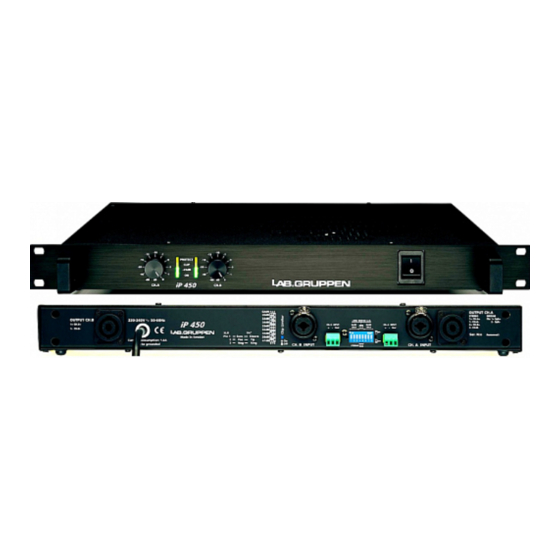
QKP= oÉ~ê=m~åÉä= Figure 2. Rear Panel 1. Output / Speaker connector The Speakon connector from Neutrik® may be unfamiliar to some users. A full description is found in the operation section. (See page 11). 2. Clip limiter switch Turns the clip limiter on (switch IN position) or off (switch OUT position). (See page 13). 3. -
Page 7: Sensitivity
the amplifiers. There are eight positions with different gain, from 20dB to 41dB in 3dB steps. See the different settings for the DIP-switches in the table below. The three switches to the very left are for channel B, and the three to the very right are for channel A. -
Page 8: Tandem Mode
Reverse operation of Channel B. RKPKP= q~åÇÉã=ãçÇÉ= In tandem mode both channels' inputs are linked and receive the same signal. The tandem mode is active if the Link switches are in position "On". Both level attenuators are active, allowing you to set different levels for each channel. -
Page 9: Installation
S= fkpq^ii^qflk= SKN= jçìåíáåÖ= The amplifier is one rack unit high (1U) and will mount in a standard EIA 19” rack. Amplifiers may be stacked directly on top of each other. If the average power is above 1/8 of full power, spaces between units and/ or forced air cooling may be used. -
Page 10: Power Consumption
SKR= mçïÉê=Åçåëìãéíáçå= There are three ways to determine the power/current consumption of the amplifier: First, the peak current draw at full output power. Under this condition the power will blow the mains breaker within 30 seconds, or the amplifier will operate for less than 2 minutes before thermally limiting. -
Page 11: Connections
The chart below shows the heat power produced in watts, in kcal per hour, and also in BTU per hour. 1/3 Power(1) 1/8 Power (2) 1/3 Power(1) 1/8 Power (2) 1/3 Power(1) 1/8 Power (2) iP 450 8 ohms 4 ohms 2 ohms note 1 Average power with music as program source. -
Page 12: Unbalanced Inputs
They are wired in the following manner: The right jack, Channel A, has both channel A and B outputs, so it’s useful for bridging and bi-amp operation (see bridged mono operation on page 7). Channel B, carries only the channel B output. -
Page 13: Operating Voltage
U= lmbo^qflk= UKN= léÉê~íáçå=éêÉÅ~ìíáçåë= • Make sure that the power switch is set to “off” before connecting any input or output or operating the switches on rear panel. See pages • Make sure that the AC mains voltage is correct and the same as the one printed on the rear panel of the amplifier. -
Page 14: Protection Features
Apart from this single exception, Lab.gruppen recommend to leave the clip limiters switched "on" (button depressed). As a side-effect, once the amplifier comes out of a protect condition, the output level has a slow rise time –... - Page 15 In the unlikely event of on a non-user rectifiable fault, return the amplifier to your supplier or an approved service centre. Lab.gruppen cannot be held responsible for damage or injury as a result of the top cover being removed. i~ÄKÖêìééÉå== ======================== rëÉê=j~åì~ä===ám=QRM======sÉêëáçå=MKP========OMMPJMOJOR=...
- Page 16 NN=pmb`fcf`^qflkp== i~ÄKÖêìééÉå== ======================== rëÉê=j~åì~ä===ám=QRM======sÉêëáçå=MKP========OMMPJMOJOR=...
-
Page 17: Warranty
NO=t^oo^kqv= General This product is manufactured by Lab.gruppen and is warranted to be free from defects in components and factory workmanship under normal use and service for a period of three (3) years from the date of original purchase from an authorised Lab.gruppen dealer.
Need help?
Do you have a question about the iP Series IP 450 and is the answer not in the manual?
Questions and answers