Advertisement
Quick Links
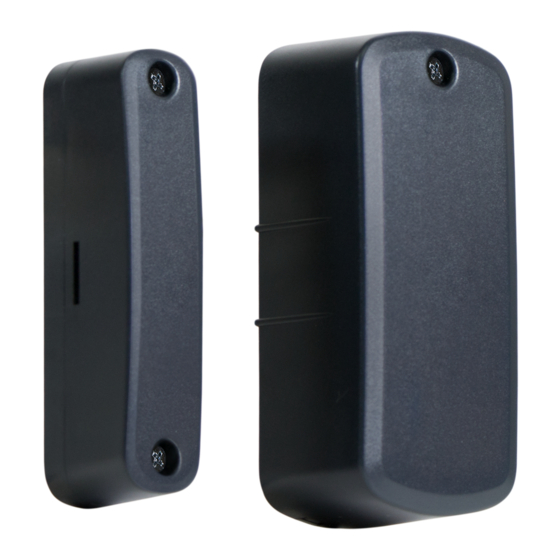
2GIG-DW30-345
OUTDOOR WIRELESS CONTACT SENSOR MANUAL
Installation Instructions
The Outdoor Wireless Contact (2GIG-DW30-345) is designed for installation on gates, doors, and other items that open and close.
It communicates with the control panel using the 345
MHz frequency. When the magnet (which is mounted
near the sensor) moves away from or closer to the
door contact's sensor, signals are transmitted to the
control panel. The sensor also has an external input
that accepts connections from Normally Closed (NC)
dry contact devices. For added protection, it is also
equipped with a cover and wall tamper.
Box Contents
• Outdoor Sensor
• Magnet
• Lithium AA Batteries (2x)
• Mounting screws
Installing the Batteries
1. Loosen the cover screw.
2. Choose any pry point, then use a small screwdriver to
remove the Sensor Mounting Plate
3. Remove the Sealing Cover.
4. Install the two Lithium Ion batteries.
5. Align the Sealing Cover to the screw hole in the sensor cover,
then press to close.
6. Engage Sensor tabs into mating holes in Sensor Mounting
Plate and swing closed. Secure with cover screw.
Mounting Guidelines
Mount the Sensor within 100 ft (30 m) of the control panel. Although the transmitter may have a range of 350 ft (106.7 m) open
air, the sensor location can have a significant effect on range. In open / unobstructed situations, the transmitter range may be
greater. In adverse wireless conditions, changing the sensor orientation may lead to improved range.
Testing the Outdoor Wireless Contact
Before mounting the Outdoor Wireless Contact at the desired location, perform a walk test to verify that it can establish good
Radio Frequency (RF) communication with the control panel.
Utilize a Repeater (P/N: 2GIG-RPTR1-345) if the RF communication is insufficient for the desired location.
NOTE: To fully test the Outdoor Wireless Contact, see the control panel's Installation and Programming Guide.
• Mount the device on a vertical surface (at a sufficient height) where water, snow and ice buildup won't interrupt operation.
NOTE: Adding silicone caulk surrounding the rubber wire seal on the Sealing Cover will increase protection against water.
• Mount the Magnet on the magnet sensing side of the Sensor. On wooden surfaces a gap of approximately 2" is possible.
This will be decreased when mounting on metal surfaces.
• Mount the Sensor on the stationary surface, and mount the Magnet on the moving surface.
• Mount the Magnet and Sensor parallel with one another.
• If installed on a wooden surface, mount the sensor and magnet on the inside of the structure (if possible).
NOTE: Use screws suitable for the mounting surface.
• If mounted on a curved surface, use zip ties and/or suitable screws to fasten the Sensor and Magnet.
Tamper Protection:
The tamper switch will activate if the cover is removed or if the sensor is detached from its mounting location.
out-door-sensor_batteries
SENSOR
SENSOR
MOUNTING
PLATE
SEALING
COVER
1 Copyright © 2018 Nortek Security & Control LLC
MAGNET
Pry points
Advertisement

Subscribe to Our Youtube Channel
Related Manuals for 2gig Technologies 2GIG-DW30-345


Summary of Contents for 2gig Technologies 2GIG-DW30-345
- Page 1 OUTDOOR WIRELESS CONTACT SENSOR MANUAL Installation Instructions The Outdoor Wireless Contact (2GIG-DW30-345) is designed for installation on gates, doors, and other items that open and close. It communicates with the control panel using the 345 MHz frequency. When the magnet (which is mounted near the sensor) moves away from or closer to the door contact’s sensor, signals are transmitted to the...
- Page 2 Outdoor Wireless Contact | Installation Instructions Mounting the Sensor on a Flat Surface. Mounting the Magnet on a Flat Surface. 1. Loosen the cover screw and remove the 1. Ensure that the magnet marks are aligned Sensor Mounting Plate. to the desired magnet location. 2.
- Page 3 Mounting on a Curved Surface Strap ties and cable ties used for mounting are not supplied. Recommended are: • Self-locking stainless steel strap ties (recommended) • Heavy duty Nylon 6/6 lN and Temperature Rated cable ties (0.5 inch wide) • A combination of screws and ties. Figure 1: Example: Self- Locking Stainless Steel Strap EXTERNAL WIRING - May be used with external closed contact switches.
- Page 4 REGULATORY INFORMATION Specifications This equipment has been tested and found to comply with the limits for Class B Digital Device, pursuant to Part 15 of the FCC Rules. These limits are designed to provide Wireless Signal Range 350 ft (106.7 m) open air reasonable protection against harmful interference in a residential installation.
Need help?
Do you have a question about the 2GIG-DW30-345 and is the answer not in the manual?
Questions and answers