Advertisement
DOORBELL
INSTALL INSTRUCTIONS
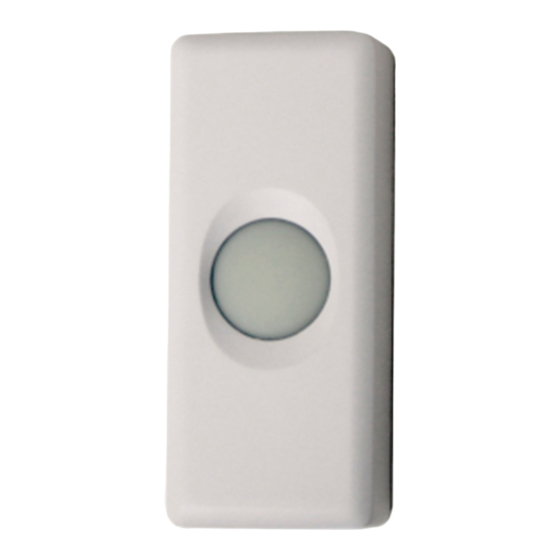
The 2GIG‐DBELL1‐345 is a dual purpose doorbell that will work with both the standard
24V wiring in the house and wirelessly with the 2GIG Control Panel. It features a
button that is fully water‐resistant and remains illuminated when the 24V house
doorbell wiring is used.
Box Contents
•
2 wood screws
•
2 machine screws
•
Doorbell sensor
•
Install Instructions
•
O‐ring
Programming
The following steps describe general guidelines for programming (learning) the sensor
(2GIG‐DBELL1‐345) into the 2GIG panel. Scroll between op ons using the ← and →
arrows. Move to the previous or next prompt by pressing the ↑ and ↓ arrows.
1
Select RF sensor # (01 to 48). Assign the Doorbell to a new zone.
2
Select RF sensor type.
(23) no response type (system will chime when the doorbell is pressed, but not trigger alarm)
3
Select RF equipment type.
(1) contact
4
Select RF sensor equipment code. Enter 1063 for the DBELL1‐345 2GIG doorbell.
5
Enter RF sensor serial number (7 digits).
Manual Entry: Type in the last 7 digits of the TX ID that is found outside of the box or on the back of the device.
Auto Entry: With the panel in Learn‐in mode (press Shift then Learn) press the doorbell button. The correct TX ID should appear. Accept
the correct TX ID by pressing ok.
Remember to press the ↓ arrow to con nue going through the 2GIG system configura on prompts.
6
Select RF sensor equipment age (0 to 1).
(0) new (product is new)
(1) existing (product already exists)
7
Select RF sensor 1 loop number (1 to 3).
(1) 1
8
Select RF sensor 1 dialer delay.
(0) disabled
9
Construct RF sensor voice descriptor. Press Insert then press any number between 002 and 255 to add a
word. For example, if you wanted to name this doorbell as "front door," press Insert then press 098 for
FRONT. Press Insert then press 058 for DOOR. Press ↓ to con nue configuring the system.
10
Select RF sensor reports (0 to 1).
(0) disabled
(1) enabled
11
Select RF sensor supervised (0 to 1).
(0) disabled (sensor does not report loss of supervision)
(1) enabled (sensor reports loss of supervision)
12
Select RF sensor chime (0 to 13).
(0) disabled (panel will NOT chime when sensor is activated)
(1‐13) enabled (selects a voice and chime to sound when sensor is activated)
13
To program another sensor click next.
14
To exit programming, click skip then end and exit. Upon exit, the panel takes a several seconds to reboot.
Testing
Before mounting the sensor, ensure that the sensor mounting location provides good RF communication to the
panel. To verify, do the following:
1
From the Installer Toolbox, select walk test.
2
Press and release the doorbell button and listen for chime or keypad beeps to determine the appropriate response (refer to the 2GIG
Control Panel Install Guide).
3
Exit the Installer Toolbox.
4
(Optional after Installing and Mounting) Verify that the household 24V AC connection is working by pressing the doorbell button to ring
the doorbell.
Installing and Mounting
If possible, locate sensors within 100 ft (30m) of the panel. While a transmitter may have a range of 350 ft (106 m) or more out in the open, the
environment at the installation site can have a significant effect on transmitter range. Although the doorbell has been designed to withstand
weather, avoid mounting it in areas where it will be exposed to extreme moisture.
1
To remove the sensor cover, use your finger to press the tab. This disengages the clip holding the cover to the base.
2
(Optional) Pull the existing house 24 AC wiring through the hole if connecting the doorbell to existing 24V doorbell wiring.
3
Mount the 2GIG‐DBELL1‐345 using the orientation shown. Use the supplied Phillips wood screws to attach the base to the mounting
surface. Ensure that the orientation arrows are pointed up (as shown).
4
Place the supplied O‐ring around the perimeter of the base.
5
If available, attach the existing 24V AC household doorbell wiring to the board using the machine screws provided. If this step is skipped,
the doorbell will work only with the 2GIG Control Panel and the LED will not illuminate.
6
Pull the battery tab out and discard tab properly.
7
Replace the sensor cover. Ensure that the drain hole is facing down. If the cover does not snap in place, it may be upside down.
FCC ID: WDQ‐DBELL1345
Industry Canada ID: 7794A‐DBELL 1345
Advertisement
Table of Contents

Related Manuals for 2gig Technologies 2GIG-DBELL1-345


Summary of Contents for 2gig Technologies 2GIG-DBELL1-345
- Page 1 FCC ID: WDQ‐DBELL1345 Industry Canada ID: 7794A‐DBELL 1345 DOORBELL INSTALL INSTRUCTIONS The 2GIG‐DBELL1‐345 is a dual purpose doorbell that will work with both the standard 24V wiring in the house and wirelessly with the 2GIG Control Panel. It features a button that is fully water‐resistant and remains illuminated when the 24V house doorbell wiring is used. Box Contents • 2 wood screws • 2 machine screws • Doorbell sensor • Install Instructions • O‐ring Programming The following steps describe general guidelines for programming (learning) the sensor (2GIG‐DBELL1‐345) into the 2GIG panel. Scroll between op ons using the ← and → arrows. Move to the previous or next prompt by pressing the ↑ and ↓ arrows. Select RF sensor # (01 to 48). Assign the Doorbell to a new zone. Select RF sensor type. (23) no response type (system will chime when the doorbell is pressed, but not trigger alarm) Select RF equipment type. (1) contact Select RF sensor equipment code. Enter 1063 for the DBELL1‐345 2GIG doorbell. Enter RF sensor serial number (7 digits). Manual Entry: Type in the last 7 digits of the TX ID that is found outside of the box or on the back of the device. Auto Entry: With the panel in Learn‐in mode (press Shift then Learn) press the doorbell button. The correct TX ID should appear. Accept the correct TX ID by pressing ok. Remember to press the ↓ arrow to con nue going through the 2GIG system configura on prompts. Select RF sensor equipment age (0 to 1).
- Page 2 Inserting and Replacing Batteries If a supervised sensor battery is low, a low battery notification will be indicated on the control panel screen. When the 2GIG system indicates that the sensor has a low battery, replace the battery immediately. Use only the recommended replacement batteries (See Specifications). To remove the sensor cover, use your finger to press the tab. This disengages the clip holding the cover to the base. Place a small flathead screwdriver in the slot between the metal clip and battery and push it out taking care not to scratch the battery terminal. Insert the replacement battery with the + sign facing out. Verify programming and RF communication with the control panel. Replace the sensor cover to the base. WARNING: The polarity of the battery must be observed, as shown. Improper handling of lithium batteries may result in heat generation, explosion or fire, resulting in personal injuries. Replace only with the same or equivalent type of battery as recommended by the manufacturer (see Specifications). Batteries must not be recharged, disassembled or disposed of in fire. Disposal of used batteries must be made in accordance with the waste recovery and recycling regulations in your area. Keep Away From Small Children. If batteries are swallowed, promptly seek medical attention. California Only: This Perchlorate warning applies only to Manganese Dioxide Lithium cells sold or distributed ONLY in /California, U.S.A. Perchlorate Material‐special handling may apply. See dtsc.ca.gov/hazardouswaste/ perchlorate. Specifications Wireless Signal Range 350 ft, open air, with 2GIG Wireless Control Panel Code Outputs Alarm; Alarm Restore; Supervisory; Low Battery Transmitter Frequency 345.000 MHz (crystal controlled) Transmitter Frequency Tolerance ±15kHz Transmitter Bandwidth 24kHz Modulation Type Amplitude Shift Keying‐On/Off Keying (ASK‐OOK) Unique ID Codes Over one million different code combinations Supervisory Interval 70 minutes External Input Sampling Current 20 uA External Input...
Need help?
Do you have a question about the 2GIG-DBELL1-345 and is the answer not in the manual?
Questions and answers