Advertisement
Quick Links
DZIAŁANIE
Każde wejście SAT IF posiada przełącznik odpowiadający za tłumienie sygnału wejściowego. Możliwa jest korekcja w
zakresie 0, 4, 8, 12 dB.
Tor tv naziemnej wyposażony został w dwa przełączniki, dzięki czemu możliwe jest precyzyjne ustawienie poziomu sygnału.
Zakres dla pierwszego przełącznika wynosi:
0, 4, 8, 12 dB, natomiast dla drugiego: 0, 1, 2, 3 dB.
Całkowite tłumienie to suma ustawień dwóch przełączników.
Tor SAT TV sterowany jest z odbiorników abonenckich. Sygnały sterujące: 14/18V (polaryzacja pionowa/pozioma),
0/22kHz (pasmo niskie/wysokie) oraz 22 kHz Tone Burst - wybór satelity (satelita A/B). Tor TV naziemnej zasilany jest z toru
SAT – polaryzacja H (Hi oraz Lo). Tor H z kolei zasilany może być ze wzmacniacza SA91L lub z lokalnego, podłączonego do
wejścia AUX zasilacza 18V. Sygnały sterujące DiSEqC zgodne z protokołem DiSEqC 2.0 ( www.eutelsat.com).
W przypadku, kiedy odbiornik nie posiada sygnałów DiSEqC, Tone Burst tylko satelita A będzie dostępny.
SPECYFIKACJA TECHNICZNA
Nazwa
Kod
Ilość wejść
Ilość wyjść
Pasmo pracy
SAT
[MHz]
DVB-T/Radio
wyj. 1-8
SAT
Wmocnienie
wyj. 9-16
(prekorekcja
wyj.17-24
ch-ki tłumienia
wyj.25-32
przewodu) [dB]
wyj. 1-8
wyj. 9-16
DVB-T/Radio
wyj. 17-24
wyj. 25-32
Regulacja
SAT
wzmocnienia [dB]
DVB-T/Radio
Max. poziom sygnału SAT
(IMD3=35 dB) [dBµV]
Max. poziom sygnału TV
wyj. 1-8
naziemnej
wyj. 9-16
(IMD3=60dB) [dBμV]
wyj. 17-24
wyj. 25-32
Separacja wejść SAT [dB]
Separacja
pasmo SAT
wyjść [dB]
pasmo DVB-T
Pobór prądu z odbiornika [mA]
Maksymalny pobór prądu z linii H oraz
zewnętrznego źródła zasilania
Przejście DC przez złącze "AUX18 V"
Sygnały sterujące
Zakres temperatur pracy [ºC]
Wymiary [mm] / Masa [kg]
Draugystes str. 22, LT-51256 Kaunas, Lithuania, tel.: +370 37 - 31 34 44, fax: +370 37 - 31 35 55
E-mail: sales@terraelectronics.com, http://www.terraelectronics.com
MV-924L
MV-932L
R70874
R70882
9
9
24
32
950-2400
47-790
7...12
6...10
5...8
-
4...6
4...9
3...7
2...5
-
1...3
12, krok 4 dB
15, krok 1 dB
93
88
86
84
-
82
> 30
> 30
> 30
< 60
12 V ...18 V
< 160 mA przy 18 V
18 V
1 A max.
14/18 V, 0/22 kHz, tone burst lub DiSEqC 1.0,
DiSEqC 2.0 lub kompatybilne wersje
-20...+ 50
227x135x52 mm / 1.42 kg
267x135x52 mm / 1.86 kg
MULTISWITCHES MV924L, MV932L
PRODUCT DESCRIPTION
This series of multiswitches has 8 satellite TV IF inputs, one terrestrial TV input and up to 32 subscriber's outputs. They
ensure an independent access of every subscriber to any SAT IF or terrestrial input.
Multiswitches are designed for use in large SAT and terrestrial TV distribution systems.
Terrestrial TV input has LTE signal suppression filter
The housing of multiswitches meets more stringent screening requirements according to EN50083-2, class A.
The multiswitches are intended for indoor use only.
SAFETY INSTRUCTIONS
Installation of the multiswitches must be done according IEC60728-11 and national safety standards.
The multiswitches are powered from the stabilized power supply +18V. This voltage is not dangerous to life.
Any repairs must be done by a skilled personnel.
To avoid damaging of the multiswitch do not connect the supply voltage until all cables have been connected correctly.
Avoid placing the multiswitch next to central heating components, near highly combustible materials and in areas of high
humidity.
If the multiswitch has been kept in cold conditions for a long time, keep it in warm room no less than 2 hours before powering.
The ventilation should not be impeded by covering the multiswitch with items, such as newspapers, table-cloths, curtains.
From top, front and bottom of installed multiswitch must be at least 5 cm free space.
WARNING!
Before connecting cables to multiswitch, be sure that cables shield and multiswitch functional grounding
clamp have common potential. Otherwise, floating voltage can damage product. Shields of cables must be connected to
main potential equalization bus.
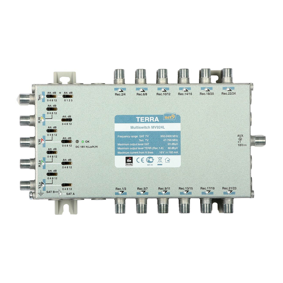
MONTAGE VIEW
The multiswitch must be fixed with steel screws Ø 4-5 mm. The screws are not included in a package.
DC voltage
Terr.TV
indicator
attenuator switch
Mounting
supports
+
Att. dB
Att. dB
Terr.TV input
0 4 8 12
0 1 2 3
Att. dB
0 4 8 12
HHi input
Att. dB
SAT A
18 V input/output
0 4 8 12
SAT B
Att. dB
0 4 8 12
Att. dB
VHi input
SAT A
OK
0 4 8 12
DC 18V H,Lo/H,Hi
SAT B
Att. dB
0 4 8 12
HLo input
Att. dB
SAT A
18 V input/output
0 4 8 12
SAT B
Att. dB
0 4 8 12
Att. dB
VLo input
SAT A
0 4 8 12
SAT B
SAT B
SAT A
Functional
Mounting
grounding clamp
supports
Four positions SAT B IF attenuator switch.
Separate attenuator switch for each SAT IF input
Four positions SAT A IF attenuator switch.
Separate attenuator switch for each SAT IF input
OPERATING
SAT IF signals must be connected as shown on the label of multiswitch to ensure correct access to SAT TV signals. It
is important to equalize average signal level from satellites. Use gain controls for each satellite line to achieve this goal.
The purpose of the control near the terrestrial TV input is to adjust optimal level of terrestrial TV signal. Maximal level must
not exceed the upper limit (see specifications), at the same time it must not be too low to avoid interference from SAT TV lines.
The subscriber's access to terrestrial TV line is permanent. Subscriber access to SAT TV lines is controlled by either
analogue control signals or DiSEqC signals, which comes from the receiver through RF cable.
Analogue control signals:
14V/18V - polarization selection (vertical/horizontal)
0 kHz/22 kHz - band selection (low/high band)
22 kHz tone burst - satellite selection (satellite A/B)
.
Outputs
Mounting
supports
A
A
A
A
A
A
B
B
B
B
B
B
Rec.2/4
Rec.6/8
Rec.10/12
Rec.14/16
Rec.18/20
Rec.22/24
Multiswitch MV924L
Frequency range SAT TV
950-2400 MHz
AUX
Terr. TV
47-790 MHz
93 dBµV
Maximum output level SAT
93 dBµV
18V
Maximum output level TERR (Rec.1-8)
88 dBµV
Maximum current from H lines
18 V
160 mA
Rec.1/3
Rec.5/7
Rec.9/11
Rec.13/15
Rec.17/19
Rec.21/23
B
A
A
B
A
A
B
A
A
B
B
B
Mounting
supports
Outputs
down position
up position
Mains
External 18 V
power supply
Advertisement

Related Manuals for Terra MV924L


Summary of Contents for Terra MV924L
- Page 1 DZIAŁANIE MULTISWITCHES MV924L, MV932L Każde wejście SAT IF posiada przełącznik odpowiadający za tłumienie sygnału wejściowego. Możliwa jest korekcja w zakresie 0, 4, 8, 12 dB. Tor tv naziemnej wyposażony został w dwa przełączniki, dzięki czemu możliwe jest precyzyjne ustawienie poziomu sygnału.
- Page 2 MULTISWITCHE MV924L, MV932L DiSEqC control signals according DiSEqC 2.0 protocol for specifications (see www.eutelsat.com). Without DiSEqC signal and tone burst only satellite A will be accessible. Multiswitch is powered from network central power supply through horizontal polarization lines (H,Lo; H,Hi). It also can be powered from external 18 V power supply connected to rear side connector "AUX 18V".
Need help?
Do you have a question about the MV924L and is the answer not in the manual?
Questions and answers