Table of Contents
Advertisement
Quick Links
dSCR (Digital satellite cable router) multiswitches SRM524, SRM544, SRM524T, SRM544T
Product description
Cascadable single cable wideband multiswitches SRM524, SRM544 and SRM524T, SRM544T are intended for the
distribution of satellite and terrestrial signals for up to 32 satellite tuners or receivers on each outputs pair.
The multiswitches have 4 passive Wideband SAT IF (for connecting 2 Wideband LNBs) and 1 passive Digital Terrestrial
TV (DTT) trunk lines.
The multiswitches have 1 DC input port and dedicated control/configuration port (see Figure 1 and chapter „Installation
instructions").
The multiswitches may be simply switched to Quattro SAT IF range input mode by dedicated switch.
SRM524, SRM524T is are cascadable single cable multiswitches with 1 pair subscribers outputs (2 outputs total).
SRM544, SRM544T is are cascadable single cable multiswitches with 2 pairs subscribers outputs (4 outputs total).
SRM524 and SRM544 have active Automatic gain control (AGC) Digital terrestrial television (DTT) path to subscribers
outputs (see Table „Technical characteristics").
SRM524T and SRM544T have passive DTT path to subscribers outputs (see Table „Technical characteristics").
The multiswitches are intended for the distribution of satellite and DTT signals for up to 32 satellite tuners or receivers on
each outputs pair and have 5 x DC power modes for convenient DC powering options (see chapter „Installation instructions").
The devices ensures an independent access for every subscriber to any SAT IF and DTT trunk line.
These multiswitches automatically detect Legacy/SCR/dSCR commands from the receiver. The dSCR switches also
feature fully automatic level control for SAT IF and DTT (SRM524, SRM544) signals, negating the need for any gain or level
adjustments in most installations.
Multiswitch is built into a zinc alloy die cast housing for extreme interference immunity. The housing of multiswitches meets
more stringent screening requirements according to EN50083-2, class A.
Control according to EN50494/EN50607 (SCR/dSCR) commands as well as Legacy (+13 V/+18 V/22 kHz) commands.
According to the standard ETSI EN 303 354 V.1.1.1, TERR TV band amplifier of multiswitch type is Launch, selectivity
clasification 0.
Safety instructions
Installation of the multiswitches must be done according IEC60728-11 and national safety standards.
The multiswitches are powered from the stabilized power supply +20 V. This voltage is not dangerous to life.
External power supply must have a short circuit protection.
Any repairs must be made by skilled personnel.
To avoid damaging of the multiswitches do not connect the supply voltage until all cables have been connected correctly.
The device shall be mounted in vertical position with RF input connectors on the top side on a wall or other nonflamable
surface.
The multiswitches must be fixed with steel screws Ø 4-4.5 mm. The screws are not included in a package.
Do not expose multiswitches to moisture or splashing water and make sure no objects filled with liquids, such as vases,
are placed near or on the unit.
Avoid placing the multiswitches next to central heating components or direct sunlight and in areas of high humidity.
No naked flame sources, such as lighted candles, should be placed on multiswitch.
If the multiswitches have been kept in cold conditions for a long time, keep it in warm room no less than 2 hours before
powering.
The ventilation should not be impeded by covering the multiswitches with items, such as newspapers, table-cloths, curtains.
The mains socket of external power supply must be easily accessible.
1
Manual in .pdf
Advertisement
Table of Contents

Related Manuals for Terra SRM524


Summary of Contents for Terra SRM524
- Page 1 The devices ensures an independent access for every subscriber to any SAT IF and DTT trunk line. These multiswitches automatically detect Legacy/SCR/dSCR commands from the receiver. The dSCR switches also feature fully automatic level control for SAT IF and DTT (SRM524, SRM544) signals, negating the need for any gain or level adjustments in most installations.
-
Page 2: Important Warnings
The SRM524, SRM544 and SRM524T, SRM544T multiswitches are intended only for indoor installation or installation in a suitable weatherproof outdoor cabinet. These multiswitches must not come into contact with moisture or be installed in areas of high humidity or heat. -
Page 3: External View
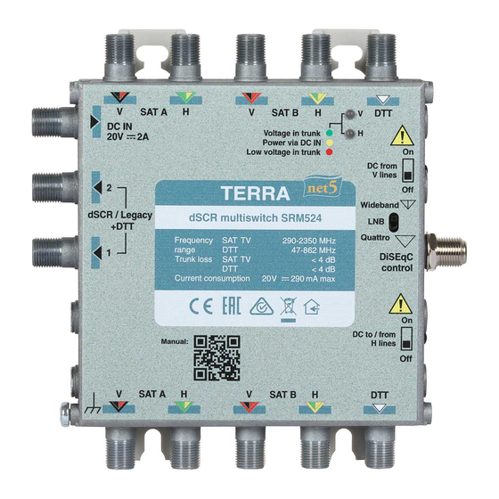
2 0 V 290 mA max DC to / from Manual: H lines SAT A SAT B Figure 1. External view of the multiswitch SRM524 SRM544 SAT A SAT B DC IN Voltage in trunk Power via DC IN Low voltage in trunk... -
Page 4: Installation Instructions
- SAT A V trunk input (SAT A VLo trunk input in Quattro LNB IF range input mode) - SAT A H trunk input (SAT A HLo trunk input in Quattro LNB IF range input mode) - SAT B V trunk input (SAT A VHi trunk input in Quattro LNB IF range input mode) - SAT B H trunk input (SAT A HHi trunk input in Quattro LNB IF range input mode) - DTT trunk input - SAT A V trunk output (SAT A VLo trunk output in Quattro LNB IF range input mode) - Page 5 Diagram of DC paths SAT A SAT B DC IN Voltage in trunk DC from V lines Wideband DC-DC converter Quattro DiSEqC control DC to/ from H lines SAT A SAT B Figure 3. Diagram of DC paths...
- Page 6 Table 1 ”DC to / from ”DC from H trunk lines” V trunk lines” Powering mode switch position switch position Warnings and notes (see Figure 1, (see Figure 1, pos.17) pos.18) Recommended as first choice. 1. Multiswitch powered from local PSU (20 V) via DC IN input WARNING: BEFORE CONNECTION (see Figure 1, pos.
- Page 7 DC voltages diagnostic LEDs meanings described in Table 2. Table 2. LED “V” LED “H” Voltage at DC from V DC to / Voltage Voltage Warnings DC IN lines switch from H lines in V line in H line and notes switch blank Yellow...
-
Page 8: Default Settings
4. Only one UB plan is set depended of delivery region, if you need another plan see chapter “Configuration” or contact TERRA UAB. 5. DC power to H / V trunk lines switches set (see Figure 1, pos. 17, 18) in position “OFF”. -
Page 9: Recommended Accessories
The default setting of the device can be changed using dedicated programmer and software. These multiswitches can be configured: 1. Up to 32 User Bands (UB) per pair outputs (SRM524 and SRM524T- total 32 UB, SRM544, SRM544T- total 64 UB) for use with STBs supporting DiSEqC commands according to standard EN50607 (dSCR). -
Page 10: Technical Characteristics
Technical characteristics Type SRM524 SRM544 SRM524T SRM544T Frequency range SAT IF wideband LNB 300-2350 MHz input LO=10400 MHz* wideband LNB 290-2340 MHz LO=10410 MHz* Quattro LNB LOlow=9750 MHz / 950-2150 MHz LOhigh=10600 MHz SAT IF output 950-2150 MHz 47-862 MHz...
Need help?
Do you have a question about the SRM524 and is the answer not in the manual?
Questions and answers