Table of Contents
Advertisement
Quick Links
Advertisement
Table of Contents

Related Manuals for Crystal Vision Indigo DT


Summary of Contents for Crystal Vision Indigo DT
- Page 1 Indigo DT Desk top boxes (Includes Indigo DT, DTA, DTAE, DTS and DTSE) Crystal Vision Ltd., Lion Technology Park, Station Road East, Whittlesford, Cambridge, CB22 4WL, England. E-mail: sales@crystalvision.tv Website: www.crystalvision.tv Tel: +44(0) 1223 497049 Fax: +44(0) 1223 497059...
-
Page 2: Table Of Contents
Crystal Vision Indigo DT User Manual R1.4 Contents Introduction Installation General Safety Summary Rack mounting and ventilation Frame connectors Connecting mains cables Connector pinout Remote control / GPI connections ... - Page 3 Frequently asked questions Appendix Active panel setup Module addresses and node numbers Specification Revision 3 Ethernet information added 16-01-07 Revision 4 Cooling mode information amended 06-07-09 Indigo DT User Manual R1.4 06/07/2009...
-
Page 4: Introduction
The DTA version has an active control panel built into it, which may remain forward facing when removed, allowing panel operation even when the cards are exposed. The Indigo DTA/DTAE Crystal Vision desk top box with front control panel removed Indigo DT User Manual R1.4... - Page 5 Warning: meet electromagnetic compatibility (EMC) requirements in this condition. The Indigo DT, Indigo DTA/DTAE and Indigo DTS/DTSE have front panel processors. These processors monitor the power rail voltage levels (+5.5V and -6.0V) and the fan speed. Status information is indicated by the state of the FAN, PSU and TEMP LEDs on the front panel and the alarm relay.
-
Page 6: Installation
To avoid electric shock do not operate this product in wet or damp conditions. To avoid injury or fire hazard do not operate this product in an explosive atmosphere. Only use this rack in conjunction with Crystal Vision modules designed for that purpose. Indigo DT User Manual R1.4... -
Page 7: Rack Mounting And Ventilation
If the optional rack ears are fitted, and the unit is installed in a standard 19" rack, cool air circulation should be available and both side ventilation grilles should be unobstructed. Indigo DT air-flow Install the Indigo DT in a standard 19" rack as follows: • Fit the optional rack ears •... -
Page 8: Connecting Mains Cables
'a' to 'f'. The functions assigned to them are dependent on the module inserted in each slot, but a typical use is as a GPI line. Refer to the documentation supplied with each Crystal Vision module to determine the actual functions assigned. -
Page 9: Power Supply Relay Connections
Remote 2 pin 14 open on fault Remote 2 pin 23 close on fault Remote 2 pin 5 The current through the relay contacts should be limited to a maximum of 200mA. Note: Indigo DT User Manual R1.4 06/07/2009... -
Page 10: Rj45 422 I/O (Statesman/Link Bus) Connector
To terminate the Statesman RS422 chain move the switch to the left, to unterminate it move it to the right. DT passive panels do not have a Term/Unterm switch and are not fitted with the second Note: panel PCB (shown at the top in this picture). Indigo DT User Manual R1.4 06/07/2009... -
Page 11: Rj45 Ethernet Connector
The two frames do not need to be the same type so any combination of Indigo 1, Indigo 2 or Indigo DT can be used. The only exception to this is the Indigo 4 frame, which cannot be linked to other frames, as the card count will exceed the maximum. -
Page 12: Frame Linking Configurations
Due to the compact nature of the 1U frame the Statesman and frame link buses share the same RJ45 rear frame connector. Because of this special care must be taken when making certain combinations of interconnected frames. Indigo DT User Manual R1.4 06/07/2009... - Page 13 All the wiring is pin to pin. Pins 16 and 7 should use one twisted pair, pins 17 and 25 the other. The screen should be connected to pin 6 on both connectors. Indigo DT User Manual R1.4 06/07/2009...
-
Page 14: Setting Frame (Desk Top Box) Addresses
Statesman system, or if multiple control panels connect to a single frame via one multidrop cable. Statesman will display the Hex switch settings 0 to E as frame addresses 1 to F. Switch setting F will be displayed as frame address 10. Indigo DT User Manual R1.4 06/07/2009... -
Page 15: Ethernet Control
This allows the Statesman PC control system or remote active control panels to control a large number of the Indigo Ethernet series frames over a local area network. Statesman control over the Ethernet of Indigo frames Indigo DT User Manual R1.4 06/07/2009... -
Page 16: Board Settings
Description Flashing This LED will flash to indicate activity. Data Link Normally lit This LED will be lit whenever the frame is connected to an Ethernet network. Indigo DT User Manual R1.4 06/07/2009... -
Page 17: Setting Up And Connecting
From this web page you are able then to change the IP address manually or automatically if DHCP is available. A frame serial number may also be entered. Indigo DT User Manual R1.4 06/07/2009... - Page 18 (second line in status list), this is the setting of the frame address switch. Rotate this switch to something other than the number displayed. Refreshing the browser will then reflect this change so verifying that the correct frame is being communicated with. Indigo DT User Manual R1.4 06/07/2009...
- Page 19 Confirmation Window Should an incorrect IP address be added an error dialogue box will be displayed indicating the likely cause of the error condition. Indigo DT User Manual R1.4 06/07/2009...
-
Page 20: Adding A Frame Serial Number
Once the desired serial number has been entered, press the ‘Store’ button to save it to memory. Should the chosen serial number contain an error or be out of range, an error dialogue box will be displayed. Error dialogue box Indigo DT User Manual R1.4 06/07/2009... -
Page 21: Installing Crystal Vision Modules
Serial number successfully added 2.8 Installing Crystal Vision modules The Indigo desk top boxes each have two slots for Crystal Vision video or audio cards. Signal connections are made through single or double rear modules. An optimal rack mount kit IDT-RK allows the 1U Indigo desk top box to be mounted into a 19"... -
Page 22: Module Positions
Removing modules To remove signal modules simply pull on the handle and withdraw them from the frame, with the retaining bracket removed. All Crystal Vision cards can be inserted and removed whilst the frame is powered without damage. Rear connectors The frame will be supplied with an appropriate selection of rear connectors for any cards installed in it at the time of order. -
Page 23: Fitting Rear Connectors
Refit a half size EMC cover if required and replace the retaining bars The Indigo DT with one half-size EMC cover and an RM01 connector fitted to slot 1 To maintain product safety and EMC compliance the rear of the frame should be... - Page 24 Quiet mode is dependent on the frame temperature being below 45°C and not being in Note: an alarm state. Although it is possible to operate the frame with the front panel open, the frame may not Warning: meet electromagnetic compatibility (EMC) requirements in this condition. Indigo DT User Manual R1.4 06/07/2009...
-
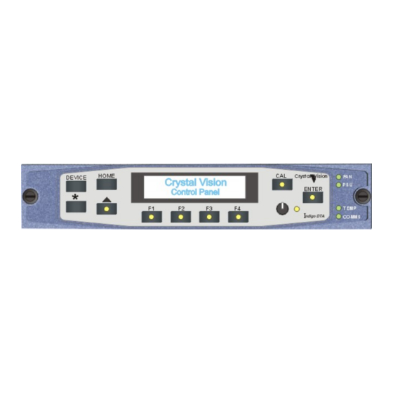
Page 25: Operating The Active Panel
Indigo 1 or Indigo 2 Turn the panel rotary knob to scroll through the available modules. Press ENTER to display information for the selected module. The Indigo PIC will display frame temperature in degrees centigrade. Indigo DT User Manual R1.4 06/07/2009... -
Page 26: Node Numbers
Operating the active panel Node numbers Whilst most Crystal Vision cards have their unique card location address assigned automatically older cards and frames use a 'node' switch on each card. In all of the current frames, this node switch should be set to zero (factory default). -
Page 27: Trouble Shooting
PSUs by pressing Enter when those devices are listed in Device view. Power supply related faults operate a relay, the contacts of which are brought out to the Remote 2 connector. These contacts can be used to operate external indicators as desired. Indigo DT User Manual R1.4 06/07/2009... -
Page 28: Panel Diagnostics
This switch should be left in the 422 position. See Reading COMMS mode and status below for further help. The first expression in the bottom line gives the Statesman rack address = hex switch setting + 1. Press CAL to exit the frame diagnostics menu. Indigo DT User Manual R1.4 06/07/2009... -
Page 29: Maintenance
IEC connector using the tab visible at the bottom of the connector depression • Remove the defective fuse and replace with either the spare fuse or with a 5A, 250V time delay fuse • Replace the fuse drawer and reconnect the power cord Indigo DT User Manual R1.4 06/07/2009... -
Page 30: Software Upgrades
Note. The Indigo DTAE and DTSE front panel does not have a removable EPROM. Software upgrades are done via the Ethernet connection. See the Indigo active front panel manual for information concerning remote software up-loading. Indigo DT User Manual R1.4 06/07/2009... -
Page 31: Frequently Asked Questions
Check that the 422/TCP panel switch is in the RS422 position Can both panels in a frame pair have active (or Statesman) panels? No, only one frame in a frame pair can have an active front panel Indigo DT User Manual R1.4 06/07/2009... - Page 32 The password is used in the resulting panel lock menu (Locked Password = ) to unlock it Why doesn't the switch on the front panel that sets the slot address work? Changing this switch only takes effect the next time the front panel is powered up Indigo DT User Manual R1.4 06/07/2009...
-
Page 33: Appendix
Comment Front Panel Company Rotate the shaft encoder to select from list Crystal Vision Press ENTER to pass over menu 4 and re-boot the panel. The front panel should now boot up as normal. Indigo DT User Manual R1.4 06/07/2009... -
Page 34: Module Addresses And Node Numbers
1.14 2.14 PSU in 1U frames Most Crystal Vision cards have their unique node or card location address assigned automatically by the panel processor based on the slot occupied in the frame and the Upper/Lower range address setting. Older cards may have a special 16-position node switch for use with older frames such as the FR2-12 or FR1-6. -
Page 35: Specification
D-Type connector and RJ45 connector) Ethernet control capable (for future upgrade) Statesman and active frame can control a second passive frame One or two passive frames can be controlled via a remote active panel Indigo DT User Manual R1.4 06/07/2009...
Need help?
Do you have a question about the Indigo DT and is the answer not in the manual?
Questions and answers