Table of Contents
Advertisement
Quick Links
Advertisement
Table of Contents

Related Manuals for Crystal Vision SW808 Controller-48V


Summary of Contents for Crystal Vision SW808 Controller-48V
- Page 1 SW808 Controller-48V 48V 1U control panel for the SW808 Crystal Vision Ltd., Lion Technology Park, Station Road East, Whittlesford, Cambridge, CB22 4WL, England. E-mail: sales@crystalvision.tv Website: www.crystalvision.tv Tel: +44(0) 1223 497049 Fax: +44(0) 1223 497059...
-
Page 2: Table Of Contents
Crystal Vision SW808-48V User Manual R1.3 Contents Introduction The SW808 Controller-48V panel Installing the SW808 Controller-48V Connecting supply cables Controller to frame remote wiring Using Controller GPIs SW808 Controller-48V operation ... - Page 3 Setting the reference termination Rear modules and signal I/O Selecting the reference on the RM20 Enabling the SW808 Controller-48V for GPI control Using module GPIs Problem solving Basic fault finding guide ...
-
Page 4: Introduction
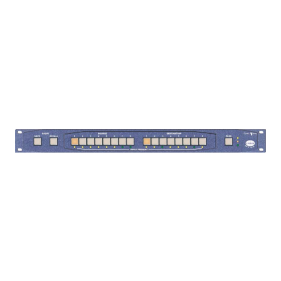
16 snapshots of the router table may be captured as presets for later recall. Control is available from the SW808 Controller-48V panel, Statesman, an active control panel or the card edge. Names may be assigned to inputs and outputs from Statesman and active control panels. - Page 5 Introduction The SW808 Controller-48V The SW808 Controller-48V is a dedicated 1U panel to control a single SW808 8 x 8 routing switch, with dedicated buttons for each of the eight sources and eight destinations. SW808 Controller-48V 8 x 8 router panel Control is quick and easy: select output, select input and press the 'take' button.
-
Page 6: The Sw808 Controller-48V Panel
2 The SW808 Controller-48V panel The SW808 Controller-48V panel is designed to control the SW808 8 x 8 routing switch using a RS422 serial link. The controller has dedicated buttons for each of the eight sources and eight destinations together with a TAKE button and Salvo SAVE and RECALL buttons. -
Page 7: Connecting Supply Cables
Statesman control at the same time as Controller access. Connecting supply cables To connect the SW808 Controller-48V to a DC supply proceed as follows: The 48V range of Indigo controllers has been designed to run in both positive and negative earth situations. -
Page 8: Controller To Frame Remote Wiring
Crystal Vision The SW808 Controller-48V panel Controller to frame remote wiring The connection from the control panel to the appropriate frame remote connector has a cable with a D-Type plug at one end and an RJ45 connector at the other. -
Page 9: Using Controller Gpis
GPI 4 will be low. This tally will follow destinations 1 and 2; no matter from where the routing is updated. The pinout for the 26 way D-Type connector at the rear of the SW808 Controller-48V panel is as follows: SW808-48V User Manual R1.3... -
Page 10: Sw808 Controller-48V Operation
2.2 SW808 Controller-48V operation To use the SW808 Controller-48V proceed as follows: • Connect the SW808 Controller-48V panel to a Crystal Vision frame with a SW808 module installed as explained in the previous section • Power the Controller panel - the panel will automatically search for a SW808... -
Page 11: Changing Cross-Point Assignments
Crystal Vision The SW808 Controller-48V panel Changing cross-point assignments To change routing first press the destination button and then the new source button. The new source button will flash and the TAKE button will light. Then press the TAKE button and the new routing will be updated on the SW808. - Page 12 Crystal Vision The SW808 Controller-48V panel To recall a salvo press RECALL, select a memory location and then press RECALL again to confirm, or any other button to cancel. Recalling a salvo: • Press RECALL – all source and destination buttons flash •...
-
Page 13: Statesman
Statesman 3 Statesman The Crystal Vision Statesman PC control software is designed to control a range of Crystal Vision modules via serial control from a PC. Statesman provides a user friendly means of configuring and operating Crystal Vision modules with the benefit of “see-at-a- glance”... -
Page 14: Routing Video
Crystal Vision Statesman Routing video Active cross-points are always shown in red and new cross-point assignments not yet confirmed with the salvo button are shown in brown. SW808 routing Multiple routing is accomplished simply by selecting more than one cross-point before clicking the salvo button. -
Page 15: Selecting The Reference
GPI control is limited to recalling presets or macros. GPI control cannot be used at the same time as the SW808 Controller-48V panel as both use the same physical control lines. Please refer to the installation chapter for more information on using GPIs. -
Page 16: Using Presets
GPI operation. Enable GPI controls preset recall when finished if required. Note: Other interfaces such as the SW808 Controller-48V, the card-edge or an active control panel may also interfere with saving or recalling presets. Using macros Up to 16 macros may be recorded and recalled from Statesman, the card edge control or by external GPIs. - Page 17 Note: Other interfaces such as the SW808 Controller-48V, the cards edge or an active control panel may also interfere with saving or recalling macros. SW808-48V User Manual R1.3...
-
Page 18: Using The Active Control Panel
Note: passwords cleared prior to using the panel for the first time. At power up, the two line 20-character screen will display ‘Crystal Vision’ followed by the firmware version number for the control panel. All eight-control panel keys LEDs will illuminate. - Page 19 When the desired card is selected press the ENTER key to access that card’s home menu. SW808 home menu In all current Crystal Vision frames the node address is coded into the back plane giving Note: a unique node address for each slot. The node address is typically one less than the locations number.
-
Page 20: Navigating The Display
• Rotary control – shaft encoder used to select options or change assigned data values Please refer to the Crystal Vision Control Panel manual for details of the panel setup, Note: lock panel and diagnostic menus. 4.2 Updating the display The values displayed on an active front panel are only updated when an adjustment is made and when changing menu level. -
Page 21: The Sw808 Menu Structure
Crystal Vision Using the active control panel 4.3 The SW808 menu structure The main top-level menus for a module are obtained by pressing the F1, F2, F3 and F4 keys from that module’s home menu. Menu keys are illuminated when active and when further menus are available. -
Page 22: Salvo And Take Functions
Crystal Vision Using the active control panel 4.4 Salvo and take functions Pressing F1 from the home menu will bring up the route menu. The route menu provides a take function to set cross-point assignments individually and a salvo function to set multiple cross-points at once. -
Page 23: Presets And Macros
Crystal Vision Using the active control panel 4.6 Presets and macros Pressing F3 from the home menu will bring up the presets menu. Use this menu to select presets or macro menus. Presets are snapshots of the entire routing table, whilst macros are custom-built tables for selected cross-points (similar to saveable salvos). -
Page 24: Configuration
Crystal Vision Using the active control panel 4.7 Configuration Pressing F4 from the home menu will bring up the Configuration menu. Use this menu to rename inputs and outputs or to recall factory settings. Configuration menu structure Description F1 selects Dig (digital) or Anl (analogue) reference... -
Page 25: Card Edge Operation
Crystal Vision Card edge operation 5 Card edge operation Once the start-up initialisation procedure is complete, the SW808 card can be controlled or configured from the card edge, active control panel or the Statesman PC interface. This chapter will concentrate on the card edge controls. -
Page 26: Default Mode - Input Status
Crystal Vision Card edge operation Preset / Macro menu functions Select preset/macro functions with the four way piano switch bank levers as follows: Menu switch Function • Default – all levers ON (DOWN) • Preset or macro recall on low to high transition (UP then DOWN) •... -
Page 27: Using Interactive Mode
Crystal Vision Card edge operation 5.3 Using interactive mode The interactive mode allows cross-point assignments to be made individually. To change cross-point assignments immediately proceed as follows: • Set menu lever 4 (Set) DOWN • Set menu lever 1 (Load) DOWN to enable ‘immediate take mode’... -
Page 28: Saving And Recalling Macros
Crystal Vision Card edge operation To recall a snapshot of all cross-point assignments as a preset proceed as follows: • Select a preset using the output HEX switch (selections are 1 to 15, and 0 which selects 16) • Set preset/macro menu lever 3 (MACRO)UP •... -
Page 29: Installation
Crystal Vision Installation 6 Installation Up to six SW808 double slot modules may be fitted in a 2U frame depending on the choice of rear connector. Two types of rear connector provide system flexibility by allowing a mix between access to all connections and maximum module packing density. -
Page 30: Rear Modules And Signal I/O
Crystal Vision Installation 6.3 Rear modules and signal I/O The RM19 full height rear connector allows access to all eight outputs and inputs but only three SW808 modules can be fitted in a 2U frame. The double slot RM19 accommodates six SW808 modules in a 2U frame, but only provides access to three outputs. -
Page 31: Selecting The Reference On The Rm20
SW808 showing configuration jumper links RS485 control (SW808 Controller-48V) To enable the SW808 Controller-48V to use RS485 communications, ensure that the four jumpers PL4, 5, 6 and 7 are all positioned towards the edge connector. Controller operation is explained in the SW808 Controller-48V panel chapter. -
Page 32: Using Module Gpis
Crystal Vision Installation 6.6 Using module GPIs Each slot has an associated set of GPI connections for remote control and external status outputs on the frame rear-panel remote connectors. For convenience, GPI lines are associated with reference codes ‘a’ to ‘f’ in the connector pin-out tables for each frame. - Page 33 Crystal Vision Installation GPI connections 4U frame GPI Connections GPI lines ‘a’ to ‘f’ of each card connect to one of eight rear remote connectors as follows: Slot no. ‘a’ pin ‘b’ pin ‘c’ pin ‘d’ pin ‘e’ pin ‘f’ pin...
- Page 34 Crystal Vision Installation 2U Indigo and FR2AV GPI Connections GPI lines 1 to 6 of each module are brought to one of the four remote connectors at the rear of the frame as follows: Slot GPI 'a' GPI 'b' GPI 'c'...
- Page 35 Crystal Vision Installation DTB-AV desk top box GPI connections GPI lines ‘a’ to ‘f’ of each module connect to the rear remote connector as follows: Slot no. ‘a’ pin ‘b’ pin ‘c’ pin ‘d’ pin ‘e’ pin ‘f’ pin Remote connector is 15 way normal density D-Type socket. Frame ground is pin 15.
-
Page 36: Problem Solving
Crystal Vision Problem solving 7 Problem solving Board edge LEDs provide status reporting and may be useful when fault finding. SW808 status LEDs Inputs present LED functions in default mode (all piano switch levers UP): Colour and function in normal mode... -
Page 37: Basic Fault Finding Guide
Check that a valid external reference is supplied and that either frame or field switching has been selected (card edge menu lever 6 in the UP position). Remote operation from an active panel (not SW808 Controller-48V) has failed Check that the remote mode is selected with menu lever 2. -
Page 38: Replacing The Supply Input Fuse
Problem solving Replacing the supply input fuse The supply-input fuse is fitted inside the SW808 Controller-48V module. The fuse can only be accessed once the top cover has been removed from the controller module. The sequence for replacing the fuse is as follows: - •... -
Page 39: Specification
Crystal Vision Specification 8 Specification General Dimensions 100mm x 266mm module with two DIN 41612 connectors. Weight 268g. Power consumption 10.5W. Inputs 8 x SDI /DVB-ASI 270Mb/s serial digital to EBU Tech 3267-E and SMPTE-259M. DVB-ASI to EN 50083-9. Cable equalisation >200m Belden 8281 or equivalent (SDI). - Page 40 Specification GPI inputs Operation Active: connect to ground. Inactive: high impedance or 3 to 35 volts. Input current <500µA. SW808 Controller-48V Dimensions 482mm wide (19 inches), 44.5mm high (1U), 90mm deep Weight 1.5 kg. Power Supply 40-75V 14W– built in.
Need help?
Do you have a question about the SW808 Controller-48V and is the answer not in the manual?
Questions and answers