Advertisement
Quick Links
Advertisement

Summary of Contents for AXMINSTER WORKSHOP AW1400B
- Page 1 Code 107710 Original Instructions AW1400B Bandsaw AT: 10/08/2022 BOOK VERSION: 11...
- Page 2 Operating Instructions 19-20 Changing the Saw Blade 20-21 Routine Maintenance Machine Footprint Bandsaw Blade Information 24-25 AW1400B Bandsaw Blades Bandsaw Trouble Shooting/Accessories UJK Technology Bandsaw Buddy Exploded Diagrams/Lists 28-29-30-31 Wiring Diagram EU DECLARATION OF CONFORMITY Cert No: MJ3420, MJ3425, EU Declaration of Conformity...
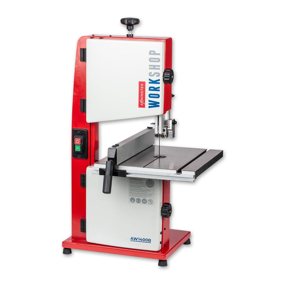
- Page 3 WHAT’S INCLUDED Quantity Item Part Model Number AW1400B Craft Bandsaw Bandsaw Blade 1,400mm Long 6mm 6TPI (Mounted on the saw but not tensioned) Table Fence Rail Fence Assembly Mitre Fence (Optional Accessory) Code: 102919 Push Stick Fence Rail Scale Strip (see pages 17-19 for mounting instructions)
- Page 4 WHAT’S INCLUDED Optional Mitre Fence Code: 102919...
- Page 5 GENERAL INSTRUCTIONS FOR 230V MACHINES The following will enable you to observe good • Leave machine unplugged until work is about to working practices, keep yourself and fellow workers commence. safe and maintain your tools and equipment in good • Always disconnect by pulling on the plug body working order.
- Page 6 SPECIFICATION Code 107710 Model AW1400B Rating Workshop Power 250W 230V 1ph Blade Speed 800 m/min Blade Length 1,400 mm Blade Width Min/Max 4.8 mm (3/16") to 9.5 mm (3/8") Max Width of Cut 200 mm Max Depth of Cut 80 mm...
- Page 7 ASSEMBLY Fig 01 Fitting the Fence Step 1 Locate the fence rail (C), fence assembly (D), four M8 bolts (I) and washers (J). Place a washer over the end of each bolt and lightly screw the bolts into the threaded holes beneath the front of the table (B), see fig 04.
- Page 8 ASSEMBLY Step 3 Locate the fence assembly (D). Lower the Fig 09-10 fence over the table until the clamping lever assembly slots into the fence rail’s “T” slot. NOTE: Make sure the clamping hook to the rear of the fence (D) has engaged over the rear of the table. Twist the locking lever clockwise to adjust the clamping tension.(two rotations should be adequate) then press down the lever to lock the fence in...
- Page 9 ILLUSTRATION AND PARTS DESCRIPTION Blade tensioning knob Upper wheel door Upper door locking knob Upper blade guide and guard Guide fence Blade ON/OFF buttons Fence guide rail Saw table ‘T’ slot for mitre fence Lower wheel door Lower door locking knob Table insert...
- Page 10 ILLUSTRATION AND PARTS DESCRIPTION Optional mitre fence assembly (A) Table levelling stop bolt ON/OFF NVR switch assembly Index and pointer (B) Blade guide adjusting knob (A) Tracking control knob (A) Blade guide clamp (B) Tracking control butterfly lock (B) Blade tensioning knob Tilt quadrant (A), Tilt scale (B) Tilt scale pointer and adjusting screw (C)
- Page 11 ILLUSTRATION AND PARTS DESCRIPTION Main saw frame Tracking control knob and lock Upper blade guide adjusting knob Upper blade guide clamp Power cable Saw table Tilt mechanism Tilt mechanism clamp Motor assembly Motor air vents...
- Page 12 ILLUSTRATION AND PARTS DESCRIPTION Lower blade guide assembly (A) Upper blade guide assembly (A) Guide bearing & adjustment caphead bolt (B) Guide bearing locking grub screws (B) Guide bearing locking grub screws (C) Guide bearing adjustment caphead bolts (C) Rear thrust bearing & clamping bolt (D) Rear thrust bearing and clamping bolt(D) Guide assembly fore and aft clamping bolt (E) Guide assembly fore and aft clamping bolt (E)
- Page 13 ILLUSTRATION AND PARTS DESCRIPTION Upper door micro switch Upper saw wheel Upper wheel mounting Blade guide assembly Fence clamping lever Saw table slot Lower saw wheel Lower door micro switch Saw wheel brush Dust extraction outlet...
- Page 14 SETTING UP THE SAW Fig 12 DISCONNECT THE SAW FROM THE MAINS SUPPLY! Tensioning and tracking the blade Make sure both top and bottom blade guide Blade are well clear of the blade. Tyre Open the front covers fully, giving good access to the top compartment of the saw and good visibility into the bottom compartment, see page 13.
- Page 15 SETTING UP THE SAW Check that the blade is perpendicular to the table. If it Checking the table is square is not, try resetting the table. If the preset table stop has been fitted, proceed as follows:- If it is still not correct, loosen the locking nut and adjust the bolt until perpendicularity is achieved, see Loosen the lift and shift handle clamping the tilt fig 16.
- Page 16 SETTING UP THE SAW Fig 24-25 DISCONNECT THE SAW FROM THE MAINS SUPPLY! Guide assembly Setting the Blade Guides Lower the upper blade guide to approximately 1 ”(38mm) above the table by loosening the blade guide height clamp and turning the adjusting knob. Clamp in place, see figs 21-22.
- Page 17 SETTING UP THE SAW Fig 27 Setting the Fence Scale NOTE: MAKESURE THE TABLE AND FENCE IS SQUARE TO THE BLADE! The fence scale strip does not come pre-mounted to the fence rail and need to be stuck in place. NOTE: Before sticking the scale down makesure the table and fence assembly is square to the blade.
- Page 18 SETTING UP THE SAW Fig 32 Fig 35 3) Check the fence is square to the table. 5) Using a pencil, ‘MARK’ the position on the guide fence rail. Remove the fence assembly. Fig 33-34 Fig 36-37 Pencil mark Scale ‘ZERO’ line 4) Using a steel rule check the fence is still in-line with 6) Peal off the backing from the scale strip, line-up the the cast iron table.
- Page 19 SETTING UP THE SAW Fig 38 Fig 39 7) Place the fence back on the table and up against the blade, lock in place. The fence should be alligned with the ‘ZERO’ line on the scale. OPERATING INSTRUCTIONS 1. Make sure you have read and fully understood the UNDER NO CIRCUMSTANCES general instructions and safety precautions that are SHOULD CHILDREN BE ALLOWED IN...
- Page 20 OPERATING INSTRUCTIONS Do not try to cut too quickly; the correct cutting 12. Remember to check the blade tension after a speed, if one could be so precise, would never see new blade has been ‘working’ for 30-60 mins. The the blade pushed back against the thrust bearing.
- Page 21 CHANGING THE SAW BLADE mounting assembly could likewise be lightly oiled. lower blade guides, see fig 31. Apply some tension If you are fitting a new blade it will have been to the blade. Turn the top wheel by hand to ensure supplied to you “folded”...
- Page 22 ROUTINE MAINTENANCE Daily Monthly • Keep the machine clean. • Open the lower and upper doors and check the condition of the tyres & the drive belt, see fig 34. • Check the saw blade for missing teeth and cracks, see fig 34. •...
- Page 23 MACHINE FOOTPRINT...
- Page 24 BANDSAW BLADE INFORMATION 10 tpi (regular) About Axcaliber Bandsaw Blades Good for cutting plywood and MDF as well as non-ferrous metals and plastics. The finish is good Axcaliber bandsaw blades are manufactured at when cutting natural timbers but the feed rate Axminster using advanced CNC machining, high should be slow and maximum depth of cut should precision digital measuring equipment and...
- Page 25 BANDSAW BLADE INFORMATION The skip tooth is provided on coarse tooth blades, those with 3, 4 and 6 teeth per inch; it has a wide 4-6tpi shallow gullet with plenty of space for waste to collect. Please note that the quality of the cut can be adversely affected by sawdust packing between the teeth.
- Page 26 AW1400B BANDSAW BLADES 1,400mm(55”) x 0.014” Standard Axcaliber Bandsaw Blades Axminster AW1400B Craft Bandsaw Width Code Width Code 3/8" 508258 1/4" 508253 3/8” 508259 1/4" 508254 3/8” 508260 1/4” 508255 3/8” 508261 1/4” 508256 1/4” 508257 BANDSAW TROUBLE SHOOTING/ACCESSORIES Please visit our website at...
- Page 27 UJK TECHNOLOGY BANDSAW BUDDY Code: 101807 INTRODUCTION • Bandsaw Buddy is a unique bandsaw blade aligning tool. Bandsaw Buddy allows you to check the alignment of the bandsaw blade to the face of the fence. Most other checks only require the use of a combination or engineer’s square.
- Page 28 EXPLODED DIAGRAMS/LISTS...
- Page 29 EXPLODED DIAGRAMS/LISTS Description Locking nut Key 5x14 Locking handle Wing nut M8 Locking handle housing Spring,lock plate Switch plate Washer 6 Switch Washer 10 Adjusting nut Motor Push stick hook Guide bracket Brush Blade tensioner Pin guide worktable Spring Ratchet lever M6 Dishing cover Bearing bolt support upper Thread rod...
- Page 30 EXPLODED DIAGRAMS/LISTS Hex.socket cap head screw M5X25 safety switch ass’y Hex.socket cap head screw M5X16 Cross recessed pan head screw M3X25 Self-lock nut M5 Mitre gauge knob Hex.nut M5 Hex.bolt M6X45 Hex.socket cap head screw M6X16 Washer 6 Spring washer 6 Mitre gauge block Thicken washer 6 Cross recessed countersunk screw...
- Page 31 EXPLODED DIAGRAMS/LISTS Connection board,lower guide Upper guide guard Washer 6 Lower guide guard Connection board,upper guide Bearing nut Bearing 625 Bearing seat,upper guide Saw frame Hex.socket set screw M6X10 WIRING DIAGRAM 31 31...
- Page 32 The Axminster guarantee Buy with confidence from Axminster! So sure are we of the quality, we cover all parts and labour free of charge for three years! axminstertools.com/3years For more information visit The packaging is suitable for recycling. Please dispose of it in a responsible manner. EU Countries Only Do not dispose of electric tools together with household waste material.
Need help?
Do you have a question about the AW1400B and is the answer not in the manual?
Questions and answers