Table of Contents
Advertisement
Quick Links
Advertisement
Table of Contents

Related Manuals for Magnamed OxyMag


Summary of Contents for Magnamed OxyMag
- Page 1 Operation Manual OxyMag – Transport and Emergency Ventilator...
- Page 2 Rua Santa Mônica 801/831 – Capuava CEP: 0671-865 – Cotia – SP – Brazil Phone/Fax: +55 (11) 4615-8500 E-mail: magnamed@magnamed.com.br Website: www.magnamed.com.br CNPJ: 01.298.443/0002-54 State Registration: 149.579.528.111 Technical Responsible: Tatsuo Suzuki Registration at CREA-SP: 0600629049 Legal Responsible: Tatsuo Suzuki 1600185-09: OxyMag – Version 3.n...
-
Page 3: Table Of Contents
Analytical Index ............. 5 VCV – V ..45 EFINITIONS OLUME ONTROLLED ENTILATION ............5 PCV – P ..47 ARNING RESSURE ONTROLLED ENTILATION ............7 PLV –L ....49 AUTION IMITED RESSURE ENTILATION ............. 7 V-SIMV – S OTES YNCHRONIZED NTERMITTENT – V ..51 ANDATORY ENTILATION... - Page 4 TECHNICAL SPECIFICATION ......79 PECIFICATIONS FOR AINTENANCE AND ALIBRATION 14.1 LASSIFICATION .......... 79 ASK FOR NVASIVE ENTILATION ..95 14.2 TANDARDS ..........79 REATHING IRCUIT ........ 95 14.3 PECIFICATIONS .......... 80 HME F ILTER ........... 95 LECTRICAL HARACTERISTICS ...... 81 PECIFICATIONS FOR ESISTANCE OF THE ONNECTING TO THE...
-
Page 5: Definitions
Definition and Care a. Definitions It is to inform the user of the possibility of injury, death or other serious adverse reaction • associated with the use or misuse of the equipment. Caution It is to inform the user of the chance to occur failure in the equipment associated with the use or misuse, •... - Page 6 This equipment should not be used in areas sensor with the type of patient informed so containing harmful substances, because it that ventilation is properly monitored. aspirates ambient air to ventilate the patient, • All parts applied to Oxymag are made of once less than 100% concentrations.
-
Page 7: Caution
Caution Caution • • Oxymag must have the ambient air intake filter Oxymag do not emit electromagnetic waves that interfere with the equipment operation in the vicinity. replaced every 500 hours of use, or at shorter •... -
Page 8: Description
Synchronized Intermittent Mandatory obesity. Ventilation with Volume Controlled cycle; Oxymag provides a mixture of ambient air and oxygen at • CPAP/PSV – Continuous Pressure Ventilation with concentrations adjusted by the operator using the accurate oxygen Pressure Support; concentration System using the venturi principle. In addition, it •... -
Page 9: Optional Items Compatible With The Products
Pulmonary ventilation may be performed in the following conditions: • • In emergency medicine for service in the field, primary Intra-hospital transportation: The patient can be care, rescue in which the patient can be transported by transported internally, from one to another department; land or air, including helicopters;... -
Page 10: Unpacking The Product
✓ If the package is found damaged, please report of components. immediately the Responsible carrier and MAGNAMED and DO NOT open the package. : List of components for Oxymag Table 1 List of components for Oxymag OXYMAG POWER OUTLET 12V... -
Page 11: Parts And Accessories
03 Silicon line, 03 Flow sensors (1 Adult; 1 Pediatric, 1 Neonatal) Part Number 1600185-NE-22-RR Part Number 5001748 Quantity: 1 unit Quantity: 1 unit QUICK GUIDE OXYMAG FAMILY Part Number 7006467 Quantity: 1 unit 1 Accessories not available for European Union Parts and Accessories Caution •... -
Page 12: Optional Accessories That Can Be Purchased For Oxymag
Optional accessories that can be purchased for Oxymag Table 2: List of optional components for Oxymag. List of optional accessories for Oxymag STAND WITH CASTERS FOR ARTICULATED ARM WITH OXYMAG SUPPORT FOR BREATHING CIRCUITS Part Number 3802668 Part Number 1704414... - Page 13 KIT ADULT FLOW SENSORS KIT PEDIATRIC FLOW AUTOCLAVABLE SENSORS AUTOCLAVABLE • 03 Silicone Line • 03 Silicone Line • 03 Adult Flow Sensors Autoclavable • Pediatric Flow Sensors Autoclavable: Part Number 5001747 Part Number 5001746 ADULT FLOW SENSORS KIT NEONATAL FLOW AUTOCLAVABLE SENSORS AUTOCLAVABLE •...
- Page 14 IRMA AIRWAY ADAPTER, IRMA AIRWAY ADAPTER, ADULT/PEDIATRIC INFANT CE 0413 CE 0413 Part Number 1704395 Part Number 1704394 SPO2 – ADULT PEDIATRIC PULSE SPO2 – NEO PULSE OXIMETER OXIMETER SENSOR AND CABLE SENSOR AND CABLE ADAPTER ADAPTER CE 0123 CE 0123 Part Number 1704410 Part Number 1704409 HEPA FILTER FOR MECHANICAL...
-
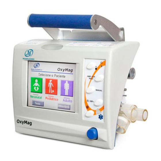
Page 15: Identification Ofc
Visual and graphical presentation of the setting parameters with touch screen. 2. KNOB BUTTON This button is used for most of the adjustments to be made in the Transport Ventilator Oxymag. • Select the parameters to be set on the display by directly touching the corresponding button;... - Page 16 16. PLUG OF POWER SUPPLY – BASE These connectors are used to connect the flow sensor. This plug is used together with the support base of Oxymag and the power supply system. The inlet is +12VDC. Note the polarity indication and the recorded voltage DC power.
- Page 17 (12.Replacing the Ambient Air Filter). • Only use power supply, parts, pieces and accessories specified by MAGNAMED listed in this manual, which were tested and approved for use in conjunction with this equipment; otherwise, this can jeopardize the operation endangering the patient or user.
-
Page 18: Description Of The Display
3. Description of the Display sidebar will fill until complete 2 seconds. Stand-by Modes button is shown with the symbol below: In the upper left corner there is the indication: ✓ Type patient selected: ADU→Adult; PED→Pediatric; NEO→Neonatal; • At the right top of the screen, there is the battery ✓... -
Page 19: Preparation For Use
Assembling Oxymag – Transport Ventilation Table 6 describes the steps to be followed by the operator (health care professional, duly trained and authorized to use the equipment) to assemble and prepare the transport ventilator. Table 6: Assembly Sequence of Oxymag Figure Assembly Sequence 1. - Page 20 Figure Assembly Sequence 5. Connect the power supply AC/DC to the □ equipment then to the mains. 6. Connect the oxygen hose to the transport □ ventilator. 7. Connect the appropriate flow sensor to the □ patient according to the figure. 8.
-
Page 21: Noninvasive Ventilation Mask
• When using Oxymag for extended time in ventilation of the patients. battery, an alarm occurs which message is • Never obstruct pressure port. -
Page 22: Power Connection
patient is not possible and provide pressure reducing valve is set to deliver appropriate means of ventilatory support. oxygen flow with pressure according to • 15.3.2 Connecting to the Oxygen Supply. Use the appropriate breathing circuit to the Pressures greater than specified may patient. - Page 23 Pull the handle bracket on the wall, just above the invisible; fixed support; Make sure that Oxymag is fixed in placed; Slide Oxymag down until it clicks into place; To remove Oxymag, perform the reverse procedure. Figure 9: Connection of the ventilator to the fixed support Below is provided the sequence to assemble the support on the 2.
-
Page 24: Checks Before Use
5. Checks Before Use The purpose of this inspection routine is to guide the user in equipment before each use or at least the beginning of each performing a simple and quick procedure to test the work period. • This equipment must pass the “Checking procedures and basic settings” to ensure the effectiveness of the equipment and the safety of the operator and patient. -
Page 25: Ventilator Settings
Ventilator Settings The ideal weight of the patient is used to calculate the ventilator • Inspiratory Flow – calculated according to TINS setting parameters to provide the best approximation to ventilate obtained; the patient. This value is calculated using the height of the patient The other parameters will have the default value: considering the Body Mass Index (BMI) of 22. - Page 26 Table 8: List of values adopted by the equipment when selecting a patient Startup button Patient type Height [m] Ideal Weight P [kg] NEONATAL 0,36 PEDIATRIC 0,95 19,8 ADULT 1,50 49,5 After startup, it is possible to change the height value within the adjustment range of the patient type set by clicking on the chart area and menu and selecting the Settings button (General Tab).
-
Page 27: Normal Startup
Normal Startup Sequence Initial screen of Oxymag – Turn on the ventilator through on-off switch on the left side of the equipment. By turning on, note that a triple “beep” goes off in conjunction with the light alarm indicator, meaning that the audible and visual alarm are operational. - Page 28 Table 10: List of parameters in the Neonatal mode Table 12: List of the parameters in the Adult mode Default Default Pinsp 15 cmH2O 350 mL Rate 40 min Rate 17 min Tinsp 0,5s Ratio I:E PEEP 5 cmH2O PEEP 5 cmH2O Flow 6 L.min...
- Page 29 the conditions described in the previous item. Tap on ALAR M alarm to be set and use the knob and confirm to set the 12. Press ALARM button and the Alarm Setting value. When the desired value is set confirm pressing the screen will appear, the figures below follow the order of knob and confirm.
-
Page 30: Test Sequence
Test Sequence The tests are essential to check if the equipment is operating as expected and make adjustments for the best possible performance. Remember to conduct initial tests before starting ventilation. • Test Sequence must be performed with the patient disconnected. Home screen - Press the Test button and the sequence of internal tests will be activated. -
Page 31: Failure Diagnosis
Failure Diagnosis The Table 13: shows the actions that can be taken to remedy the shortcomings indicated in the test sequence. The consequence column indicated what may occur if the equipment is used with failure. • If “Inoperative Device” is indicated, the use of equipment with the presence of this failure is expressly not allowed;... -
Page 32: Capnography Sensor (Etco2)
6.1 Instructions for Use The mainstream sensor IRMA was designed to be used connected to Oxymag ventilator and any other monitoring device compatible with this sensor. It has the function to monitor in real time the signal and the gas concentration. - Page 33 Figure 12: Fitting the capnography in Oxymag Attach the airway adapter to the IRMA sensor. You can hear a click when the airway adapter fits correctly to the sensor; Figure 13: Fitting airway sensor green LED indicates that the CO2 sensor is ready for use.
- Page 34 Figure 15: Connection of the airway adapter to Y-piece of the Breathing Circuit Connect IRMA 15-mm adult airway adapter to the Endotracheal Tube of the patient; Figure 16: Connecting the Airway Adapter to Part Y to the Endotracheal Tube If there is need to connect a Heat Moisture Exchanger (HME), place it between the CO2 sensor and the Endotracheal Tube. Placing the Moisture Exchanger in front of the sensor will protect the airway adapter from secretions and effects of steam, which eliminates the need to Exchange the adapter in use.
-
Page 35: Positioning Thes
6.3 Positioning the Sensor When connecting the CO2 sensor to the breathing circuit of a pediatric patient, it is extremely important to avoid direct contact between the CO2 sensor and the patient body. If not possible, for any reason, the direct contact of the sensor with any part of the child body, an insulating material must be placed between the CO2 sensor and the body. -
Page 36: Information Regarding
6.5 Information regarding LED The following table shows the possible colors displayed on the LED found on the sensor and their meanings: Table 14: Colors on the LED and their meanings Color (Status) Meaning Green (lit constantly) System OK Green (flashing) Resetting in progress Blue (constantly lit) Anesthetic Agent Found... - Page 37 transmission within the sensor window; • Replace the airway adapter if there is • The CO2 sensor was designed to be an condensation inside the adapter; adjunct device in patient monitoring. Its • Use only airway adapters produced by information must be analyzed together with PHASEIN;...
- Page 38 Attribute Specification IRMA CO : 4.5 – 5.5 VDC, Max 1.0W (power measured with 5V Electric Power Supply and less than 350mA during 200ms). IRMA CO Surface Temperature (room temperature 23°C) Max: 41°C / 106°F. Adult/Pediatric (Disposable): Adds less than 6ml dead space; Pressure drop lower than 0.3cmH 0 at 30LPM.
- Page 39 Attribute Specification Resetting recommended at each replacement of Airway Adapter. Calibration No need for specific infrared calibration. Information on the concentration is analyzed and sent every 10 seconds. Warm-up Overall accuracy in measurements: 1 minute. Rise time (at 10 l/min) ≤...
- Page 40 Effects of Gas and Steam Interference: Xe (Xenon) 80 vol% -10% measurement read. He (Helium) 50 vol% -6% measurement read. Propellant inhaler with dosimeter Not designed for use with propellant inhaler with dosimeter. OH (Ethanol) 0,3 vol% OH (Isopropanol) 0,5 vol% COCH (Acetone) 1 vol%...
-
Page 41: Oximeter (Masimo)
Oximeter (Masimo) The encapsulated pulse oximeter Masimo MS-2040 is a self-sufficient solution that enables the secure measurement even in motion and low perfusion to measure: SpO2, heart rate, perfusion index and PVI. This oximeter is compatible with all Masimo LNCS® sensors. 7.1 Operation Principle The oximeter then calculates the ratio between these two signals of arterial absorbance pulse:... - Page 42 • Risk of electric shock. Do not remove the monitor cover, except for battery replacement. The operator may perform maintenance procedures specifically described in this manual. Contact MAGNAMED technical assistance to repair this oximeter. •...
- Page 43 is approximately equal to the amount of carboxyhemoglobin present. Dyes, or any substances containing dye, changing usual pigmentation of arteries can cause read errors. • Do not use Masimo sensor during magnetic resonance imaging (MRI). Induced current could potentially cause burns. The oximeter may affect the resonance image, and the resonance unit may affect oximetry measurements.
-
Page 44: Operation Principle 7.2 Sensor Assembly
The patient has hypotension, severe vasoconstriction, severe anemia or hypothermia. o There is arterial occlusion near the sensor. o The patient is in cardiac arrest or shock 7.2 Sensor assembly Connect the oximetry sensor to the Oxymag as shown in the figure: Figure 20: Oximeter sensor assembly Manual Oxymag_Rev22... -
Page 45: Description Of Modes
8. Description of modes 8.1 VCV – Volume Controlled Ventilation Description: Set Parameters: In this mode, the ventilator controls the volume flow and cycle, i.e., at each inspiratory cycle the ventilator delivers a precise volume to the patient, • VOLUME; provided that the pressure is not limited. - Page 46 Ventilation with Inspiratory Pause, after delivery of the set volume, the ventilator maintains the exhalation stopped until complete TINS after which the ventilator cycles to exhalation, the feature is the pressure plateau formation (gap between peak and plateau depends on the airway resistance). If the pressure or flow trigger is enabled, then the ventilator tries to synchronize the beginning of the next inspiration with patient effort, according to the levels established.
-
Page 47: Ontrolled Ventilation
8.2 PCV – Pressure Controlled Ventilation Description: Set Parameters: In this mode, the ventilator controls pressure and cycles on time, i.e., at each inspiratory cycle, the ventilator reaches the set pressure and remains at this • INSP PRESSURE; level until the inspiratory time set has elapsed, the volume is, therefore, •... - Page 48 Once all ventilation parameters are set on the ventilator, it calculates TINS, TEXP based on Rate and Ratio I:E; thus obtaining all ventilation control times. 1 and 2 Pressure Controlled Ventilation – The ventilator achieves the inspiratory pressure set in the shortest time possible, and this is accomplished by controlling the inspiratory flow.
-
Page 49: Ventilation
8.3 PLV –Limited Pressure Ventilation Description: Set Parameters: In this continuous flow mode, the ventilator limits pressure and cycles on time, i.e., at • INSP PRESSURE; each inspiratory cycle the ventilator reaches the set pressure and remains at this level •... - Page 50 Once all ventilation parameters are set on the ventilator, it calculates TEXP based on Rate and TINS and, thus, obtain all ventilation control times. 1 e 2 Pressure Limited Ventilation – The ventilator seeks to achieve the set inspiratory pressure, and this is accomplished by occlusion of the exhalation valve.
-
Page 51: Intermittent Controlled Cycle
8.4 V-SIMV – Synchronized Intermittent Mandatory Ventilation – Volume Controlled Cycle Description: Set Parameters: • VOLUME; In this mode, the patient can breathe spontaneously between the • RATE; controlled cycles, with or without the use of pressure support. Controlled • INSPIRATORY TIME;... - Page 52 3 Represents a VCV (volume controlled) cycle with SIMV Period elapsed; 5 Represents spontaneous breathing cycle of the patient WITH PRESSURE SUPPORT, with cycling occurring by flow, when this reaches a value between 5% and 80% of the peak value read. Peak flow percentage at which cycling of inspiratory phase occurs to the expiratory phase is programmable.
-
Page 53: P-Simv - Synchronized
8.5 P-SIMV – Synchronized Intermittent Mandatory Ventilation – Pressure Controlled Cycle Description: Set Parameters: • INSP PRESSURE; In this mode, the patient can breathe spontaneously between the • RATE; controlled cycles, with or without the use of pressure support. The •... - Page 54 Once all ventilation parameters are set on the ventilator, it calculates TEXP based on TINS and Rate, thus obtaining all ventilation control times. 1 Represents a PCV (pressure controlled) cycle during TINS; 2 Represents a spontaneous breathing cycle of the patient WITHOUT PRESSURE SUPPORT; 3 Represents a PCV (pressure controlled) cycle when SIMV Period has elapsed;...
-
Page 55: With Pressure Support
8.6 CPAP/PSV – Continuous Pressure Ventilation with Pressure Support Description: Set Parameters: In this mode, the patient breathes spontaneously on a continuous • PEEP or CPAP; positive pressure and breathing is assisted by a Pressure Support • ΔPS (Pressure Support – PEEP); (ΔPS). - Page 56 1 and 2 Represent spontaneous cycles with pressure support at ZERO. , 4 and 5 Represent spontaneous breathing cycles of the patient with pressure support different from zero. TRISE TIME of pressure support may be adjusted so that initial flow is smoothed. 6 If the patient enters in apnea, after TAPNEA (s) the ventilator will show this condition with alarm in its message area and alarms on...
-
Page 57: Pressure Ventilation
8.7 DualPAP – Bi-level Continuous Positive Airway Pressure Ventilation Description: Set Parameters: In this mode, the patient breathes spontaneously on two continuous • P. HIGH; positive pressure and breathing may be assisted by a Pressure Support • T. HIGH; (ΔPS). Usually by analyzing the flow curve, a flow peak is seen which •... - Page 58 Once all ventilation parameters are set on the ventilator, the patient breathes spontaneously defining the ventilation control times. 1 Represents a spontaneous cycle without pressure support at P.Low (Low Continuous Airway Pressure); 2 Represents a breathing cycle with Pressure Support assist (above P.Low); 3 to 4 Represents a synchronized transition to P.High (High Continuous Airway Pressure);...
-
Page 59: Aprv -Airway
8.8 APRV –Airway Pressure Release Ventilation (mode obtained with inverted ratio in DUALPAP) Description: Set Parameters: • P. HIGH; This mode allows spontaneous cycles on 2 levels of • T. HIGH; baseline pressure and can be achieved by appropriate • P. - Page 60 Once all ventilation parameters are set on the ventilator, the patient breathes spontaneously defining the control times of ventilation. 1 and 2 Represent spontaneous cycles without pressure support at P. High (High Continuous Airway Pressure); 3 Represents the transition of P.High to P.Low (Low Continuous Airway Pressure) synchronously; 3 to 4 Represents the time T.Low in which airway pressure release is performed;...
-
Page 61: Alarms Available
Description of alarm control The alarm system of the Oxymag family ventilators are classified according to the degree of priority (low, medium, and high priority) as shown in table. Table 18: Classification of alarms according to the priority level... - Page 62 HIGH PRIORITY Delay Time Description It is triggered when the ventilation pressure is below the set alarm value as Low Maximum Pressure < 2 cycles the lower limit of pressure It is triggered when the measured volume exceeded the alarm value set as High Volume <...
- Page 63 HIGH PRIORITY Delay Time Description Restart IRMA It is triggered when IRMA CO sensor must be disconnected and re-connected < 3 seconds Change IRMA It is triggered when IRMA CO sensor must be replaced. < 3 seconds MEDIUM PRIORITY Delay Time Description It is triggered when the minute volume of the patient has exceeded the alarm High Minute volume...
- Page 64 LOW PRIORITY Delay Time Description AC input fail It is triggered when there is no electrical energy from the network < 1 second It is triggered when SpO Sensor is connected to the equipment, but is outside Sensor < 3 seconds the finger It is triggered when: •...
- Page 65 energy source must be provided immediately. The alarm will be re-initialized when connected to a source of A.C. power or external D.C. Note • The actual remaining time will depend on the battery condition and parameters used in the ventilator. b) Disconnection alarm The disconnection alarm is triggered when any kind of disconnection from the breathing circuit occurs, in order to prevent proper ventilation to the patient.
- Page 66 4. Replace the diaphragm in the correct position damaged; or replace diaphragm with a new one; 5. Failure in the electronic system of pressure control; 5. Contact Technical Assistance / Magnamed 1. Change in Patient’s Respiratory Mechanics; 1. Set new parameters for ventilatory support; Manual Oxymag_Rev22...
-
Page 67: Setting Alarms
Low Battery Alarm 2. Failure in the charging system of the internal battery, 2. Contact Technical Assistance / Magnamed; even with the presence of electric power; 1. Restore connection of the equipment to a 1. Disconnection to the power cord;... -
Page 68: Manual Ventilation Of The 9.4 Alarm Test
Adjustable alarms of capnography will be visible if the capnography is connected to the ventilator, as well as the adjustable oximetry alarms will be visible when the oximeter is connected. To change the alarm values just touch the area corresponding to the alarm limit to be set. The parameter touched will be selected indicating that is possible to change;... - Page 69 • The Alarm should be tested without a connection to the patient. • In case of failure see the Description of alarm. • Do not use the equipment if the test fail. Note • Use a gas inlet with recommended pressure. Manual Oxymag_Rev22...
-
Page 70: Cleaning And Sterilization
Cleaning and Sterilization 10.1 Equipment cleaning External ventilator surfaces External ventilator surfaces of Oxymag should be cleaned with a clean, soft cloth moistened with the enzymatic detergent. Caution • Ensure that no residue builds up in the equipment connections. •... -
Page 71: Drying
The components that get in touch with the respiratory gases must be removed for cleaning and sterilization; • Do not use abrasive agents to carry out cleaning; • Do not use alcohol to clean the plastic parts; • Do not immerse the Oxymag in any liquid; • • When sending Oxymag... -
Page 72: Processing Methods
This equipment and the parties must go through a cleaning process every time it is Caution • The accessories and components removable from Oxymag undergoing repeated operations of sterilization and cleaning may be degraded and should be replaced with new ones. 10.4 Processing methods Processing methods... -
Page 73: Preventive Maintenance
Preventive Maintenance Caution • O Oxymag should have their maintenance performed only by a qualified technician, trained and authorized by MAGNAMED 11.1 Indication of the need for periodic maintenance The equipment displays in the home screen the preventive maintenance symbol when 5000 hours or more had passed since the last maintenance. -
Page 74: Internal Sensor Of
10,000 hours at 100% O2, i.e., more than one year of continuous use. Caution • • The oxygen concentration measuring cell Replacement of the oxygen concentration should be replaced as indicated in the measuring cell should be performed only by Technical Specification (chapter 15). qualified technician, trained authorized by MAGNAMED. Manual Oxymag_Rev22... - Page 75 • user; Use only filters, parts, pieces and • accessories specified by MAGNAMED listed filter when saturated generates an increase in this manual, which have been tested and in the resistance of the ambient air inflow approved for use in conjunction with this and can make the minimum concentrations equipment;...
- Page 76 (chapter 10). Products showing signs of potential hospital contaminants will be returned without repair service in order to be disinfected prior to the service. • When sending Oxymag for maintenance or repair services: check closely the disinfection process. • Equipment visibly infected by patient fluids will be returned without carrying out maintenance or repair service.
-
Page 77: Disposal
12. Disposal Discard the removed parts of the equipment according to the protocol for disposal of parts and pieces of your institution and follow the local government recommendations regarding environmental protection, especially in the case of electronic waste or electronic parts (e.g., batteries). -
Page 78: Turning Off The Equipment
13. Turning off the Equipment The lung ventilator Oxymag is a life support equipment and must be MANDATORILY disconnected from the patient to be turned off. The equipment should be turned off in the on/off switch, identified in Figure 5. -
Page 79: Technical Specification
14. Technical Specification 14.1 Classification • NBR – IEC – 60601 Class II Equipment, energized internally, BF-type for continuous operation. Protected against the ingress of solid foreign objects with 12,5mm diameter or bigger and Splash-proof equipment - IP24. • Annex IX Directive 93/42/EEC, Rule 11 Class IIB –... -
Page 80: Specifications
320 x 240 points color Liquid Crystal DISPLAY LCD 5.7” graphic with touch screen; • Control Board with: Data presentation on the display; Serial interface RS-232C for software update; Remote Diagnostics and Remote Assistance Magnamed (ARM); Quick access keys for: ✓ HOLD; ✓ O 100%;... -
Page 81: Haracteristics
• Carrying Case with Oxygen Cylinder, optional. • Carrying Case without Oxygen Cylinder, optional. • Pedestal for Oxymag, optional. • Kit blender, optional. 1 Accessories not available for European Union Electrical Characteristics Table 21: AC/DC Converter Source – External (2402568 – POWER SUPPLY 12V WITH 4-WAY CONNECTOR) -
Page 82: Connecting To The Physical Ande
• Class IIb - According CE/93/42/CEE annex IX; • Protection Class of Breathing Accessories (Disposable or Reusable): BF type (Body Floating). Connecting to the Oxygen Supply • Oxygen Inlet –DISS male thread 9/16” 18 wires, as per ABNT NBR 11906 OPTIONAL –NIST Thread •... -
Page 83: Extreme Conditions
Item Parameter Specification Tolerance Unit Relative Humidity (w/o condensation) 15 - 95 Temperature -25 - 75 °C Storage Barometric Pressure 500 - 1200 Relative Humidity (w/o condensation) 5 - 95 Oxygen Consumption of the Cylinder under the conditions: • Vol tidal = 500 mL min/L ... - Page 84 Mode in Apnea Description Modes (1)(2)(3) (BACKUP) Volume Controlled Synchronized Intermittent Mandatory – Volume Controlled V-SIMV + PS Ventilation with Pressure Support Intermittent Mandatory Ventilation Pressure Controlled Synchronized Intermittent Mandatory – Pressure Controlled P-SIMV + PS Ventilation with Pressure Support Intermittent Mandatory Ventilation VCV, PCV (adult and pediatric) / Bi-level Positive Airway Continuous pressure with Pressure...
- Page 85 Item Parameter Specification Resolution Unit Assisted Sensitivity (Flow) OFF; 0,5 to 30,0 L.min Automatic Inspiratory Flow 0 to 150 L.min Inspiratory Flow (Neonatal) 4 to 20 L.min Cycling by Flow at Pressure 5 to 80 Support Concentration 35 to 100 0,1 to 0,7:0,01 Inspiratory Time 0,1 to 10...
-
Page 86: Parameters
Item Parameter Specification Resolution Unit 0,16 to 0,52:0,01 Height 0,16 a 2,50 0,53 to 1,08:0,01 1,09 to 2,50:0,01 Tidal Volume for values lower than 20ml is set adjusting pressure, monitoring the tidal volume in the display of the ventilator. This volume is the volume delivered to the ventilator outlet, and the user should check the absence of leaks”. -
Page 87: Parameters
The ideal weight is calculated using BMI = 22 and patient height can be changed according to the type of patient set at startup as table below: Table 27: Calculation of ideal weight x patient height Patient Type Height Adjustment [m] Ideal Weight P [Kg] Min. - Page 88 Item Parameter Range Resolution Tolerance Unit (1 cmH2O or Intrinsic PEEP at the -20 to 90 end of expiration 2% reading) Flow Measured ± (2.0L.min-1 or -150 to 150 L.min (Sensor Adult) 5% reading) Flow Measured ± (0.5L.min-1 or -50 to 50 L.min (Sensor Pediatric)
-
Page 89: System
Item Parameter Range Resolution Tolerance Unit Airway Resistance – O/L/ 0 to 200 1 mL.cmH2O Dynamic Compliance mL.cmH or 10% value 0 to 200 (C.Dyn) measured 1 mL.cmH2O Static Compliance mL.cmH or 10% value 0 to 200 (C.Stat) measured (Oxygen ±(1% in volume or... - Page 90 • ventilation in action. The equipment When the ventilator is restarted or the type operator must aware of patient is changed, alarms will assume DEACTIVATED condition of the Apnea the default values in table 30 according to Alarm (INDICATING ON THE DISPLAY). the type of patient.
- Page 91 Alarm Feature High Priority Medium Priority Intermittence frequency 1.42 hz 0.71 hz Number of saved pulses 10 pulses 3 pulses Interval between saves 5.0 s 5.1 s Sound pressure range 63.5 dBA 62 dBA Pulse frequency 688 hz 687 hz Note •...
- Page 92 Standard Alarm¹ Item Alarm Setting Limit Unit High Automatic limit OFF, 10, 20 and setting ³ Heart Frequency ² OFF;25 to 240 High ² OFF; 1 to 100 High EtCO ² OFF; 0 to 80 mmHg High CO2 inspired ² OFF;...
-
Page 93: Circuit Curve
Check Cable Enabling SpO Low Perfusion SpO2 demo Looking for pulse Concentration x Pressure in the breathing circuit curve O X Flow Pressure 5 Pressure 15 Pressure 30 Pressure 60 Flow [L/min] Figure 30: Concentration curve in function of pressure in the breathing circuit Performance Specifications Table 32: Performance specification... -
Page 94: Exhalation Valve
Specifications for Maintenance and Calibration Caution • The processing time is after stabilizing at the specified temperature and pressure. • Check the efficiency of sterilization through chemical or biological indicators. Table 33: Specification for maintenance and calibration Description Specification Tolerance Unit Item 50 cycles of steam... -
Page 95: Mask For Non -I
Mask for Non-Invasive Ventilation Specification Adult/ Pediatric connection 22 mm Neonatal connection 15 mm Breathing Circuit Specification Adult/ Pediatric connection 22 mm Neonatal connection 15 mm Resistance ≤ 0.3 mbar/L.s HME Filter Specification Adult/ Pediatric connection 22 mm Bacterial Filtration Efficiency 99,999 % Specifications for Resistance of the Expiratory Limb Table 34: Expiratory Resistance in Function of Breathing Circuit and Accessories Aggregates... -
Page 96: Pneumatic Diagram
Pneumatic diagram Figure 31: Pneumatic Scheme of the transport ventilator Manual Oxymag_Rev22... -
Page 97: Block Diagram Of
Block Diagram of Control Electronics Figure 32: Block Diagram of Electronics Manual Oxymag_Rev22... -
Page 98: Control Electronics 97 Compatibility
Electromagnetic Compatibility Changes or modifications to this equipment not expressly approved by MAGNAMED can cause EMC problems with this equipment or another. Contact MAGNAMED to receive technical assistance. This equipment has been designed and tested to comply with applicable EMC standards as described below. - Page 99 B) Guidelines and manufacturer’s statement – Electromagnetic immunity The system is intended for use in the electromagnetic environment specified below. The customer or user of the system should ensure that it is used in such an environment. Table 36: Electromagnetic environment for use of the system IEC Test Level -60601-1- Directive for electromagnetic Immunity Test...
- Page 100 Table 37: Radiated Immunity Test Level Electromagnetic environment – Guidelines Compliance Immunity Test ABNT NBR IEC 60601 Recommended separation distance Portable and mobile RF communication equipment should not be used near any part of the system, including cables, with a separation distance shorter than the recommended, calculated from the equation applicable to the transmitter frequency.
- Page 101 Table 38: Separation distance according to the transmitter frequency (m) Maximum output 150 kHz - 80 MHz 150 kHz - 80 MHz power of the Within the ISM 800 MHz – 2.5 GHz Out of the ISM bands 80 MHz - 800 MHz transmitter bands ...
- Page 102 accepted by IEC 60601- under normal (according to standard IEC 60601-1). conditions and single-failure conditions. • The operator of the electromedical system This may cause dangerous electrical must not touch the non-medical electrical shock to the patient or operator. equipment and the patient at the same •...
-
Page 103: Symbols
Symbols SYMBOLS / PORTUGUÊS ESPAÑOL ENGLISH UNIFIED TEXTS PACIENTE PACIENTE PATIENT CORRENTE CONTÍNUA CORRIENTE CONTINUA CONTINUOUS TIDAL CORRENTE ALTERNADA CORRIENTE ALTERNA ALTERNATING CURRENT (REDE) (RED) (POWER) ENERGIA ELÉTRICA ENERGÍA ELÉCTRICA ELECTRIC ENERGY WASTE – ELECTRICAL AND ELECTRIC RECOLHIMENTO DE EQUIPAMENTO RECOGIMIENTO DE EQUIPO EQUIPMENT SHALL BE COLLECTED ELÉTRICO/ELETRÔNICO FEITO DE... - Page 104 SYMBOLS / PORTUGUÊS ESPAÑOL ENGLISH UNIFIED TEXTS IDENTIFICAR OU ACONSELHAR IDENTIFICAR O ASESORAR LA TO IDENTIFY OR ADVISE CLEANING LIMPEZA OU TROCA DE FILTRO LIMPIEZA O EL CAMBIO DEL FILTRO OR CHANGING A FILTER TRAVAR TECLADO TRABAR TECLADO KEYBOARD LOCK MANTENIMIENTO MANUTENÇÃO PERIÓDICA PERIODIC MAINTENANCE...
- Page 105 SYMBOLS / PORTUGUÊS ESPAÑOL ENGLISH UNIFIED TEXTS MANUAL DE OPERATING INSTRUÇÃO DE USO INSTRUCCIONES INSTRUCTIONS FRÁGIL FRÁGIL FRAGILE FACE SUPERIOR NESTA LADO SUPERIOR EN ESTA THIS SIDE UP DIREÇÃO DIRECCIÓN PROTEGER CONTRA PROTEGER CONTRA LA FEARS HUMIDITY UMIDADE HUMIDAD SOSTENIMIENTOS DE LA QUANTIDADE SEGURA DE CANTIDAD DE SAFE STACKING QUANTITY...
- Page 106 SYMBOLS / PORTUGUÊS ESPAÑOL ENGLISH UNIFIED TEXTS FUSÍVEL FUSIBLE FUSE CONFORMIDAD CE: INDICA QUE CONFORMITY CE: INDICATES CONFORMIDADE CE: INDICA QUE EL SISTEMA ESTÁ EN THAT THE SYSTEM IS IN O SISTEMA ESTÁ EM CONFORMIDAD CON LA ACCORDANCE WITH CONFORMIDADE COM A DIRETIVA DIRECTIVA DEL CONSEJO DIRECTIVE OF THE EUROPEAN 93/42/CEE...
-
Page 107: Terms And Abbreviations
Terms and Abbreviations Table 39: List of terms and abbreviations with their descriptions Terms and Terms and Description Description Abbreviation Abbreviation Adult Ratio T.Insp by TExp Backup Apnea Mode Setting Body Mass Index C.Dyn Dynamic Compliance Infant i Alarm setting High CO inspired Man Trig Manual Trigger... - Page 108 Terms and Terms and Description Description Abbreviation Abbreviation Continuous Pressure Ventilation with VMspn Spontaneous Minute Volume Pressure Support Synchronized Intermittent Mandatory P. High High pressure of DualPAP mode V-SIMV Ventilation with Controlled Volume cycle P.Low Low pressure Vspn Spontaneous Volume Airway resistance Adjusted Tidal Volume Resistance...
-
Page 109: Statement Of Biocompatibility
This is to state, under our sole responsibility, that all materials used in parts (as defined in standard NBR IEC 60601-1) applied to Oxymag has been widely used in the medical field overtime, thus ensuring their biocompatibility. And, according to standard ISO-10993-1 Biological evaluation of medical devices — Part 1: Evaluation and testing – clause 4.2.1 –... -
Page 110: Warranty
18. Warranty The manufactured Products and marketed by MAGNAMED TECNOLOGIA MÉDICA S/A are warranted against material and manufacture defects throughout Brazil, as provided below. The warranty period for the equipment is 12 months. For batteries and accessories, the periods of 3 months, provided that retained their original features;... -
Page 111: Technical Assistance
19. Technical Assistance For maintenance, please contact our technical assistance who will indicate the service nearest you or visit our website. Manual Oxymag_Rev22... -
Page 112: Training
Training To request training, please contact Magnamed product expert team who will indicate the authorized Representative nearest you. Manual Oxymag_Rev22... - Page 113 Website: www.magnamed.com.br Email: magnamed@magnamed.com.br Manufacturer / Technical Assistance / Customer Service Magnamed Tecnologia Médica S/A Rua Santa Mônica, 801 - 831 – Bairro Capuava CEP: 06715-865 – Cotia – SP – Brasil Phone/Fax: +55 (11) 4615-8500 E-mail: magnamed@magnamed.com.br Website: www.magnamed.com.br CNPJ: 01.298.443/0002-54...
Need help?
Do you have a question about the OxyMag and is the answer not in the manual?
Questions and answers