Table of Contents
Advertisement
Advertisement
Table of Contents

Related Manuals for Amrex SynchroSonic US/50


Summary of Contents for Amrex SynchroSonic US/50
- Page 1 ® electrotherapy equipment a division of Amrex-Zetron, Inc. *Federal law (USA) restricts this device to sale by or on the order of a licensed practitioner licensed by the law of the state in which he practices to use or order the use of this device.
- Page 2 SynchroSonic US/50 User's Guide Revised August 1998 Copyright © Amrex-Zetron, Inc. 1995. All rights reserved. Printed in the United States of America The following are registered or trademarked by Amrex: Amrex ® SynchroSonic ® QuickConnect ™ Flextrode ® ® AMREX electrotherapy equipment a division of Amrex-Zetron, Inc.
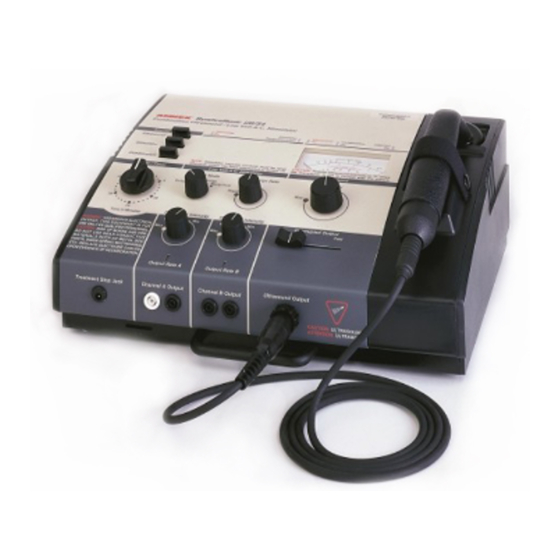
- Page 3 Thank you. . . for selecting the Amrex SynchroSonic US/50. We believe that you will find this instrument to be versatile, dependable and user friendly. The SynchroSonic US/50 provides two widely used therapeutic modalities: Low Volt AC Stimulation and Ultrasound. Each modality may be applied separately or the Ultrasound may be combined with Low Volt AC Stimulation simultaneously through the ultrasound transducer.
- Page 4 Call toll free (800) 221-9069. Save the original shipping carton and all packing materials to safely return Amrex equipment to the factory for service; repair; annual calibration, electrical and mechanical safety check. All accessories, including the ac line cord, must be included with the returned instrument.
- Page 5 Important AMREX Intensity Reset Circuit: The Amrex Low Volt AC Stimulator modality incorporates a unique safety reset function as part of the intensity control. This is to prevent any sudden or inadvertent stimulation output to the patient in the event that: The Low Volt AC Intensity control is not set to the 0/Reset position enabling the audible "click"...
- Page 6 Ultrasound—Contraindications Ultrasound should not be used in the following areas: transcerebrally; near the heart or reproductive organs; over viscera, eyes, ears, the spinal column, malignancies, the joint capsule in arthritic conditions either acute or subacute, or over total joint replacements. Ultrasound should not be used in cases of: cardiac pacemakers, pregnancy, implants, malignant or benign tumors, multiple sclerosis, arteriosclerosis or weakened blood vessels, hemophilia, thrombosis and thrombophlebitis either acute or subacute.
- Page 7 Electrical Muscle Stimulation—Contraindications Contraindicated for patients with cardiac demand pacemakers. Should not be used on cancer patients. Electrical Muscle Stimulation—Warnings Long term effects of chronic electrical stimulation are unknown. Safety has not been established for the use of electrical muscle stimulation during pregnancy.
-
Page 9: Table Of Contents
Table of Contents Part 1 Overview ..........................1 Part 2 Power Section ........................5 Part 3 Low Volt AC Stimulator Modality ..................9 Part 4 Ultrasound Modality ......................15 Part 5 US/50 General Operation and Application Procedures ..........21 General Operation Ultrasound Modality ................21 Application of Ultrasound ...................... - Page 10 viii...
-
Page 11: Part 1 Overview
Part 1 AMREX Overview The layout of the US/50 panel is logically arranged into three major sections. These sections are, from left to right: Power, Low Volt AC Stimulator and Ultrasound. US/50 User's Guide... - Page 12 Part 1 In the illustration below, dashed lines surround each of the US/50's sections. A brief description of each section follows the illustration, and Parts 2 through 4 of this manual contain detailed descriptions. US/50 User's Guide...
- Page 13 Overview Power Section Use the Power Section to select the treatment modality, activate the main ac power and set the treatment duration. When the treatment is complete the power will shut off and a bell will sound. Low Volt AC Stimulator Modality Section Set the intensity and monitor the output of low volt ac stimulation with the controls and connectors in this section of the panel.
- Page 14 Part 1 US/50 User's Guide...
-
Page 15: Power Section
Part 2 AMREX Power Section In the illustration below, dashed lines surround the US/50's power section. US/50 User's Guide... - Page 16 Part 2 The power section of the US/50 panel is depicted below. Items referenced with circled numbers (1 – 2) are explained on the following page. US/50 User's Guide...
- Page 17 Power Section 1. POWER/TIMER: Controls the main ac power as well as the timer for treatment. Turn the Power/Timer knob clockwise past the 10 minute mark and then set it to the desired treatment time. The ac power will shut off and a bell will sound when treatment is completed.
- Page 18 Part 2 US/50 User's Guide...
-
Page 19: Low Volt Ac Stimulator Modality
Part 3 AMREX Low Volt AC Stimulator Modality In the illustration below, dashed lines surround the US/50's low volt ac stimulator section. US/50 User's Guide... - Page 20 Part 3 The low volt ac stimulator section of the US/50 panel is depicted below. Items referenced with circled numbers (3 – 6) are explained on the following page. US/50 User's Guide...
- Page 21 When power is restored within ten (10) seconds after being interrupted or turned off, or within ten (10) seconds after the treatment period has been completed and the bell has sounded, the AMREX Reset circuit will be bypassed and the Stimulator Reset Intensity indicator light will not illuminate. This will allow the continuation or extension of the patient's treatment period.
- Page 22 Part 3 The low volt ac stimulator section of the US/50 panel is depicted below. Items referenced with circled numbers (7 – 10) are explained on the following page. US/50 User's Guide...
- Page 23 Note: The Low Volt Intensity control for Stimulator Output has a unique reset circuit feature which prevents the practitioner from applying one patient's treatment settings to another patient. The AMREX Reset Circuit also allows the continuation or extension of the patient's treatment period if power is restored within ten (10) seconds.
- Page 24 Part 3 US/50 User's Guide...
-
Page 25: Ultrasound Modality
Part 4 AMREX Ultrasound Modality In the illustration below, dashed lines surround the US/50's ultrasound section. US/50 User's Guide... - Page 26 Part 4 The ultrasound section of the US/50 panel is depicted below. Items referenced with circled numbers (11 – 16) are explained on the following page. US/50 User's Guide...
- Page 27 Ultrasound Modality 11. ULTRASOUND METER: Consists of four scales: Average Power Watts Refers to the total watts applied to the patient. Has a range of 0 to 20 watts. Average Intensity Watts/CM² Refers to the power density or watts per square centimeter. Has a range of 0 to 5 watts/cm².
- Page 28 Part 4 The ultrasound section of the US/50 panel is depicted below. Items referenced with circled numbers (18 – 20) are explained on the following page. US/50 User's Guide...
- Page 29 TIME TIME 20. ULTRASOUND OUTPUT TRANSDUCER CONNECTOR: Provides for connection to an Amrex Ultrasound Transducer. The Transducer Cable Fault Alarm System detects improper transducer cable connection and/or transducer cable damage. If a transducer cable is improperly connected or damaged, an audible signal will be emitted from the generator, the "Interrupt On"...
- Page 30 Part 4 US/50 User's Guide...
-
Page 31: 50 General Operation And Application Procedures
Interrupted Output slide control at the Off position. 5. Prepare a contact medium at and around the treatment site with a liberal coating of Amrex Conductance and Coupling Gel. 6. Turn the Power/Timer knob and set it to the desired treatment time. - Page 32 Part 5 9. Slowly increase the Ultrasound Intensity control to the desired output level as indicated on the ultrasound meter dial. If desired, adjust the Ultrasound Interrupted Output slide control now. When the Ultrasound Interrupted Output slide control is adjusted, the Interrupt On indicator light (located above the upper right corner of the ultrasound meter) will illuminate and the Ultrasound Meter indicator will rise and fall indicating interrupted cycles provided the transducer is not in the ultrasound cradle.
-
Page 33: Application Of Ultrasound
The Amrex transducer utilizes a polished aluminum faceplate. Coupling agents other than Amrex Conductance and Coupling Gel may cause a discoloration or "pitting" of the aluminum. Apply a generous amount of gel to the area being treated. Place the transducer in contact with the skin surface BEFORE increasing the output intensity. -
Page 34: Adverse Effects - Shortwave Diathermy Interference
Part 5 Adverse Effects - Shortwave Diathermy Interference It is extremely important for the physiotherapist to have a clear understanding of the potential danger involved in the use of a ultrasound device in close proximity to an active shortwave diathermy unit. A medical shortwave diathermy unit is a very powerful transmitter of radio energy, the larger ones having an output of 500 watts. -
Page 35: Ultrasound-Indications
US/50 General Operation and Application Procedures Ultrasound—Indications Ultrasound delivered to the body using an efficient coupling provides deep heating effects to body tissues. When therapeutic ultrasound is delivered to the body at intensities capable of generating a deep tissue temperature increase, some or all of the following effects may occur: Pain relief Reduction of muscle spasm... -
Page 36: Ultrasound-Contraindications
Part 5 Ultrasound—Contraindications Ultrasound should not be used in the following areas: transcerebrally; near the heart or reproductive organs; over viscera, eyes, ears, the spinal column, malignancies, the joint capsule in arthritic conditions either acute or subacute, or over total joint replacements. Ultrasound should not be used in cases of: cardiac pacemakers, pregnancy, implants, malignant or benign tumors, multiple sclerosis, arteriosclerosis or weakened blood vessels, hemophilia, thrombosis and thrombophlebitis either acute or subacute. -
Page 37: The Ultrasound Transducer
Ultrasound Intensity control to "0". The transducer incorporates a machined aluminum faceplate and conductance mediums other than Amrex Conductance and Coupling Gel may cause a discoloration or "pitting" of the aluminum. Use standard alcohol when cleaning the faceplate. -
Page 38: Quickconnect Transducer Cable System (Optional Feature)
Service at (800) 221-9069 and refer to Amrex Part Number P27-DCA. To upgrade your unit to include the “QuickConnect System,” send the transducer and the generator with your request for Amrex Part Number P2-RETRO, to Amrex, 641 East Walnut Street, Carson, California 90746. -
Page 39: Dual Transducers (Optional Feature)
To Change from One Assigned Amrex Transducer to Another: 1. Verify that the Power/Timer knob is turned counterclockwise to the Off position. Reduce the Ultrasound Intensity control to "0" position and thoroughly clean the transducer faceplate before placing the transducer in the transducer cradle. -
Page 40: General Operation Low Volt Ac Stimulator Modality
Part 5 General Operation Low Volt AC Stimulator Modality 1. Connect the US/50's ac power cord to the US/50's ac receptacle and plug the "Hospital Grade" connector to a properly grounded 120Vac, 60Hz receptacle. 2. Connect the patient "Treatment Stop" Switch to the "TREATMENT STOP" JACK. - Page 41 US/50 General Operation and Application Procedures 12. Select an alternate Output Mode, Pulsation, or Surge, and adjust the Pulse/ Surge Rate control if so desired. The Output Rate indicator light will reflect the output rate selected. 13. When treatment is completed, the ac power will shut off and a bell will sound. To continue or extend a patient's treatment time, reset the Power/Timer knob within ten (10) seconds of shut off.
-
Page 42: Application Of Electrical Muscle Stimulation
Apply a generous amount of Flextrode Conductive Spray to the moistened cloth cover. If the Flextrode Conductive Spray is not desired, apply a generous amount of Amrex Conductance and Coupling Gel to the thoroughly moistened Flextrode cloth cover. A generous amount of Flextrode Conductive Spray or Amrex Conductance and Coupling Gel is required to insure good conductivity. -
Page 43: Adverse Effects - Shortwave Diathermy Interference
US/50 General Operation and Application Procedures Adverse Effects - Shortwave Diathermy Interference It is extremely important for the physiotherapist to have a clear understanding of the potential danger involved in the use of a ultrasound device in close proximity to an active shortwave diathermy unit. A medical shortwave diathermy unit is a very powerful transmitter of radio energy, the larger ones having an output of 500 watts. -
Page 44: Electrical Muscle Stimulation-Indications
Part 5 Electrical Muscle Stimulation—Indications Relaxation of muscle spasms Prevention or retardation of disuse atrophy Increased local blood circulation Muscle reeducation Maintenance of or increase in range of motion Immediate postsurgical stimulation of calf muscles to prevent venous thrombosis Electrical Muscle Stimulators should only be used under medical supervision for adjunctive therapy for the treatment of medical diseases and conditions. -
Page 45: Electrical Muscle Stimulation-Precautions
US/50 General Operation and Application Procedures Electrical Muscle Stimulation—Precautions Precautions should be observed: When there is a tendency to hemorrhage following acute trauma or fracture. Following recent surgical procedures when muscle contraction may disrupt the healing process. Over the menstruating uterus. Where sensory nerve damage is present by a loss of normal skin sensation. -
Page 46: Us/50 Combination Mode
Part 5 US/50 Combination Mode The ultrasound modality may be combined with electrical stimulation for simultaneous application through the ultrasound transducer. This technique involves using a large electrode pad and the ultrasound transducer. The transducer soundhead will become the active electrode which will transmit both ultrasound and electrical stimulation. - Page 47 9. Set the Pulse/Surge Rate control at the Slow position. 10. Prepare a contact medium at and around the treatment sites with a liberal coating of Amrex Conductance and Coupling Gel. Properly secure the thoroughly moistened dispersive pad insuring that the entire conductive area of the pad makes full contact.
- Page 48 Part 5 17. Slowly increase the Ultrasound Intensity control to the desired output level as indicated on the ultrasound meter dial. If desired, adjust the Ultrasound Interrupted Output slide control now. When the Ultrasound Interrupted Output slide control is adjusted, the Interrupt On indicator light (located above the upper right corner of the ultrasound meter) will illuminate and the Ultrasound Meter indicator will rise and fall indicating interrupted cycles provided the transducer is not in the ultrasound cradle.
-
Page 49: Appendix A Specifications
Ultrasonic Generator Label Abbreviations (Complies with FDA Regulation 21 CFR Mod .......... Model Number 1050.10 and FCC Regulations) Gen ........Generator, all Amrex Frequency ......... 1.0 MHz ± 5% Ultrasound Models Waveform ..... amplitude modulated F ............Frequency at 120 Hz ± 1% Area.... - Page 50 Appendix A Sound Pressure Level Electrical Stimulator Waveform ....asymmetrical alternating current (no load) NEAR FIELD FAR FIELD EFFECTIVE RADIATING AREA Output Voltage ..110 V peak into 1K ohm load Spatial Pattern 28 V peak into 100 ohm load The applicator produces a collimated Output Intensity ........
- Page 51 Specifications Service and Shipping Information Amrex Technical Services has a representative to assist you should your equipment require service or repair. It is necessary to obtain a Return Merchandise Authorization (RMA) number before returning equipment to the factory for warranty repair.
- Page 52 Appendix A US/50 User's Guide...
-
Page 53: Appendix B References
Appendix B References Alon, G. High Voltage Stimulation (High Voltage Pulsating Direct Current). Chattanooga Corporation, Chattanooga, Tennessee, 1984. Currier, D.P. and R.M. Nelson. Clinical Electrotherapy. Appleton and Lange, Norwalk, Connecticut, 1986. Dyson, M. “Mechanisms Involved in Therapeutic Ultrasound”. Physiotherapy, March, Vol.73.3, pp.116-120, 1987. Jaskoviak, P.A. - Page 54 Appendix B US/50 User's Guide...
Need help?
Do you have a question about the SynchroSonic US/50 and is the answer not in the manual?
Questions and answers