Table of Contents
Advertisement
Quick Links
Z-STIM
IF150
™
*
Interferential Stimulator
User's Guide
Amrex
®
electrotherapy equipment
a division of Amrex-Zetron, Inc.
*Federal law (USA) restricts this device to sale by or on the order of a licensed practitioner licensed by the law of the state in which
he practices to use or order the use of this device.
Advertisement
Table of Contents

Related Manuals for Amrex Z-STIM IF150 Series


Summary of Contents for Amrex Z-STIM IF150 Series
- Page 1 ® electrotherapy equipment a division of Amrex-Zetron, Inc. *Federal law (USA) restricts this device to sale by or on the order of a licensed practitioner licensed by the law of the state in which he practices to use or order the use of this device.
- Page 2 IF150 User's Guide Interferential Stimulator Revised February 2014 Copyright Amrex-Zetron, Inc. 1995. All rights reserved. © Printed in the United States of America The following are registered or trademarked by Amrex: ® Amrex ™ Z-Stim Flextrode ® ® AMREX electrotherapy equipment a division of Amrex-Zetron, Inc.
- Page 3 Promptly return the postage paid Registration Card to Amrex. Save the original shipping carton and all packing materials. Please carefully review this User’s Guide prior to operating the Amrex Z-Stim IF150 Interferential Stimulator. Should you have questions regarding your new purchase,...
- Page 4 9069. Damage, resulting from repairs made outside the factory, is not covered under the warranty. To maintain original design specifications, your Amrex IF150 must be calibrated and safety tested on an annual basis. Amrex strongly recommends that servicing be referred to the factory. Call toll free (800) 221-9069.
- Page 5 Important AMREX Intensity Reset Circuit: The Amrex IF150 incorporates a unique safety reset function as part of the Intensity controls. This is to prevent any sudden or inadvertent stimulation output to the patient in the event that: •...
- Page 6 Electrical Muscle Stimulation—Contraindications Contraindicated for patients with cardiac demand pacemakers. Should not be used on cancer patients. Electrical Muscle Stimulation—Warnings Long term effects of chronic electrical stimulation are unknown. Safety has not been established for the use of electrical muscle stimulation during pregnancy.
-
Page 7: Table Of Contents
Table of Contents Part 1 Overview ..........................1 Part 2 Power/Timer Section ......................5 Part 3 Quad-Polar Interferential Modality .................. 9 Part 4 IF150 General Operation and Application Procedures ..........17 General Operation of Quad-Polar Interferential Modality ..........17 Application of Electrical Muscle Stimulation Quad-Polar ........... 20 Interferential Burns ........................ -
Page 9: Part 1 Overview
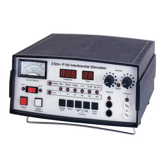
Part 1 AMREX Overview The layout of the IF150 panel consists of an analog meter, controls, indicator lights, digital displays and output jacks. IF150 User's Guide... - Page 10 Part 1 In the illustration below, dashed lines surround each of the IF150's sections. A brief description of each section follows the illustration, and Parts 2 and 3 of this manual contain detailed descriptions. IF150 User's Guide...
- Page 11 Overview Power /Timer Section Use Power/Timer Section to activate the main ac power, set the treatment duration and activate the timer. When the treatment is complete, the generator will emit an audible signal and the Intensity Reset indicator light will flash. Quad-Polar Interferential Modality Section Select the beat frequency, set the intensities and monitor the output of the Quad- Polar Interferential mode with the controls, digital displays and...
- Page 12 Part 1 IF150 User's Guide...
-
Page 13: Power/Timer Section
Part 2 AMREX Power/Timer Section In the illustration below, dashed lines surround the IF150's power/timer section. IF150 User's Guide... - Page 14 Part 2 The power/timer section of the IF150 panel is depicted below. Items referenced with circled numbers (1 – 5) are explained on the following page. IF150 User's Guide...
- Page 15 Power/Timer Section 1. POWER CONTROL: Controls the main ac power. When the power is turned on, an audible signal will be emitted and the generator will default to factory settings. If the Intensity controls are not rotated counterclockwise enabling the audible "clicks", the generator will emit a series of audible signals and the Intensity Reset indicator light will flash.
- Page 16 Part 2 IF150 User's Guide...
-
Page 17: Quad-Polar Interferential Modality
Part 3 AMREX Quad-Polar Interferential Modality In the illustration below, dashed lines surround the IF150's Quad-Polar Interferential section. IF150 User's Guide... - Page 18 Part 3 The Quad-Polar Interferential section of the IF150 panel is depicted below. Items referenced with circled numbers (6 – 10) are explained on the following page. IF150 User's Guide...
- Page 19 Quad-Polar Interferential Modality 6. SWEEP MODE AND CONTINUOUS MODE INDICATOR LIGHTS 7. SWEEP CONTINUOUS CONTROL: Selects a Sweep or Continuous mode. The Sweep mode provides a preset beat frequency range and the Continuous mode provides a preset beat frequency. The indicator light for the selected mode will illuminate.
- Page 20 Part 3 The Quad-Polar Interferential section of the IF150 panel is depicted below. Items referenced with circled numbers (11 – 18) are explained on the following page. IF150 User's Guide...
- Page 21 Quad-Polar Interferential Modality 11. CURRENT MONITOR CHANNEL SELECTION CONTROL: Selects the display of output current for Channel 1 or Channel 2. 12. CURRENT MONITOR INDICATOR LIGHT - CHANNEL 1: Indicates Channel 1 is selected for the Current Monitor. 13. CURRENT MONITOR - CHANNEL 1 and CHANNEL 2: Analog display of output current for Channel 1 or Channel 2.
- Page 22 Part 3 The Quad-Polar Interferential section of the IF150 panel is depicted below. Items referenced with circled numbers (19 – 22) are explained on the following page. IF150 User's Guide...
- Page 23 Quad-Polar Interferential Modality 19. STIMULATOR OUTPUT JACKS - CHANNEL 2: The stimulator output jacks for Channel 2 are white. 20. INTENSITY RESET INDICATOR LIGHT: The Intensity Reset indicator light will flash and an audible signal will be emitted from the generator in the event that: •...
- Page 24 Part 3 IF150 User's Guide...
-
Page 25: If150 General Operation And Application Procedures
Part 4 AMREX IF150 General Operation and Application Procedures General Operation of Quad-Polar Interferential Modality 1. Connect the IF150's ac power cord to the IF150's ac receptacle and plug the "Hospital Grade" connector to a properly grounded 120Vac, 60Hz receptacle. - Page 26 Part 4 5. Press the Select control to the desired Sweep beat frequency range or Continuous beat frequency. The selected beat frequency indicator light will illuminate and the Frequency display will indicate the selection. Note: The Sweep beat frequency range or the Continuous beat frequency can be changed anytime during treatment.
- Page 27 IF150 General Operation and Application Procedures 14. When treatment is completed, stimulator output will be discontinued immediately. • The output intensities reduce to 0 as indicated on the Current Monitor for Channel 1 and Channel 2. • The treatment time reduces to 00 as indicated on the Time display. •...
-
Page 28: Application Of Electrical Muscle Stimulation Quad-Polar
Apply a generous amount of Flextrode Conductive Spray to the moistened sponge cover. If the Flextrode Conductive Spray is not desired, apply a generous amount of Amrex Conductance and Coupling Gel to the thoroughly moistened Flextrode sponge cover. A generous amount of Flextrode Conductive Spray or Amrex Conductance and Coupling Gel is required to insure good conductivity. -
Page 29: Interferential Burns
IF150 General Operation and Application Procedures Interferential Burns With the use of interferential current, there has been a growing awareness of so called interferential “burns”. Interferential current is symmetrically biphasic; it does not produce a chemical build up in tissue. Therefore, the so called interferential “burns”... -
Page 30: Adverse Effects - Shortwave Diathermy Interference
Part 4 Adverse Effects - Shortwave Diathermy Interference It is extremely important for the physiotherapist to have a clear understanding of the potential danger involved in the use of an interferential device in close proximity to an active shortwave diathermy unit. A medical shortwave diathermy unit is a very powerful transmitter of radio energy, the larger ones having an output of 500 watts. -
Page 31: Electrical Muscle Stimulation-Indications
IF150 General Operation and Application Procedures Electrical Muscle Stimulation—Indications Relaxation of muscle spasms Prevention or retardation of disuse atrophy Increased local blood circulation Muscle reeducation Maintenance of or increase in range of motion Immediate postsurgical stimulation of calf muscles to prevent venous thrombosis Electrical Muscle Stimulators should only be used under medical supervision for adjunctive therapy for the treatment of medical diseases and conditions. -
Page 32: Electrical Muscle Stimulation-Precautions
Part 4 Electrical Muscle Stimulation—Precautions Precautions should be observed: When there is a tendency to hemorrhage following acute trauma or fracture. Following recent surgical procedures when muscle contraction may disrupt the healing process. Over the menstruating uterus. Where sensory nerve damage is present by a loss of normal skin sensation. Some patients may experience skin irritation or hypersensitivity due to the electrical stimulation or the conductive medium. -
Page 33: Specifications
Appendix A Specifications Input Power Requirements Instrument Line Voltage ......120 Vac, 60 Hz Overall Dimensions ..... 12" W x 11¾" D (Special voltages available on request) x 6" H Current ............1.0 A Overall Dimensions with tilt- up bar extended .... - Page 34 To maintain original design specifications, your Amrex stimulator must be calibrated and safety tested on an annual basis. Amrex strongly recommends that servicing be referred to the factory. Call toll free (800) 221-9069.
-
Page 35: Appendix B References
Appendix B References Andersson, S.A. "Pain Control by Sensory Stimulation". Bonica, J.J. et al ed. "Ad- vances in Pain Research and Therapy", Vol. 3, pp. 569-585. Raven Press, New York, 1979. Cauthen, J.C., and E. J. Renner. "Transcutaneous and Pheripheral Nerve Stimula- tion for Chronic Pain States". - Page 36 Appendix B IF150 User's Guide...
Need help?
Do you have a question about the Z-STIM IF150 Series and is the answer not in the manual?
Questions and answers