Table of Contents
Advertisement
Quick Links
Advertisement
Table of Contents

Subscribe to Our Youtube Channel
Related Manuals for Amrex SynchroSonic U/50


Summary of Contents for Amrex SynchroSonic U/50
- Page 1 ® electrotherapy equipment a division of Amrex-Zetron, Inc. *Federal law (USA) restricts this device to sale by or on the order of a licensed practitioner licensed by the law of the state in which he practices to use or order the use of this device.
- Page 2 SynchroSonic U/50 User's Guide Revised February 2014 Copyright © Amrex-Zetron, Inc. 1995. All rights reserved. Printed in the United States of America The following are registered or trademarked by Amrex: Amrex ® SynchroSonic ® QuickConnect ™ Flextrode ® AMREX electrotherapy equipment ®...
- Page 3 Thank you. . . for selecting the Amrex SynchroSonic U/50. We believe that you will find this instrument to be versatile, dependable and user friendly. The SynchroSonic U/50 provides the widely used therapeutic modality of ultrasound. The ultrasound may be applied separately or may be combined with electrical stimulation simultaneously through the ultrasound transducer using an external electrical stimulator.
- Page 4 Call toll free (800) 221-9069. Save the original shipping carton and all packing materials to safely return Amrex equipment to the factory for service; repair; annual calibration, electrical and mechanical safety check. All accessories, including the ac line cord, must be included with the returned instrument.
- Page 5 Important OPTIONAL FEATURE (1.0/3.3) AMREX Ultrasound Intensity Reset Circuit: The Ultrasound modality incorporates a unique reset circuit feature as a part of the intensity control. ultrasound output will be disabled in the event that: •...
- Page 6 Electrical Muscle Stimulation—Contraindications • Contraindicated for patients with cardiac demand pacemakers • Should not be used on cancer patients Electrical Muscle Stimulation—Warnings • Long term effects of chronic electrical stimulation are unknown • Safety has not been established for the use of electrical muscle stimulation during pregnancy •...
-
Page 7: Table Of Contents
Table of Contents Part 1 Overview ..........................1 Part 2 Power Section ......................... 5 Part 3 Ultrasound Modality ......................9 Part 4 U/50 General Operation and Application Procedures ........... 17 General Operation ........................17 Application of Ultrasound ....................... 19 Adverse Effects - Shortwave Diathermy Interference ............20 Ultrasound—Indications ...................... -
Page 9: Part 1 Overview
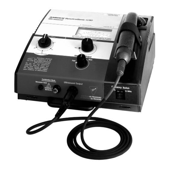
Part 1 AMREX Overview The layout of the U/50 panel is logically arranged into two major sections. These sections are, from left to right: Power and Ultrasound. U/50 User's Guide... - Page 10 Part 1 In the illustration below, dashed lines surround each of the U/50's sections. A brief description of each section follows the illustration. Parts 2 and 3 of this manual contain detailed descriptions of each section. U/50 User's Guide...
- Page 11 Overview Power Section Use the Power Section to activate the main ac power and set the treatment duration. The power will shut off and a bell will sound when the treatment is complete. Ultrasound Modality Section Set the intensity and monitor the output of ultrasonic energy with the controls, connectors and meter dial in this section of the panel.
- Page 12 Part 1 U/50 User's Guide...
-
Page 13: Power Section
Part 2 AMREX Power Section In the illustration below, dashed lines surround the U/50's power section. U/50 User's Guide... - Page 14 Part 2 The power section of the U/50 panel is depicted below. The item referenced with circled number (1) is explained on the following page. U/50 User's Guide...
- Page 15 Power Section 1. POWER/TIMER: Controls the main ac power as well as the timer for treatment. Rotate the Power / Timer knob clockwise past the 10-minute mark and then set it to the desired treatment duration. The Ultrasound On indicator light (located above the upper left corner of the Ultrasound meter) will illuminate.
- Page 16 Part 2 U/50 User's Guide...
-
Page 17: Ultrasound Modality
Part 3 A M R E X Ultrasound Modality In the illustration below, dashed lines surround the U/50's ultrasound section. U/50 User's Guide... - Page 18 Part 3 The ultrasound section of the U/50 panel is depicted below. Items referenced with circled numbers (2 – 8) are explained on the following page. U/50 User's Guide...
- Page 19 Ultrasound Modality 2. ULTRASOUND METER: Consists of four scales: Average Power Watts Refers to the total watts applied to the patient. Has a range of 0 to 20 watts. Average Intensity Watts/CM² Refers to the power density or watts per square centimeter. Has a range of 0 to 5 watts/cm².
- Page 20 Part 3 The ultrasound section of the U/50 panel is depicted below. Items referenced with circled numbers (9 – 12) are explained on the following page. U/50 User's Guide...
- Page 21 On indicator light will turn off and the ultrasound output will be non-interrupted. 10. ULTRASOUND OUTPUT TRANSDUCER CONNECTOR: Provides for connection to an Amrex ultrasound transducer. The Transducer Cable Fault Alarm System detects improper transducer cable connection and/or transducer cable damage. If a transducer cable is improperly connected or damaged, an audible signal will be emitted from the generator, the Interrupt On light will illuminate and the Ultrasound meter will display "0"...
- Page 22 Part 3 The ultrasound section of the U/50 panel is depicted below. Items referenced with circled numbers (13 – 15) are explained on the following page. U/50 User's Guide...
- Page 23 Ultrasound Modality 13. OPTIONAL FEATURE (1.0/3.3) ULTRASOUND FREQUENCY 3.3 MHz INDICATOR LIGHT: The yellow indicator light, located on the upper right corner of the Ultrasound Frequency switch bezel, will illuminate during treatment when the Ultrasound Frequency switch is in the right (3.3 MHz) position. 14.
- Page 24 Part 3 U/50 User's Guide...
-
Page 25: U/50 General Operation And Application Procedures
"click". 5. Prepare a contact medium at and around the treatment site with a liberal coating of Amrex Conductance and Coupling Gel. 6. Rotate the Power / Timer knob and set it to the desired treatment duration. Note: When the desired treatment duration is less than ten (10) minutes, rotate the Power / Timer knob clockwise past the ten- minute mark and then set it to the desired treatment duration. - Page 26 Part 4 8. Optional Feature (1.0/3.3) Set the Ultrasound Frequency switch to the desired ultrasound output frequency. Note: When the Ultrasound Frequency switch is in the left (1.0 MHz) position, the green Ultrasound Frequency indicator light, located on the upper left corner of the Ultrasound Frequency switch bezel, will illuminate and ultrasound output frequency of 1 MHz is selected.
-
Page 27: Application Of Ultrasound
Since ultrasonic energy will not be efficiently transmitted through air, a conducting medium (water or gel) must be used between the transducer and skin tissue. Amrex Conductance and Coupling Gel is recommended. This gel is excellent for ultrasonic energy transmission as well as conductance for application of electrical muscle stimulation. -
Page 28: Adverse Effects - Shortwave Diathermy Interference
Part 4 Adverse Effects - Shortwave Diathermy Interference It is extremely important for the physiotherapist to have a clear understanding of the potential danger involved in the use of a ultrasound device in close proximity to an active shortwave diathermy unit. A medical shortwave diathermy unit is a very powerful transmitter of radio energy, the larger ones having an output of 500 watts. -
Page 29: Ultrasound-Indications
U/50 General Operation and Application Procedures Ultrasound—Indications Ultrasound delivered to the body using an efficient coupling provides deep heating effects to body tissues. When therapeutic ultrasound is delivered to the body at intensities capable of generating a deep tissue temperature increase, some or all of the following effects may occur: •... -
Page 30: Ultrasound-Contraindications
Part 4 Ultrasound—Contraindications Ultrasound should not be used in the following areas: transcerebrally; near the heart or reproductive organs; over viscera, eyes, ears, the spinal column, malignancies, the joint capsule in arthritic conditions either acute or subacute, or over total joint replacements. Ultrasound should not be used in cases of: cardiac pacemakers, pregnancy, implants, malignant or benign tumors, multiple sclerosis, arteriosclerosis or weakened blood vessels, hemophilia, thrombosis and thrombophlebitis either acute or subacute. -
Page 31: The Ultrasound Transducer
For Amrex models equipped with the Amrex "QuickConnect System" and less than one (1) year since the last ultrasound calibration: The transducer cable may be replaced on site. -
Page 32: Quickconnect Transducer Cable System (Optional Feature)
Service at (800) 221-9069 and refer to Amrex part number P27-DCA. To upgrade your unit to include the “QuickConnect System,” send the transducer and the generator with your request for Amrex part number P2-RETRO, to Amrex, 641 East Walnut Street, Carson, California 90746. -
Page 33: Dual Transducers (Optional Feature)
FACTORY EQUIPPED with two assigned transducers. To change from one assigned Amrex transducer to another: 1. Verify that the Power/Timer knob is at the Off position. 2. Reduce the Ultrasound Intensity control to "0" position and thoroughly clean the transducer faceplate before placing the transducer in the transducer cradle. -
Page 34: U/50 Combination Mode
Part 4 U/50 Combination Mode The Ultrasound modality may be combined with an Electrical Stimulator for simultaneous application through the ultrasound transducer. This technique involves using a large electrode pad and the ultrasound transducer. The transducer soundhead will become the active electrode which will transmit both ultrasound and electrical stimulation. - Page 35 Slow position. 9. Prepare a contact medium at and around the treatment sites with a liberal coating of Amrex Conductance and Coupling Gel. Properly secure the thoroughly moistened dispersive pad insuring that the entire conductive area of the pad makes full contact.
- Page 36 Part 4 15. Optional Feature (1.0/3.3) Set the Ultrasound Frequency switch to the desired ultrasound output frequency. Note: When the Ultrasound Frequency switch is in the left (1.0 MHz) position, the green Ultrasound Frequency indicator light, located on the upper left corner of the Ultrasound Frequency switch bezel, will illuminate and ultrasound output frequency of 1 MHz is selected.
-
Page 37: Application Of Electrical Muscle Stimulation
Amrex Conductance and Coupling Gel to the thoroughly moistened Flextrode cloth cover. Note: A generous amount of Flextrode Conductive Spray or Amrex Conductance and Coupling Gel is required to insure good conductivity. Upon completion of treatment, remove and discard the used Flextrode cloth cover(s). -
Page 38: Adverse Effects - Shortwave Diathermy Interference
Part 4 Important Should the patient complain of low stimulation output, no output or sudden irregular increases in output, immediately discontinue treatment. Check for the following: secure cord connections; proper electrode contact with the patient; electrode wear or lack of cleanliness. Replace patient cords and/or pad electrodes that show any evidence of deterioration. -
Page 39: Electrical Muscle Stimulation-Indications
U/50 General Operation and Application Procedures Electrical Muscle Stimulation—Indications • Relaxation of muscle spasms • Prevention or retardation of disuse atrophy • Increased local blood circulation • Muscle reeducation • Maintenance of or increase in range of motion • Immediate postsurgical stimulation of calf muscles to prevent venous thrombosis Electrical Muscle Stimulators should only be used under medical supervision for adjunctive therapy for the treatment of medical diseases and conditions. -
Page 40: Electrical Muscle Stimulation-Precautions
Part 4 Electrical Muscle Stimulation—Precautions Precautions should be observed: • When there is a tendency to hemorrhage following acute trauma or fracture • Following recent surgical procedures when muscle contraction may disrupt the healing process • Over the menstruating uterus •... -
Page 41: Appendix A Specifications
(Complies with FDA Regulation 21 CFR Label Abbreviations 1050.10 and FCC Regulations) Mod .......... Model Number Frequency ........1.0 MHz ± 5% Gen ......... Generator, all Amrex optional feature 1.0/3.3 MHz ± 5% Ultrasound Models Waveform ....amplitude modulated F ............Frequency at 120 Hz ±... - Page 42 (800) 221-9069. Damage, resulting from repairs made outside the factory, is not covered under the warranty. Your Amrex stimulator must be tested and calibrated on an annual basis to maintain original design specifications. Amrex strongly recommends that servicing be referred to the factory.
-
Page 43: Appendix B References
Appendix B References Alon, G. High Voltage Stimulation (High Voltage Pulsating Direct Current). Chattanooga Corporation, Chattanooga, Tennessee, 1984. Currier, D.P. and R.M. Nelson. Clinical Electrotherapy. Appleton and Lange, Norwalk, Connecticut, 1986. Dyson, M. “Mechanisms Involved in Therapeutic Ultrasound”. Physiotherapy, March, Vol.73.3, pp.116-120, 1987. Jaskoviak, P.A. - Page 44 Appendix B U/50 User's Guide...
Need help?
Do you have a question about the SynchroSonic U/50 and is the answer not in the manual?
Questions and answers