Table of Contents
Advertisement
Quick Links
Advertisement
Table of Contents

Related Manuals for PR electronics 2231


Summary of Contents for PR electronics 2231
- Page 1 PERFORMANCE MADE SMARTER Product manual 2231 Trip amplifier T E M P E R AT U R E I . S . I N T E R FA C E S CO M M U N I C AT I O N I N T E R FA C E S...
- Page 2 6 Product Pillars to meet your every need Individually outstanding, unrivalled in combination With our innovative, patented technologies, we make signal conditioning smarter and simpler. Our portfolio is composed of six product areas, where we offer a wide range of analog and digital devices covering over a thousand applications in industrial and factory automation.
-
Page 3: Table Of Contents
Trip amplifier 2231 Table of contents Warning .................... -
Page 4: Warning
General mounting, wire connection and disconnection. VOLTAGE Troubleshooting the device. Repair of the device and replacement of circuit breakers must be done by PR electronics A/S only. Warning To keep the safety distances, devices with two built-in relays must not be connected to both hazardous and non-hazardous voltages on the same device’s relay contacts. -
Page 5: Safety Instructions
Should there be any doubt as to the correct handling of the device, please contact your local distributor or, alternatively, PR electronics A/S www.prelectronics.com Mounting and connection of the device should comply with national legislation for mounting of electric materials, i.e. wire cross section, protective fuse, and location. -
Page 6: How To Dismantle System 2200
How to dismantle system 2200 Picture 1: The back panel of the module is detached from the housing by way of a screwdriver. Picture 2: After this, the back panel can be pulled out together with the PCB, but please notice the position of the PCB as there is a number of different positions in the house. -
Page 7: Application
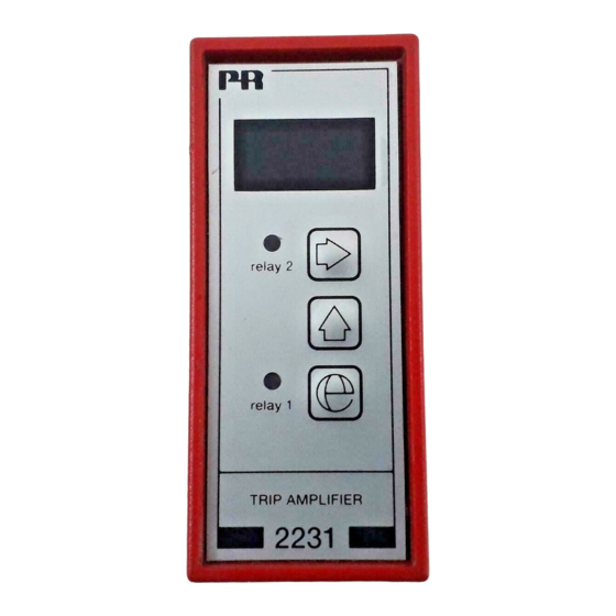
Trip amplifier 2231 • AC/DC trip amplifier • 2 adjustable alarm limits • Galvanically isolated 3.75 kVAC • Front programmable • 3-digit LED display • 24 VDC or universal supply Application Alarm detector in connection with measurement of AC/DC current or voltage signals. The unit is used where accurate setpoint setting and different alarm functions are required. -
Page 8: Electrical Specifications
Weight 2231 D / 2231 P ....... - Page 9 AC voltage input Measurement range ........0...250 VRMS Min.
-
Page 10: Order
Order Type Supply 2231 24 VDC 24...230 VAC & 24...250 VDC Block diagram Supply (+), (P) 24…230 VAC, 24...250 VDC Supply (gnd), (N) Rel. 1 common Rel. 1 JP 2 N.O. AC shunt Rel. 1 N.O. / N.C. 1 Ohm / 2 W N.C. -
Page 11: Hardware Programming
Hardware programming Input: Input 0...20 mADC 0...1 ARMS 0...250 VDC 0...250 VRMS Output: Relay JP position Relay 1 normally open JP 2 N.O. Relay 1 normally closed JP 2 N.C. Relay 2 normally open JP 3 N.O. Relay 2 normally closed JP 3 N.C. -
Page 12: Routing Diagram
Routing diagram Programming If no buttons are pressed for a period of 2 minutes, display returns to stage 0.0 Memory Fast Setting 4.2 EFS/dFS - enable / disable fast setting Downcount setpoint Go to entry menu / Leave Upcount setpoint menu without changes Next digit or point Store and exit fast setting... -
Page 13: Programming / Operating The Function Keys
Programming / operating the function keys Documentation for routing diagram The programming is menu-controlled. The main menus are numbered in level 0 (x.0), and the submenus are numbered in level 1 (x.1 to x.5). Each submenu has an accompanying entry menu. The menus are structured in such a way that the menus most frequently used are closer to the default menu 0.0. - Page 14 Begin by selecting the function for the device in menu 4.1 1.0 rE1 - Setting of parameters for relay 1 1.1 SEt / SPL - Setting of relay 1 setpoint Possible selections are 0...99.9%. The setpoint is set in % of the input signal. When the selected func tion in menu 4.1 = {004 = Setpoint window}, the low window value SPL is set in this menu.
-
Page 15: Description Of Functions (Selection Of Application)
2.4 dEL - Setting of relay 2 time delay Possible selections are 0...99.9 s. The time delay is the period in which the input value must be present before the relay switches state. 2.5 HyS - Setting of hysteresis for setpoint window Possible selections are 0...99.9%. - Page 16 004 = Setpoint window: Dual trip amplifier with setpoint window on both relays acc. to your choice. The setpoint window is set with a low and an upper value on the input signal thus making the relays active / inactive within the range. In submenus 1.1 / 2.1 the low percentage value of the input signal is set, and in submenus 1.2 / 2.2 the high percentage value of the input signal is set.
-
Page 17: Document History
Document history The following list provides notes concerning revisions of this document. Rev. ID Date Notes 2232 Relay data updated, graph with resistive loads inserted. UKCA added. 2231V105-UK... - Page 18 We are near you, all over the world Our trusted red boxes are supported wherever you are All our devices are backed by expert service and a 5-year business with a global reach. This means that we are warranty. With each product you purchase, you receive always nearby and know your local markets well.
- Page 19 Benefit today from PERFORMANCE MADE SMARTER PR electronics is the leading technology company specialized in making industrial process control safer, more reliable and more efficient. Since 1974, we have been dedicated to perfecting our core competence of innovating high precision technology with low power consumption.
Need help?
Do you have a question about the 2231 and is the answer not in the manual?
Questions and answers