
Related Manuals for PR electronics 2231


Summary of Contents for PR electronics 2231
- Page 1 2 2 3 1 T r i p a m p l i f i e r N o . 2 2 3 1 V 1 0 4 - U K S e r i a l n o . 9 8 0 1 7 0 3 0 4 - 1 9 1 0 5 7 0 0 0...
- Page 2 Vores motto »Signals the Best« er indbegrebet af denne filosofi – og din garanti for kvalitet. PR electronics A/S offers a wide range of analog and digital signal conditioning devices for industrial automation. The product range includes Isolators, Displays, Ex Interfaces, Temperature Transmitters, and Multifunctional Devices.
-
Page 3: Table Of Contents
Input ......................Functions ....................Programming .................... Display ......................Electrical specifications................ Order: 2231 ....................10 Block diagram ................... 10 Hardware programming ................ 11 Routing diagram ..................12 Programming / operation the function keys ....... 14 Description of functions (selection of application)....18... -
Page 4: Warning
General mounting, connection and disconnection of wires. Troubleshooting the device. Repair of the device and replacement of circuit breakers must be done by PR electronics A/S only. WARNING To keep the safety distances, devices with two built-in relays must not be connected to both hazardous and non-hazardous voltages on the same device’s relay contacts. -
Page 5: Symbol Identification
Should there be any doubt as to the correct handling of the device, please contact your local distributor or, alternatively, PR electronics A/S www.prelectronics.com 2231V104-UK... - Page 6 When disconnected, the device may be cleaned with a cloth moistened with distilled water. LIABILITY To the extent the instructions in this manual are not strictly observed, the custom- er cannot advance a demand against PR electronics A/S that would otherwise exist according to the concluded sales agreement. 2231V104-UK...
- Page 7 HOW TO DISMANTLE SYSTEM 2200 Picture 1: The back panel of the device is detached from the housing by way of a screw- driver. Picture 2: After this, the back panel can be pulled out together with the PCB, but please notice the position of the PCB as there is a number of different positions in the house.
-
Page 8: Technical Characteristics
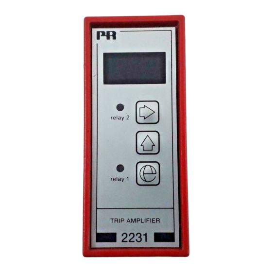
TRIP AMPLIFIER 2231 • AC/DC trip amplifier • 2 adjustable alarm limits • Galvanically isolated 3.75 kVAC • Front programmable • 3-digit LED display • 24 VDC or universal supply Applications Alarm detector in connection with measurement of AC/DC current or voltage signals. -
Page 9: Functions
Functions The front-operated push buttons are used for programming of the different standard functions. Single or dual trip amplifier can be selected. Dual trip amplifier with relay 2 as pre-setpoint, single or dual trip amplifier with hysteresis in each relay, which is set as setlow or sethigh and dual trip amplifier with hold on relay 2 until relay 1 is activated. -
Page 10: Electrical Specifications
Humidity ..............< 95% RH (non-cond.) Dimensions (HxWxD) ..........84.5 x 35.5 x 80.5 mm (excl. pins) Protection degree ............ IP50 Weight 2231 D / 2231 P ........125 g / 175 g Vibration ..............IEC 60068-2-6 : 2007 2...13.2 Hz .............. ±1 mm 13.2...100 Hz ............ - Page 11 AC current input: Measurement range ..........0...1 ARMS Min. measurement range (span) ......0.5 ARMS Max. offset ..............50% of selected max. value Input resistance............1 Ω / 2 W Updating time ............100 ms Voltage input: DC voltage input: Measurement range ..........
-
Page 12: Order: 2231
Order: 2231 Type Supply 2231 24 VDC 24...230 VAC & 24...250 VDC BLOCK DIAGRAM Supply (+), (P) 24…230 VAC, 24...250 VDC Supply (gnd), (N) Rel. 1 common Rel. 1 JP 2 N.O. AC shunt Rel. 1 N.O. / N.C. 1 Ohm / 2 W N.C. -
Page 13: Hardware Programming
HARDWARE PROGRAMMING Input: Input 0...20 mADC 0...1 ARMS 0...250 VDC 0...250 VRMS Output: Relay JP position Relay 1 normally open JP 2 N.O. Relay 1 normally closed JP 2 N.C. Relay 2 normally open JP 3 N.O. Relay 2 normally closed JP 3 N.C. - Page 14 2231V104-UK...
- Page 15 2231V104-UK...
-
Page 16: Routing Diagram
PROGRAMMING / OPERATION THE FUNCTION KEYS DOCUMENTATION FOR ROUTING DIAGRAM General The programming is menu-controlled. The main menus are numbered in level 0 (x.0), and the submenus are numbered in level 1 (x.1 to x.5). Each submenu has an accompanying entry menu. The menus are structured in such a way that the menus most frequently used are closer to the default menu 0.0. - Page 17 When menu 4.2 has been selected, EFS - Enable Fast SETTING, fast setpoint change is possible by activating the Fast Setting function. In this menu, the function keys have a special feature as 1 increases the setpoint and 3 decreases the setpoint from the value it had when activated. Activating for more than 2 s automatically activates the increment / decrement function.
- Page 18 1.3 InC / dEC - Setting of active relay 1 for increasing / decreasing input signal Possible selections are InC or dEC. If InC is selected, relay 1 will be activated when the input value is high er than the setpoint and deactivated again, when the input value is lower than the setpoint minus the hysteresis.
- Page 19 2.2 HYS / SPH - Setting of relay 2 hysteresis Possible selections are 0...99.9%. The hysteresis is set in % of the input signal. The hysteresis is the difference between the setpoint and reset values.When the selected function in menu 4.1 = {004 = Setpoint window}, the upper window value SPH is set in this menu.
-
Page 20: Description Of Functions (Selection Of Application)
3.0 Aln - SETTING OF SIGNAL INPUT 3.1 U / I - Display of input type There are two alternative displays when setting JP1 on the PCB, U and I. The input type is detected by JP1. When JP1 is installed in “I”, “I” will be displayed, and the input signal range is set in current. - Page 21 001 = Single setpoint: Single trip amplifier set in main menu 1.0 with setpoint within the range 0...99.9% of the input signal. The hysteresis is set in the range 0...99.9% of the input signal. The parameter selection determines whether the trip amplifier should be active for increasing (InC) or decreasing (dEC) input signal.
- Page 22 In submenus 1.3 / 2.3 InC increasing / dEC decreasing, the relay func tion is determined within the setpoint window. If InC is selected, the relays are active; if dEC is selected, the relays are inactive. The time delay is set in the range 0...99.9 s.
- Page 23 Displays Programmable displays with a wide selection of inputs and outputs for display of temperature, volume and weight, etc. Feature linearization, scaling, and difference measurement functions for programming via PReset software. Ex interfaces Interfaces for analog and digital signals as well as HART signals between sensors / I/P converters / frequency signals and control systems in Ex zone 0, 1 &...
- Page 24 www.prelectronics.com sales-uk@prelectronics.com www.prelectronics.com sales-us@prelectronics.com www.prelectronics.cn sales-cn@prelectronics.com www.prelectronics.be sales-be@prelectronics.com Head office Denmark www.prelectronics.com PR electronics A/S sales-dk@prelectronics.com Lerbakken 10 tel. +45 86 37 26 77 DK-8410 Rønde fax +45 86 37 30 85...
Need help?
Do you have a question about the 2231 and is the answer not in the manual?
Questions and answers