Mars Comfort-Aire Century A-VMH18DV-1 Installation Manual
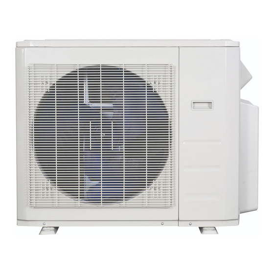
Outdoor units
Hide thumbs
Also See for Comfort-Aire Century A-VMH18DV-1:
- Installation manual (28 pages) ,
- Service manual (132 pages)

Related Manuals for Mars Comfort-Aire Century A-VMH18DV-1


Summary of Contents for Mars Comfort-Aire Century A-VMH18DV-1
- Page 1 INSTALLATION MANUAL UltraV Series Outdoor Units Models A-VMH18DV-1 A-VMH28TV-1 A-VMH36QV-1 A-VMH48PV-1 517.787.2100 • www.marsdelivers.com...
-
Page 2: Table Of Contents
Installation Manual - A-VMH18DV,28TV,36QV,48PV-1 Table of Contents Installation Manual Accessories ............ Safety Precautions ........Installation Overview ....... Installation Diagram ........ Speci cations ..........Outdoor Unit Installation ......Outdoor Unit Installation Instructions ..11 Drain Joint Installation ........ Notes on Drilling Hole in Wall .... - Page 3 Installation Manual - A-VMH18DV,28TV,36QV,48PV-1 Refrigerant Piping Connection ....Wiring ..........Outdoor Unit Wiring ....Wiring Figure ........ Air Evacuation .......... Evacuation Instructions ......Note on Adding Refrigerant ....Safety And Leakage Check ....Test Run ............Function of Automatic Wiring/Piping Correction ..
- Page 4 Installation Manual - A-VMH18D ,28T ,36Q ,48P -1 Accessories The air conditioning system comes with the following accessories. Use all of the installation parts and accessories to install the air conditioner. Improper installation may result in water leakage, electrical shock and re, or equipment failure. Name Shape Quantity...
- Page 5 Installation Manual - A-VMH18DV,28TV,36QV,48PV-1 Safety Precautions Read Safety Precautions Before Installation Incorrect installation due to ignoring instructions can cause serious damage or injury. The seriousness of potential damage or injuries is classified as either a WARNING or CAUTION. Failure to observe a warning may result in death. The appliance must be installed in accordance with national regulations.
- Page 6 Installation Manual - A-VMH18D ,28T ,36Q ,48P -1 WARNING The appliance disconnection must be incorporated with an all-pole disconnection device using • hard wiring in accordance with electrical codes. Any person who is involved with working on or breaking into a refrigerant circuit should hold a •...
- Page 7 Installation Manual - A-VMH18DV,28TV,36QV,48PV-1 Note about Fluorinated Gasses 1. This air-conditioning unit contains fluorinated gasses. For specific information on the type of gas and the amount, please refer to the relevant label on the unit itself. 2. Installation, service, maintenance and repair of this unit must be performed by a certified technician. 3.
- Page 8 Installation Manual - A-VMH18DV,28TV,36QV,48PV-1 Installation Overview INSTALLATION ORDER Install the outdoor unit Connect the refrigerant pipes Connect the wires (Page 11) (Page 14) (Page 17) Evacuate the refrigeration Perform a test run (Page 26) system (Page 23)
- Page 9 Installation Manual - A-VMH18DV,28TV,36QV,48PV-1 Remote controller holder Installation Diagram Installation Diagram Minimum - 3" Refer to the following diagram to ensure Air-break Installation plate proper distance from walls and ceiling: Switch Clip anchor M M i i n n i i m m u u m m c c l l e e a a r r a a n n c c e e - - 3 3 " " Air-break Switch 0"...
- Page 10 Installation Manual - A-VMH18D ,28T ,36Q ,48P -1 Specifications Table 5.1 Number of units that can be used Connected units 1-4 units together Compressor stop/start frequency Stop time 3 min or more voltage uctuation within ±10% of rated voltage Power source voltage voltage drop during start within ±15% of rated voltage interval unbalance...
-
Page 11: Outdoor Unit Installation
Installation Manual - A-VMH18DV,28TV,36QV,48PV-1 Outdoor Unit Installation The area must be free of combustible gases √ Outdoor Unit Installation Instructions and chemicals. √ The pipe length between the outdoor and Step 1: Select installation location. indoor unit may not exceed the maximum The outdoor unit should be installed in a allowable pipe length. - Page 12 Installation Manual - A-VMH18D ,28T ,36Q ,48P -1 Split Type Outdoor Unit Table 6.1: Length Specifications of Split Type (Refer to Fig 6.4, 6.5, 6.6, 6.10 and Table 6.1) Outdoor Unit (unit: mm/inch) Outdoor Unit Dimensions Mounting Dimensions W x H x D Distance A Distance B 760x590x285 (29.9x23.2x11.2)
-
Page 13: Drain Joint Installation
Installation Manual - A-VMH18DV,28TV,36QV,48PV-1 NOTE: The minimum distance between the Notes On Drilling Hole In Wall outdoor unit and walls described in the You must drill a hole in the wall for the installation guide does not apply to airtight refrigerant piping, and the signal cable that will rooms. -
Page 14: Refrigerant Piping Connection
Installation Manual - A-VMH18DV,28TV,36QV,48PV-1 Refrigerant Piping Connection Step1: Cut pipes Safety Precautions When preparing refrigerant pipes, take extra care to cut and flare them properly. This will WARNING ensure efficient operation and minimize the • All eld piping must be completed by a need for future maintenance. - Page 15 Installation Manual - A-VMH18DV,28TV,36QV,48PV-1 Pipe Table 7.1: PIPING EXTENSION BEYOND FLARE FORM Reamer Pipe Tightening Flare dimension (A) Flare shape torque (Unit: mm/Inch) gauge Point down Min. Max. 18-20 N.m 90 ° ± 4 1/4" 8.4/0.33 8.7/0.34 (183-204 kgf.cm) 25-26 N.m 3/8"...
- Page 16 Installation Manual - A-VMH18DV,28TV,36QV,48PV-1 7. Thread this pipeline through the wall and NOTE: Use both a spanner and a torque wrench connect it to the outdoor unit. when connecting or disconnecting pipes to/from 8. Insulate all the piping, including the valves the unit.
-
Page 17: Wiring
Installation Manual - A-VMH18DV,28TV,36QV,48PV-1 Wiring Follow these instructions to prevent distortion Safety Precautions when the compressor starts: WARNING • The unit must be connected to the main outlet. Normally, the power supply must • Be sure to disconnect the power supply have a low output impedance of 32 ohms. - Page 18 Installation Manual - A-VMH18DV,28TV,36QV,48PV-1 b. Using wire strippers, strip the rubber jacket 3. Connect the u-lugs to the terminals from both ends of signal cable to reveal Match the wire colors/labels with the labels on the terminal block, and firmly screw the u-lug about 15cm (5.9”) of the wires inside.
-
Page 19: Wiring Figure
Installation Manual - A-VMH18DV,28TV,36QV,48PV-1 Wiring Figure CAUTION Connect the connective cables to the terminals, as identi ed, with their matching numbers on the terminal block of the indoor and outdoor units. For example, in the US models shown in the following diagram, Terminal L1(A) of the outdoor unit must connect with terminal L1 on the indoor unit. -
Page 20: L N
Installation Manual - A-VMH18DV,28TV,36QV,48PV-1 L(A) N(A) S(A) L(B) N(B) S(B) S(A) L(A) S(2) S(A) N(A) L(A) S(2) N(A) S(1) S(B) N(B) L(B) L S(1) S(B) N(B) L(B) L TO A TO B SUPPLY POWER POWER SUPPLY SUPPLY TO B TO B TO A TO A Model H... - Page 21 Installation Manual - A-VMH18DV,28TV,36QV,48PV-1 One-four models: Model A Model B Model C Model D L(A) N(A) S(A) L(B) N(B) S(B) L(C) N(C) S(C) L(D) N(D) S(D) TO A TO A TO B TO B SUPPLY Model E Model F...
- Page 22 Installation Manual - A-VMH18DV,28TV,36QV,48PV-1 CAUTION After con rmation of the above conditions, follow these guidelines when performing wiring: • Always have an individual power circuit speci cally for the air conditioner. Always follow the circuit diagram posted on the inside of the control cover. •...
-
Page 23: Air Evacuation
Installation Manual - A-VMH18DV,28TV,36QV,48PV-1 Air Evacuation NOTE: If there is no change in system pressure, Safety Precautions unscrew the cap from the packed valve (high pressure valve). If there is a change in system CAUTION pressure, there may be a gas leak. •... -
Page 24: Note On Adding Refrigerant
Installation Manual - A-VMH18DV,28TV,36QV,48PV-1 Note On Adding Refrigerant CAUTION • Refrigerant charging must be performed after wiring, vacuuming, and the leak testing. • DO NOT exceed the maximum allowable quantity of refrigerant or overcharge the system. Doing so can damage the unit or impact it’s functioning. •... -
Page 25: Safety And Leakage Check
Installation Manual - A-VMH18DV,28TV,36QV,48PV-1 Safety And Leakage Check Electrical safety check Gas leak check Perform the electrical safety check after 1. Soap water method: completing installation. Cover the following Apply a soap-water solution or a liquid areas: neutral detergent on the indoor unit 1. -
Page 26: Test Run
Installation Manual - A-VMH18DV,28TV,36QV,48PV-1 Test Run f. Check to see that the drainage system is Before Test Run unimpeded and draining smoothly. A test run must be performed after the entire g. Ensure there is no vibration or abnormal system has been completely installed. Confirm noise during operation. -
Page 27: Function Of Automatic Wiring/Piping Correction
Installation Manual - A-VMH18DV,28TV,36QV,48PV-1 Function of Automatic Wiring/Piping Correction Automatic Wiring/Piping Correction Function More recent models now feature automatic correction of wiring/piping errors. Press the "check switch" on the outdoor unit PCB board for 5 seconds until the LED displays "CE”, indicating that this function is working, Approximately 5-10 minutes after the switch is pressed, the "CE"... - Page 28 1900 Wellworth Ave., Jackson, MI 49203 • Ph. 517-787-2100 • www.marsdelivers.com 10/2022...
Need help?
Do you have a question about the Comfort-Aire Century A-VMH18DV-1 and is the answer not in the manual?
Questions and answers