
Related Manuals for frasch NET


Summary of Contents for frasch NET
- Page 1 | frasch.com | 682.200.3005 682.200.3005 : ASSEMBLY INSTRUCTIONS ACOUSTICAL BAFFLE TOOLS REQUIRED Level Pencil/Marker Tape Measure Power Drill Wire Cutters 01 of 10 rev. date 8.20.2022...
- Page 2 Standard hardware shown does not include direct to ceiling, wall or floor hardware. All customers of Fräsch products are responsible for the selection of final surface mounting hardware. Please contact support@frasch.com to review your unique site conditions and select the appropriate hardware package. 02 of 10...
-
Page 3: Included Components
| frasch.com | 682.200.3005 682.200.3005 ASSEMBLY INSTRUCTIONS INCLUDED COMPONENTS 11.75” 11.75” Fin A1 Fin A2 [x8] [x8] 11.5” 11.5” Fin B Fin B2 [x8] [x8] 10.75” 10.75” Fin C Fin C2 [x8] [x8] 10” 10” Fin D Fin D2... - Page 4 682.200.3005 ASSEMBLY INSTRUCTIONS MODULE RIB LAYOUT NET is formed by 4 identical assemblies refered to as “modules”. Once completed, the modules are hung one by one and the dovetail connector is installed at the seam of each connecting fin. Refer to this diagram when assembling the modules.
- Page 5 | 682.200.3005 : ASSEMBLY INSTRUCTIONS ASSEMBLING THE MODULE Step 2: Assemble the “2” variant fins inside the frame. Step 1: Assemble a box frame of the first module with the 4 corresponding fins as shown above. Step 3: Complete the module by assembling the remaing fins.
- Page 6 C: Ensure the cable threads through inserting the cable end. Releasing the the side opening. Use the locking mechanism to adjust the level of NET, nipple locks the cable in place then trim the excess cable D: Press the brackets firmly into the fin possitions shown in the diagram above.
- Page 7 | 682.200.3005 : INSTALLATION INSTRUCTION CEILING MOUNT LOCATION Use this diagram as a reference to install mounting harware in the ceiling. 95.00 88.50 71.25 54.00 41.00 23.75 6.50 07 of 10...
- Page 8 | 682.200.3005 : ASSEMBLY INSTRUCTION CONNECTING THE MODULES Step 4: Remove the inserts from the ends of the fins. Hang and level the first module. Step 5: Hang and level the second module. Use the bowtie connectors to join each fin at the seam.
- Page 9 | 682.200.3005 : ASSEMBLY INSTRUCTION CONNECTING THE MODULES Step 6: Connect the remaining modules. 09 of 10...
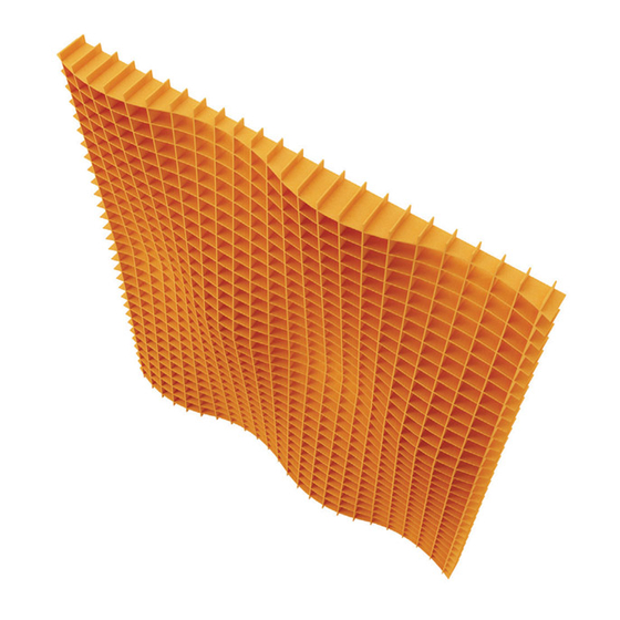
- Page 10 | 682.200.3005 : ASSEMBLY INSTRUCTION INSTALLATION COMPLETE For questions, concerns or help with installation, contact support@frasch.com 10 of 10...
Need help?
Do you have a question about the NET and is the answer not in the manual?
Questions and answers