
Related Manuals for BRUEL & KJAER 4184-A


Summary of Contents for BRUEL & KJAER 4184-A
- Page 1 Technical Documentation Weatherproof Microphone Unit Type 4184-A for Hand-held Analyzer Types 2250, 2250-L and 2270 Supplement to Instruction Manual BE 1712 English BE 1843 – 12...
- Page 3 Weatherproof Microphone Unit Type 4184-A for Hand-held Analyzer Types 2250, 2250-L and 2270 Type 2250, from Hardware Version 1.1 Type 2250-L, from Hardware Version 2.0 Type 2270, from Hardware Version 3.0 Supplement to Instruction Manual BE 1712 BE 184312 March 2012...
- Page 4 Safety Considerations This apparatus has been designed and tested in accordance with IEC 61010 – 1 and EN 61010 – 1 Safety Require- ments for Electrical Equipment for Measurement, Control and Laboratory Use. This manual contains infor- mation and warnings which must be followed to ensure safe operation and to retain the apparatus in safe condition. Special note should be made of the following: Safety Symbols The apparatus will be marked with this symbol when it is important that you refer to the associated warning...
-
Page 5: Table Of Contents
Using Microphone Type 4184-A ....................... 37 Mount Pistonphone Type 4228 onto Type 4184-A .................. 37 Mount Multifunction Acoustic Calibrator Type 4226 onto Type 4184-A........... 38 Mount Electrical Substitute for Microphones on the Built–in Microphone Preamplifier ......40 INDEX ................................... 43... -
Page 7: Chapter 1 Introduction
Weatherproof Microphone Unit Type 4184-A includes the Microphone Preamplifier Type ZE-0773 • Weatherproof Microphone Unit Type 4184-A is specified for two reference directions. In the user interface they are selected as two different microphones and are called: 4184-A 0° (Top) and 4184-A 90° (Side) –... - Page 8 Weatherproof Microphone Unit Type 4184-A – Supplement to Instruction Manual BE 1712 • Weatherproof Microphone Unit Type 4184-A cannot be mounted directly onto the analyzer. It is always connected through an extension cable • Weatherproof Microphone Unit Type 4184-A is not specified together with Outdoor Microphone Kit UA-1404 Table 1.1...
-
Page 9: Information Required By The Standards
The microphone should not be mounted outdoors with other orientations. Weatherproof Microphone Unit Type 4184-A can be mounted on a pipe with Pole Adapter DB-3068. The adapter has a female thread that fits onto the male thread of standard 1.5 opening diameter water pipes (ISO 228-1 G1). -
Page 10: Calibration
Types 2250 and 2270 BE 1713, User Manual for Hand-held Analyzer Type 2250-L BE 1766, and in appendix D.1 of this manual. Weatherproof Microphone Unit Type 4184-A should be calibrated with Brüel & Kjær Pistonphone Type 4228. Type 4228 is a class LS calibrator as specified in International Standard IEC 60942, Electro- acoustics Sound Calibrators. -
Page 11: Chapter 3 Conformance Testing
Expanded Uncertainties of Measurement. This has to be demonstrated with a good, known laboratory microphone. For Acoustical tests, Weatherproof Microphone Unit Type 4184-A should be mounted on a standard 1.5 water pipe, see section 2.2. The pipe must be of sufficient length, so as to avoid influence of reflections from the mounting of the pipe in the test rig. -
Page 12: Electrical Substitute For Microphones
The microphone cartridge is an integrated part of the weather protection in Weatherproof Microphone Unit Type 4184-A. For instructions on how to mount WA-0302-C on the preamplifier see appendix D.3. This Electrical Substitute for Microphones has, together with the preamplifier; a nominal attenuation of 0.55 dB. -
Page 13: Chapter 4 Specifications
Reference Direction: Two different reference directions of Sound Incidence: • 4184-A 0 (Top): This reference direction is defined as the inward direction toward the Microphone Reference Point on the microphones rotational axis, coming from the opposite direction of the electrical output •... - Page 14 Weatherproof Microphone Unit Type 4184-A – Supplement to Instruction Manual BE 1712 4.6.2 Typical Low-frequency Responses The typical Low-frequency Responses for Z-frequency weighting are given in Fig.4.2. The Electrical Responses are for the rear (Input) socket. The Acoustical Responses include Weatherproof Microphone Unit Type 4184-A (which again includes Microphone Preamplifier ZE-0773).
- Page 15 Specifications Fig.4.6a 4184-A 0° (Top), Free-field reference direction frequency response for Weatherproof Microphone Unit Type 4184-A and the analyzer’s electrical response with the Microphone Preamplifier connected to a microphone extension cable. Corresponds to the “Acoustical Response” column in Table A.4a...
-
Page 16: Directional Responses
1000 10000 110409 Fig.4.11 Weatherproof Microphone Unit Type 4184-A is not specified together with Outdoor Microphone Kit UA-1404 Directional Responses This section gives directional responses for plane progressive sinusoidal sound waves normalised to the response in the reference direction. The directional responses are given as tables in Appendix A. - Page 17 Corresponds to Table A.31 to Table A.33. The sound incidence angles are for 4184-A 0° (Top)’s reference direction. For 4184-A 90° (Side), subtract 90° from the angles in the plots to get the sound incidence angle 0°...
- Page 18 Weatherproof Microphone Unit Type 4184-A – Supplement to Instruction Manual BE 1712 Fig.4.18a 4184-A 0° (Top), sensitivity variations for Weatherproof Microphone Unit Type 4184-A with the Microphone Preamplifier connected to a microphone extension cable, at sound incidence angles within ±...
-
Page 19: Self-Generated Noise
CHAPTER 4 Specifications Fig.4.18b 4184-A 90° (Side), sensitivity variations for Weatherproof Microphone Unit Type 4184-A with the Microphone Preamplifier connected to a microphone extension cable, at sound incidence angles within ± ° from the reference direction. Corresponds to Table A.34b ±... - Page 20 Weatherproof Microphone Unit Type 4184-A – Supplement to Instruction Manual BE 1712 4.8.1 Maximum Broadband Self-generated Noise Table 4.1 Frequency Weighting Maximum broadband self-generated noise Z-weighting Maximum A-weighting B-weighting C-weighting Noise Z-weighting Extended Low (dB) (dB) (dB) (dB) Frequency (dB)
- Page 21 CHAPTER 4 Specifications 4.8.3 Typical Self-generated Noise Spectra Typical spectra for self-generated noise are shown in Fig.4.24 to Fig.4.29. Fig.4.24 Typical self-generated noise, 1/1 octave band, Single-range Microphone Electrical Total 30 dB 25 dB 20 dB 15 dB 10 dB 5 dB 0 dB -5 dB...
- Page 22 Weatherproof Microphone Unit Type 4184-A – Supplement to Instruction Manual BE 1712 Fig.4.26 Typical self-generated noise, 1/1 octave band, Low Range Microphone Electrical Total 30 dB 25 dB 20 dB 15 dB 10 dB 5 dB 0 dB -5 dB...
-
Page 23: Measuring Ranges
Crosstalk This only applies to Type 2270. Not relevant: only one Weatherproof Microphone Unit Type 4184-A can be connected to Type 2270. Measuring Ranges The Upper Limit in the following sections is based on the guaranteed worst-case limit for the analyzer and the nominal Open Circuit Sensitivity of the microphone. - Page 24 Weatherproof Microphone Unit Type 4184-A – Supplement to Instruction Manual BE 1712 The Lower Limit in the following sections is based on the guaranteed worst-case limit for the analyzer and the nominal Open Circuit Sensitivity of the microphone, under Reference Environmental Conditions, Sound Field Correction set to Free-field and no microphone accessories selected.
- Page 25 CHAPTER 4 Specifications 4.9.4 Indicator Range Indicator Range according to the International Standard IEC 60804: Table 4.5 Lower Limit Indicator Range Upper Z-weighting Range Limit A-weighting B-weighting C-weighting Z-weighting Extended Low (dB) (dB) (dB) (dB) (dB) Frequency (dB) Single 149.3 38.9 37.5 38.0...
- Page 26 Weatherproof Microphone Unit Type 4184-A – Supplement to Instruction Manual BE 1712 4.9.7 Linear Operating Range The starting point for all the Linear Operating Range test frequencies is 124 dB except at 31.5 Hz, which is 94.0 dB. Linear Operating Range according to the International Standard IEC 61672–1: Table 4.8...
- Page 27 CHAPTER 4 Specifications 4.9.8 Peak C Range Peak C Range according to the International Standard IEC 61672-1: Table 4.9 Lower Upper Limit Peak C Range Limit Range 31.5 Hz 1 kHz 4 kHz 8 kHz 12.5 kHz (dB) (dB) (dB) (dB) (dB) (dB)
- Page 28 Weatherproof Microphone Unit Type 4184-A – Supplement to Instruction Manual BE 1712 4.12.5 Immunity to Power Magnetic Fields Maximum sensitivity to power line (50/60 Hz) magnetic field strength of 80 A/m: is specified as the rise in the self-generated noise coming from the magnetic field. The self-generated noise is stated in section 4.8.
-
Page 29: Appendix A Tables
Weatherproof Microphone Unit Type 4184-A cannot be mounted directly on the analyzer Table A.4a 4184-A 0° (Top), Free-field reference direction frequency response for Weatherproof Microphone Unit Type 4184-A and the analyzer’s electrical response with the Microphone Preamplifier connected to a microphone extension cable Nominal... - Page 30 –10.13 0.82 –9.31 0.57 Table A.4b 4184-A 90° (Side), Free-field reference direction frequency response for Weatherproof Microphone Unit Type 4184-A and the analyzer’s electrical response, with the Microphone Preamplifier connected to a microphone extension cable Nominal Exact Microphone Electrical Acoustical...
- Page 31 –10.51 3.73 –6.78 0.57 22400 22387.2 –12.04 3.69 –8.35 0.57 Table A.5 Weatherproof Microphone Unit Type 4184-A cannot be mounted directly on the analyzer Table A.6 Weatherproof Microphone Unit Type 4184-A is not specified together with Outdoor Microphone Kit UA-1404...
-
Page 32: Diffuse-Field Frequency Responses
Weatherproof Microphone Unit Type 4184-A is not specified without windscreen Table A.8 Both reference directions, Diffuse-field frequency response for Weatherproof Microphone Unit Type 4184-A and the analyzer’s electrical response, with the Microphone Preamplifier connected to a microphone extension cable Nominal... -
Page 33: Free-Field Frequency Responses For Diffuse-Field Calibrated Instruments
–11.19 2.98 –8.21 1.04 Table A.9 Weatherproof Microphone Unit Type 4184-A is not specified together with Outdoor Microphone Kit UA-1404 Free-field Frequency Responses for Diffuse-field Calibrated Instruments Free-field frequency response in the reference direction for diffuse-field calibrated instruments according to IEC 60651 and IEC 60804. -
Page 34: Directional Responses
Weatherproof Microphone Unit Type 4184-A – Supplement to Instruction Manual BE 1712 Nominal Exact Configuration Configuration Frequency Frequency as in as in (6 digits) Table A.4a Table A.4b 1900 1883.65 0.16 –0.17 2000 1995.26 0.24 –0.17 2120 2113.49 0.23 –0.20 2240 2238.72... - Page 35 APPENDIX A Tables Table A.17 Weatherproof Microphone Unit Type 4184-A cannot be mounted directly on the analyzer Table A.18 Weatherproof Microphone Unit Type 4184-A cannot be mounted directly on the analyzer Table A.19 Weatherproof Microphone Unit Type 4184-A cannot be mounted directly on the analyzer Table A.20...
- Page 36 The sound incidence angles are for 4184-A 0° (Top)'s reference direction. For 4184-A 90° (Side) subtract 90° degrees from the angles in the table to get the sound incidence angle. 500 Hz – 3550 Hz, in dB...
- Page 37 The sound incidence angles are for 4184-A 0° (Top)'s reference direction. For 4184-A 90° (Side) subtract 90° degrees from the angles in the table to get the sound incidence angle. 4000 Hz – 10600 Hz, in dB...
- Page 38 The sound incidence angles are for 4184-A 0° (Top)'s reference direction. For 4184-A 90° (Side) subtract 90° degrees from the angels in the table to get the sound incidence angle. 11200 Hz – 20000 Hz, in dB...
- Page 39 APPENDIX A Tables Table A.34a 4184-A 0° (Top), sensitivity variations for Weatherproof Microphone Unit Type 4184-A with the Microphone Preamplifier connected to a microphone extension cable, at sound incidence angles within ± ° from the reference direction Nominal Exact...
- Page 40 Weatherproof Microphone Unit Type 4184-A – Supplement to Instruction Manual BE 1712 Table A.34b 4184-A 90° (Side), sensitivity variations for Weatherproof Microphone Unit Type 4184-A with the Microphone Preamplifier connected to a microphone extension cable, at sound incidence angles within ±...
-
Page 41: Periodic Testing Of Acoustical Frequency Responses
The uncertainty of the corrections in Table A.49 includes a component for inter-sample variability of Weatherproof Microphone Unit Type 4184-A. Due to the construction of the microphone, the inter-sample variability cannot be separated from the adjustment data. The uncertainty is allowed for in the adjustment of Weatherproof Microphone Unit Type 4184-A. - Page 42 Weatherproof Microphone Unit Type 4184-A – Supplement to Instruction Manual BE 1712...
-
Page 43: Using Microphone Type 4184-A
Using Microphone Type 4184-A Mount Pistonphone Type 4228 onto Type 4184-A Weatherproof Microphone Unit Type 4184-A should be calibrated with Brüel & Kjær Pistonphone Type 4228, which has a calibration frequency of 251.2 Hz and a calibration level of approximately 124 dB. -
Page 44: Mount Multifunction Acoustic Calibrator Type 4226 Onto Type 4184-A
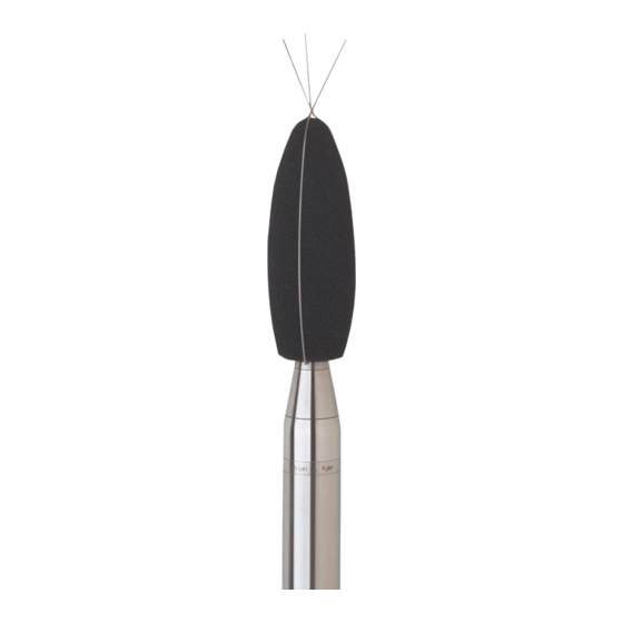
Calibration Adaptor DB-4199: NOTE: • Because the Microphone Type 4184-A is partly disassembled during this test, the test should only be performed in a clean environment • Avoid excessive torque when screwing the tip on to or off of the microphone. Approximately 2.5 cm below the probe termination there are venting holes. - Page 45 APPENDIX D Using Microphone Type 4184-A 4) Mount Calibration Adaptor DB-4199: a) Loosen the Acoustic Coupler UA-1231 tightening ring by turning it counter clockwise. b) Place Calibration Adaptor DB-4199 into the coupler. c) Re-tighten the coupler tightening ring by turning it clockwise.
-
Page 46: Mount Electrical Substitute For Microphones On The Built-In Microphone Preamplifier
Mount Electrical Substitute for Microphones on the Built–in Microphone Preamplifier NOTE: Because the Microphone Type 4184-A is partly disassembled during this test, the test should only be performed in a clean environment. To mount Electrical Substitute for Microphone Cartrigte WA-0302: 1) Unscrew the base of the Type 4184-A microphone housing using Pin Wrench QA-0178 (Fig.D.5). - Page 47 APPENDIX D Using Microphone Type 4184-A 4) Connect Electrical Substitute for Microphone cartridge WA-0302-C to the electrical assembly using Dummy Microphone Holder DB-4237 (Fig.D.8). Fig.D.8 Left: Microphone cartridge WA-0302.-C, dummy holder DB-4237 and electronics assembly Right: Optional UNF-to- BNC Adaptor...
- Page 48 Weatherproof Microphone Unit Type 4184-A – Supplement to Instruction Manual BE 1712...
-
Page 49: Index
Index Microphone Reference Point ............7 Mounting and Placing the Microphone ..........3 About This Manual ................1 Mounting for Acoustical Tests ............5 Mounting for Mechanical Vibration Tests .........5 Calibration ..................4 Cartridge Capacitance ..............7 Nominal Open Circuit Sensitivity ............7 Components Included with Type 2250/2270 ........2 Nominal Preamplifier Attenuation .............7 Conformance Testing ............... - Page 50 Weatherproof Microphone Unit Type 4184-A – Supplement to Instruction Manual BE 1712...
- Page 52 HEADQUARTERS: Brüel & Kjær Sound & Vibration Measurement A/S · DK-2850 Nærum · Denmark Telephone: +45 7741 2000 · Fax: +45 4580 1405 · www.bksv.com · info@bksv.com Local representatives and service organisations worldwide...
Need help?
Do you have a question about the 4184-A and is the answer not in the manual?
Questions and answers