Table of Contents
Advertisement
Quick Links
COMPATIBILITY
This acoustic device is only compatible with conventional control panels and systems, unless an approved optional module is fitted. For more
specific information regarding compatibility refer to your fire security system supplier and the technical documentation concerning the control
panel in use.
INSTALLATION - IMPORTANT NOTES
Refer to national and international standards in use for spacing and positioning of the fire security's system devices; refer also to specific
standards and your supplier if the system is going to be installed in particular environments or environments where specific risks exist.
This device is to be used only with conventional control panels and systems (check the COMPATIBILITY paragraph).
This device must be wired according to the connection details described in this manual.
Disconnect the sounder line from the control panel before installing this device.
Test the device after installation.
SOUNDER OPENING PROCEDURE
In order to detach the upper sounder body from the base:
1) Insert the pins of the compatible key into the holes of one of the two side locking mechanisms.
2) Turn the key 90° to the left whilst applying light pressure.
3) Repeat this step for the second side locking mechanism; the locking mechanism appears as in picture 1 when
in the open position (flush).
4) Detach the sounder body from the base by pulling gently to separate (picture 3).
SOUNDER CLOSING PROCEDURE
In order to assemble the sounder body to the base:
1) Assemble the sounder body to the base using gentle pressure (picture 3).
2) Insert the pins of the compatible key into the holes of one of the two side locking mechanisms.
3) Turn the key 90° to the right.
4) Repeat this step for the second side locking mechanism, starting from point 2; the locking mechanism ap-
pears as in picture 2 once closed (recessed).
5) To secure use the retaining screws, using the location holes on both sides of the base (picture 4).
STERLING SAFETY SYSTEMS - Unit B12a, Holly Farm Business Park, Honiley, Warwickshire,
CV81NP
HFC-SBW-23-03
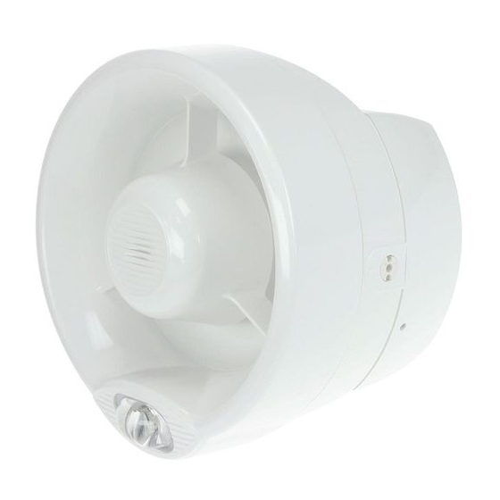
CONVENTIONAL WALL SOUNDER + VISUAL ALARM DEVICE
Picture 3
(WHITE BODY)
Picture 4
928y/01
Picture 1
Picture 2
www.sterlingsafety.co.uk
Advertisement
Table of Contents

Related Manuals for hyfire HFC-SBW-23-03


Summary of Contents for hyfire HFC-SBW-23-03
- Page 1 HFC-SBW-23-03 CONVENTIONAL WALL SOUNDER + VISUAL ALARM DEVICE (WHITE BODY) 928y/01 COMPATIBILITY This acoustic device is only compatible with conventional control panels and systems, unless an approved optional module is fitted. For more specific information regarding compatibility refer to your fire security system supplier and the technical documentation concerning the control panel in use.
- Page 2 EN 54-3 Type B - approved for outdoor use. OUTDOORS AND DAMP ENVIRONMENTS INSTALLATION When installing the sounder outdoors or in a damp environment, carefully apply the self-adhesive sealing pad to the back of the sounder base (picture 5). Picture 5 WALL INSTALLATION 1) Choose the installation location for the sounder based upon system design regulations.
- Page 3 WIRING Connect the sounder to the sounder circuit from the control panel; wiring terminal connections are as illustrated in picture 10 and described in table 1; an example of a typical circuit wiring arrangement is shown in picture 11. Picture 10 Terminal block number Terminal block designation Notes...
- Page 4 OUTPUT TONE SETTING Use the DIP switch on the back of the sounder body to select the tone required; for this function the first five switches are used, highlighted in picture 12. Picture 12 The switches positioned upwards acquire value “1”; on the other hand, if positioned downwards acquire value “0”. 1) From the MAIN TONE SET table or the ALTERNATE TONE SET table (the choice of the table depends on how the sounder’s wiring has been carried out) select the output alarm tone triggered when the sounder is activated.
- Page 5 MAIN TONE SET DIP switch Tone Tone designation Tone description configuration: number 1,2,3,4 e 5 Warble Tone 800Hz for 500ms, then 1000Hz for 500ms 11101 Continuous tone 970Hz continuous tone 01011 Slow Whoop (Dutch) 500-1200Hz for 3500ms, then off for 500ms 10101 German DIN tone 1200-500Hz swept every 1000ms (1Hz)
- Page 6 ALTERNATIVE TONE SET Tone DIP switch configuration: Tone description number 1,2,3,4 e 5 800Hz continuous 11101 1000Hz continuous tone 01011 500-1200Hz for 3500ms, then off for 500ms 10101 800Hz continuous 00111 2400Hz continuous 10010 800Hz continuous 11110 500Hz continuous 11100 500Hz continuous 10100 2400Hz continuous...
- Page 7 TESTING 1) Activate an alarm or evacuate condition at the control panel. 2) Check both the audible and visual activation of the sounder/VAD. 3) Press the SILENCE SOUNDERS button (or equivalent) and ensure all Sounder type devices have silenced before continuing. 4) Reset the system from the control panel.
- Page 8 EN 54-23:2010 by special environmental conditions. Refer to and follow national codes of practice and other internationally recognized HFC-SBW-23-03 fire engineering standards. Appropriate risk assessment should be carried out initially to determine correct For use in compatible fire detection and alarm system.
Need help?
Do you have a question about the HFC-SBW-23-03 and is the answer not in the manual?
Questions and answers