
Related Manuals for Mikro RX380


Summary of Contents for Mikro RX380
- Page 1 Digital Power Meter User Manual RX380 No.3, Jalan Anggerik Mokara 31/48, Seksyen 31, Kota Kemuning, 40460 Shah Alam, Selangor, Malaysia Website: www.itmikro.com.my Tel: +(603)5525 3863 Fax: +(603)5525 3873...
- Page 2 Mikro shall not be liable for errors contained herein including any incidental and/or consequential damages arising from the use of this material. Mikro also reserves the right to vary the product from that described in this material without prior notice.
-
Page 3: Table Of Contents
CONTENTS 1. Introduction 1.1. Content of box 1.2. Part of power meter 2. Installation Guide 2.1. Precautions 2.2. Mounting 2.3. Wiring 3. Meter parameters 4. Display and Buttons 5. Function 6. Setting up 6.1. Access programming mode 6.2. Setup CT ratio 6.3. - Page 4 9. Maintenance and Troubleshooting 10. Dimensions 11. Appendix 11.1. Demand Calculation 11.2. Data Read Format from Modbus 11.3. Neutral Current Calculation FIGURES 1. Parts of power meter 2. Recommended cut-out 3. 3-phase 4-wire system with 4 CTs 4. 3-phase 4-wire system with 3 CTs 5.
-
Page 5: Introduction
1. Introduction Thank you for purchasing the RX380 Digital Power Meter. This multifunctional power meter measures the following parameters: • True RMS phase voltage ( L - N ) • True RMS line voltage ( L - L ) •... -
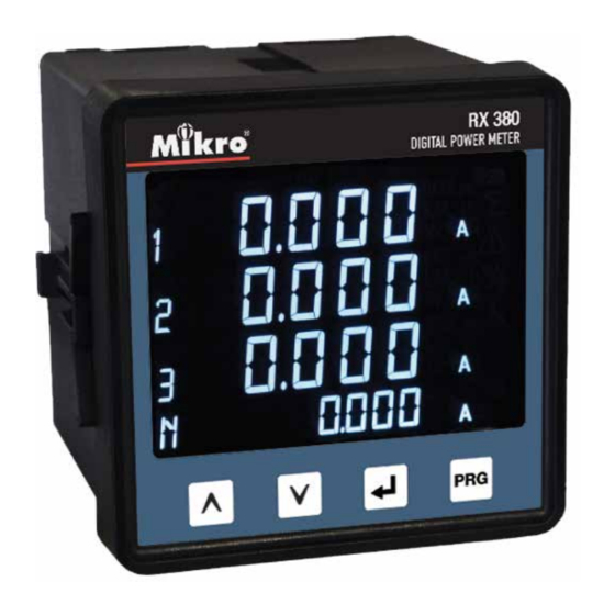
Page 6: Parts Of Power Meter
Connection to power the meter Voltage inputs Voltage metering connections Retainer clips Used to hold power meter in place. Retainer clips slot To slot-in retainer clips in place Table 3: Model information Model Information RX380 Auxiliary 90~415VAC or 100~300VDC; with Modbus... -
Page 7: Part Of Power Meter
2. Installation Guide 2.1. PRECAUTIONS Before installing the power meter, please check that the environment meets the following condition: • Operating temperature -10 Celcius to +55 Celcius. • Humidity 5% to 95%, non-condensing • Dust free environmental away from electrical noise and radiation 2.2. -
Page 8: Wiring
2.3. WIRING Figure 3: 3 Phase 4-Wire System with 4CTs connection, direct voltage input. Figure 4: 3-Phase 4-Wire System with 3CTs connection, direct voltage input. NOTE: Neutral current measurement is based on the vector sum of 3 CTs. -
Page 9: Phase 3-Wire With 3Cts And 3Vts
Figure 5 : 3-phase 3-wire with 3CTs and 3VTs connection. Figure 6: 3-phase 3-wire with 2CTs and 3VTs connection. NOTE: I2 current measurement is based on the vector sum of 2 CTs. -
Page 10: Meter Parameters
3. Meter parameters Before commencing operation, the meter has to be set up. To do this, the meter must be powered up by the meter control power supply. Under Section 6, the following parameters should be reviewed against the default value if necessary: •... -
Page 11: Function
5. Function Figure 7 below shows menu map for the power meter. It includes the setting and measurement display for the power meter. These menus can be accessed by pressing NEXT, UP, PROG & DOWN buttons. Min. Current Max Current Line Current (A) Phase Min. - Page 12 PROG Mode To change value range 5 - 9999A CT Ratio for primary and 5A for secondary Setting (A) To change value range 100 - 33kV for PT Ratio primary and 100 - 250V for secondary Setting (V ) Display Neutral Current Neutral Current (Measure / Calculate / Off) Setting (Ln)
-
Page 13: Setting Up
6. Setting up The power meter comes with factory default settings. These values may be changed by navigating to the appropriate screens and entering new values. Use the instructions in the following sections to change the values. 6.1. ACCESS PROGRAMMING MODE a. -
Page 14: Setup Pt Ratio
6.3. SETUP PT RATIO a. Scroll in programming mode until “Pt” is displayed using the UP or DOWN button. b. This parameter is to change the PT value if the Power Transformer (PT) is connected. c. Press the NEXT button to change. The “V” symbol for primary will blink. d. -
Page 15: Setup Communication Configuration
6.5. SETUP COMMUNICATION CONFIGURATIONS a. Scroll until ”ID BRATE PARITY“ is displayed using the UP or DOWN button. b. Press the NEXT button. The “PROG” and “-” symbol next to “ID” will blink. Use the UP or DOWN button to change the device ID. -
Page 16: System Setting
6.7. SYSTEM SETTING a. Scroll in programming mode until ”SYSt sEt“ is displayed using the UP or the DOWN button. b. Press the NEXT button. The “PROG” symbol will blink. Use the UP or DOWN button to toggle 3-phase 4-wire “3P4r”... -
Page 17: Reset Demand Register
6.9. RESET DEMAND REGISTER a. Scroll in programming mode until ”dMd rSt“ is displayed using the UP or the DOWN button. b. Press the NEXT button. The “PROG” symbol will blink. Use the UP or DOWN button to toggle “yES” or “no” symbols. -
Page 18: Remote Set
6.11. REMOTE SET a. Scroll until ”rMt SEt“ is displayed using the UP or the DOWN button. b. Press the NEXT button. The “PROG” symbol will blink. Use the UP or DOWN button to toggle Enable “on” or disable “oFF” symbols. c. -
Page 19: Scroll Delay Setting
6.13. SCROLL DELAY SETTING a. Scroll in programming mode until ”Scrl dELY“ is displayed using the UP or the DOWN button. b. This function is to set time interval for scroll window. c. Press the NEXT button. The “PROG” symbol will blink. Use the UP or DOWN button to set 1sec to 10secs interval. -
Page 20: Backlight Setting
6.15. BACKLIGHT SETTING a. Scroll in programming mode until ”bcLt“ is displayed using the UP or the DOWN button. b. This function is to turn off backlight after 5 minutes idle. c. Press the NEXT button. The “PROG” symbol will blink. Use the UP or DOWN button to toggle “oFF” or “on” symbols. -
Page 21: Setup New Password
6.18. SETUP THE PASSWORD Press the NEXT and PROG buttons simultaneously until the password ID request window is displayed. Key in the current password. Refer to Section 6.1 on how to do this. b. After pressing the PROG button, the “nEw id” window will be displayed. At this stage, the user needs to key in the new password. -
Page 22: Specifications
7. Specification Table 4: Specification Electrical Characteristic System 3P3W & 3P4W Current Display Three phase current & neutral(selectable) CT Primary 5-9999A CT Secondary Accuracy 0.5% (from 1A to 6A secondary) Sustained overload Voltage measurement PT Primary 100-33kV PT Secondary no PT, 100-250V Secondary Phase Voltage 20~300VAC Accuracy... - Page 23 Table 4: Specification (cont) Communication Hardware Interface Isolated RS485 Protocol Modbus-RTU 1 to 254 Baudrate 4800, 9600, 19200, 38400 Parity None (Stop Bit 1 and 2), even, odd Operating Condition Auxiliary Supply 90~415VAC or 100~300VDC Operating Temperature -10 C ~ +55 C Storage Temperature -20 C ~ +70 C Operating time (on hour)
-
Page 24: Modbus Data Register
8. Modbus Data Register 8.1 Data Type By default, the data format in each register is unsigned 16-bit word. Shorter data may be encoded in the unsigned 8-bit byte format whereas longer data may be encoded either in the unsigned 32-bit double word format, signed 32-bit integer format or signed 64-bit long integer format. -
Page 25: Operation Data Registers
Table 7: System status error register Read Only (Function 0x03 or 0x04) Register Description Type Range System Status Error flag word Error flag * Bit 15 = Voltage Sequence Error Bit 14 = Current Sequence Error Bit 10 = L3 Phase Loss Bit 9 = L2 Phase Loss Bit 8 = L1 Phase Loss Bit 7 = L3 Invalid Power Factor... - Page 26 Table 8: Operation data registers Read Only (Function 0x03 or 0x04) Register Description Type Min. Unit Range 4034-4035 Voltage Phase L1 dword 0.1V 0 ~ 999.9kV 4036-4037 Voltage Phase L2 dword 0.1V 0 ~ 999.9kV 4038-4039 Voltage Phase L3 dword 0.1V 0 ~ 999.9kV 4040-4041...
- Page 27 Table 8: Operation data register (cont) Read Only (Function 0x03 or 0x04) Min. Register Description Type Range Unit 4080 Displacement Power Factor L3 word 0.001 -1.000 ~ 1.000 4081 Displacement PF sign L3 word 0=Resistive; 1=ind; 2=cap 4082 THD Current L1 word 0.1% 0 ~ 1000...
- Page 28 Table 8: Operation data register (cont) Read Only (Function 0x03 or 0x04) Register Description Type Min. Unit Range 4104- 4105 Current L3 Max. dword 0.001A 0 ~ 999.9kA 4106-4107 Reserved 4108- 4109 Current Ln Max. dword 0.001A 0 ~ 999.9kA 4110-4111 Reserved 4112- 4113...
- Page 29 Table 8: Operation data register (cont) Read Only (Function 0x03 or 0x04) Register Description Type Min. Unit Range 4156- 4157 Max. Positive Real Power L3 0 ~ 999.9M 4158-4159 Reserved 4160- 4161 Max. Apparent Power L1 dword 0 ~ 999.9M 4162-4163 Reserved 4164- 4165...
- Page 30 Table 8: Operation data register (cont) Read Only (Function 0x03 or 0x04) Min. Register Description Type Range Unit 4202-4203 Reserved 4204- 4205 Voltage L2 Min. dword 0.1V 0 ~ 999.9kV 4206-4207 Reserved 4208- 4209 Voltage L3 Min. dword 0.1V 0 ~ 999.9kV 4210-4211 Reserved 4212- 4213...
- Page 31 Table 8: Operation data register (cont) Read Only (Function 0x03 or 0x04) Min. Register Description Type Range Unit 4248-4249 Apparent Power Min. L1 dword 0 ~ 999.9M 4250-4251 Reserved 4252-4253 Apparent Power Min. L2 dword 0 ~ 999.9M 4254-4255 Reserved 4256-4257 Apparent Power Min.
- Page 32 Table 8: Operation data register (cont) Read Only (Function 0x03 or 0x04) Min. Register Description Type Range Unit 4296-4297 Min. Negative Real Power L2 0 ~ 999.9M 4298-4299 Reserved 4300-4301 Min. Negative Real Power L3 0 ~ 999.9M 4302-4303 Reserved Total Negative Reactive Power 4304-4305 1VAR...
- Page 33 Table 9: Setting data register Read or write (Function 0x03,0x04 or 0x06) Register Description Range PT ratio primary 100 ~ 33kV PT ratio secondary no PT (‘0’), 100 ~ 250V CT ratio primary 5 ~ 9999A CT ratio secondary * Interval Demand 60 ~ 1800s Sub-Interval Demand...
-
Page 34: Maintenance And Troubleshooting
9. Maintenance and Troubleshooting The power meter does not contain any user-serviceable parts. If the power meter requires service, please contact your local sales representative. Do not open the power meter. Opening the power meter voids the warranty. NOTE: We reserve the right to alter or modify the information contained herein at any time in line with our product development without prior notification. -
Page 35: Appendix
11. Appendix 11.1. DEMAND CALCULATION Demand parameters are used to show average values over a demand interval.This power meter using sliding block method. The demand value is based on interval divide by sub-interval time. Example is shown below: SETTING: Interval time = 180 seconds ; sub-interval = 3 Measurement = interval time / sub-interval = 180 / 3 = 60 seconds ---------... -
Page 36: Neutral Current Calculation
11.3. NEUTRAL CURRENT CALCULATION The formula for neutral current, Ln is: √ A - AB - AC - BC where; A: Current Line 1 (A) B: Current Line 2 (A) C: Current Line 3 (A) Example Given L1 is 3A, L2 is 6A, L3 is 8A; Substitute into formula;...
Need help?
Do you have a question about the RX380 and is the answer not in the manual?
Questions and answers