
Related Manuals for Mikro DPM380


Summary of Contents for Mikro DPM380
- Page 1 Digital Power Meter User Manual DPM380 No.1, Jalan TP7/7, Sime UEP Industrial Park, 40400 Shah Alam, Selangor, Malaysia. Website: www.itmikro.com Tel: +(603)51927155 Fax: +(603)51927166...
- Page 2 Mikro shall not be liable for errors contained herein including any incidential and/or consequential damages arising from the use of this material. Mikro also reserves the right to vary the product from that described in this material without prior notice.
- Page 3 BEFORE YOU BEGIN • Apply appropriate personal protective equipment and follow safe electrical work practices. • NEVER work alone. • Turn-off all power supplying the power meter and the equipment in which it is installed before working on it. • Always use a properly rated voltage sensing device to confi...
-
Page 4: Table Of Contents
CONTENTS 1. Introduction 1.1.Content of box 1.2.Part of power meter 2. Installation Guide 2.1.Precautions 2.2.Mounting 2.3. Wiring 3. Meter parameters 4. Display and Buttons 5. Function 6. Setting up 6.1.Access programming mode 6.2.Setup CT ratio 6.3.Setup PT ratio 6.4.Neutral current 6.5.Setup communication confi... - Page 5 6.13. Scroll delay setting 6.14. Reset Hour on register 6.15. Backlight setting 6.16. Exit from programming mode 6.17. Setup new password 7. Specifi cations 8. Modbus table 9. Maintenance and troubleshooting 10. Dimensions 11. Appendix 11.1. Demand calculation 11.2. Data read format from modbus...
- Page 6 FIGURES 1. Parts of power meter 2. Recommendation cut-out 3. 3-phase 4-wire system with 4 CTs 4. 3-phase 4-wire system with 3 CTs 5. 3-phase 3-wire with 3CTs and 3VTs 6. 3-phase 3-wire with 2CTs and 3VTs 7. Menu map for the normal mode 8.
-
Page 7: Introduction
1.Introduction Thank you for purchasing the DPM380 Digital Power Meter. This multifunction power meter measuring the following parameters: • True RMS phase voltage ( L-N ) • True RMS line voltage (L-L ) • True RMS phase and neutral current •... -
Page 8: Part Of Power Meter
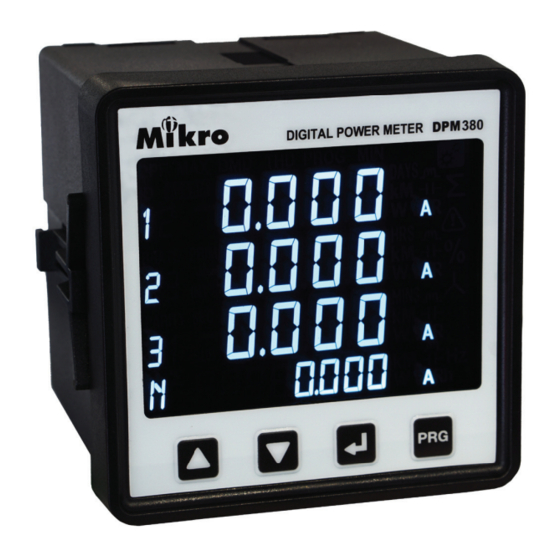
1.3. PARTS OF POWER METER CURRENT INPUTS ... / 5A (6A MAX.) Modbus RTU RS485 90V~415VAC VOLTAGE INPUT L-N 300V MAX. 50/60Hz 50/60Hz Category III 100V~300VDC Figure 1 : Parts of power meter Table 2: Location and part label Number Part Description Current inputs... -
Page 9: Model Information
Model Information DPM380-415AD Auxiliary 90~415VAC or 100~300VDC; with Modbus Table 3: Model information... -
Page 10: Installation Guide
2. Installation Guide 2.1. PRECAUTIONS Before installing the power meter,please check that the environment meets the following condition: • Operating temperature -10 Celcius to +55 Celcius. • Humidity 5% to 95%, non-condensing • Dust free environmental away from electrical noise and radiation 2.2. - Page 11 b) Insert the power meter through the hole and slide in the retainer clip along the slots on left and right sides or bottom and top sides of the power meter until the device is tightly secured on the switchgear panel. The orientation of the retainer clips is shown in fi...
- Page 12 e) When connecting the power meter, please make sure the polarity to the terminal is correctly aligned. f) If the Modbus-RTU is used, it can be connected up to 32 devices in a daisy chain fashion and the cable total length should not be more than 1000m.
-
Page 13: Wiring
2.3. WIRING Figure 3: 3 Phase 4-Wire System with 4CTs connection, direct voltage input. -
Page 14: Phase 4-Wire System With 3 Cts
Figure 4: 3-Phase 4-Wire System with 3CTs connection, direct voltage input. NOTE: Neutral current measurement is based on the 3 CTs. vector sum of... -
Page 15: Phase 3-Wire With 3Cts And 3Vts
Figure 5: 3-phase 3-wire with 3CTs and 3VTs connection. -
Page 16: Phase 3-Wire With 2Cts And 3Vts
Figure 6: 3-phase 3-wire with 2CTs and 3VTs connection. NOTE: I2 current measurement is based on the vector 2 CTs. sum of... -
Page 17: Meter Parameters
3. Meter parameters Before commencing operation, the meter has to be set up. To do this, the meter must be powered up by the meter control power supply. Under section 6, the following parameters should be reviewed against the default value if necessary: •... -
Page 18: Display And Buttons
4. Display and Buttons a. Setting Indicator h. ‘PROG’ button b. Total Indicator i. ‘NEXT’ button c. Alarm Indicator j. ‘DOWN’ button d. Percentage Indicator k. ‘UP’ button e. Unit Indicator l. Phase Indicator f. Capasitive/Inductive Indicator m. Window Indicator g. -
Page 19: Function
5. Function Figure 7 below shows menu map for the power meter. It includes the setting and measurement display for the power meter. These menus can be accessed by pressing NEXT, UP, PROG & DOWN buttons. Current Current Line Current (A) Max. -
Page 20: Flow Map For The Programming Mode
PROG Mode To change value range 5 - 9999A CT Ratio for primary and 5A for secondary Setting (A) PT Ratio To change value range 100 - 33kV for primary and 100 -120V for secondary Setting (V ) Neutral Current Setting (Ln) Demand Setting... -
Page 21: Setting Up
6. Setting up The power meter comes with factory default settings. These values may be changed by navigating to the appropriate screens and entering new values. Use the instructions in the following sections to change the values. 6.1. ACCESS PROGRAMMING MODE Press the PROG button to enter programming mode. -
Page 22: Setup Ct Ratio
6.2. SETUP CT RATIO CT ratio setting is the fi rst item display in programming mode. Press the NEXT button to change. The fi rst digit will blink. Use the UP or DOWN button to change the primary CT value. Press the NEXT button for the next digit. -
Page 23: Setup Pt Ratio
6.3. SETUP PT RATIO Scroll in programming mode until ”Pt“ is displayed using the UP or DOWN button. This parameter is to change the PT value if the Power Transformer (PT) is connected. Press the NEXT button to change. The “V” symbol for primary will blink. -
Page 24: Neutral Current
6.4. NEUTRAL CURRENT Scroll in programming mode until ”Ln“ is displayed using the UP or DOWN button. This parameter is to display neutral current if the neutral current (Ln) is connected. Press the NEXT button to change. The “PROG” symbol will blink. -
Page 25: Setup Communication Confi Guration
6.5. SETUP COMMUNICATION CONFIGURATIONS Scroll until ”ID BRATE PARITY“ is displayed using the UP or DOWN button. Press the NEXT button. The “PROG” and “-” symbol next to “ID” will blink. Use the UP or DOWN button to change the device ID. Next, press the NEXT button and “-”symbol next to “BRATE”... -
Page 26: Demand Setting
6.6. DEMAND SETTING Scroll until ”DMD“ is displayed using the UP or DOWN button. Press the NEXT button to change interval value. The “PROG” symbol will displayed and “-”symbol next to “INT” will blink. Use UP or DOWN button to change value and press NEXT button to confi... -
Page 27: System Setting
6.7. SYSTEM SETTING Scroll in programming mode until ”SYSt sEt“ is displayed using the UP or the DOWN button. Press the NEXT button. The “PROG” symbol will blink. Use the UP or DOWN button to toggle 3-phase 4-wire “3P4r” or 3-phase 3-wire “3P3r” symbols. Press the NEXT button to confi... -
Page 28: Reset All Energy Register
6.8. RESET ALL ENERGY REGISTER Scroll in programming mode until ”EnEr rSEt“ is displayed using the UP or the DOWN button. Press the NEXT button. The “PROG” symbol will blink. Use the UP or DOWN button to toggle “YES” or “NO” symbols. -
Page 29: Reset Demand Register
6.9. RESET DEMAND REGISTER Scroll in programming mode until ”dMd rSt“ is displayed using the UP or the DOWN button. Press the NEXT button. The “PROG” symbol will blink. Use the UP or DOWN button to toggle “YES” or “NO” symbols. -
Page 30: Reset Maximum & Minimum Value
6.10. RESET MAXIMUM AND MINIMUM VALUE Scroll until ”rSEt“ is displayed using the UP or the DOWN button. Press the NEXT button. The “PROG” symbol will blink. Use the UP or DOWN button to toggle “YES” or “NO” symbols. To abort clearing max. and min. values, select “NO”. To clear all max. -
Page 31: Remote Set
6.11. REMOTE SET Scroll until ”rMt SEt“ is displayed using the UP or the DOWN button. Press the NEXT button. The “PROG” symbol will blink. Use the UP or DOWN button to toggle Enable “ON” or disable “OFF” symbols. Press the NEXT button to confi rm new setting. To proceed next setting press DOWN button. -
Page 32: Scroll Mode Setting
6.12. SCROLL SETTING Scroll in programming mode until ”Scrl SEt“ is displayed using the UP or the DOWN button. This function is to turn ON/OFF scroll mode. If turn on, when the display is idle the meter will shows each window in normal mode base on the scroll delay setting time. -
Page 33: Scroll Delay Setting
6.13. SCROLL DELAY SETTING Scroll in programming mode until ”Scrl dELY“ is displayed using the UP or the DOWN button. This function is to set time interval for scroll window. Press the NEXT button. The “PROG” symbol will blink. Use the UP or DOWN button to set 1sec to 10secs interval. -
Page 34: Reset Hour On Register
6.14. RESET HOUR-ON REGISTER Scroll in programming mode until ”Hron rSt“ is displayed using the UP or the DOWN button. This function is to clear hour-on register. Press the NEXT button. The “PROG” symbol will blink. Use the UP or DOWN button to toggle “YES” or “NO” symbols. -
Page 35: Backlight Setting
6.15. BACKLIGHT SETTING Scroll in programming mode until ”bcLt“ is displayed using the UP or the DOWN button. This function is to turn off backlight after 10minutes idle. Press the NEXT button. The “PROG” symbol will blink. Use the UP or DOWN button to toggle “OFF” or “ON” symbols. -
Page 36: Exit From Programming Mode
6.16. EXIT FROM PROGRAMMING MODE If select “Yes” Use the PROG button exit from programming mode window. Any changes made in the setting will be prompted to confi rm saving. The “SAVE SET” display will appear. Use the UP or DOWN button to select “YES” or “NO” symbols. -
Page 37: Setup New Password
6.17. SETUP THE PASSWORD Press the NEXT and PROG buttons simultaneously until the password ID request window is displayed. Key in the current password. Refer to section 6.1 on how to do this. After pressing the PROG button, the “new id” window will be displayed. - Page 38 Next, the “SAVE SEt” will be displayed. Use the UP or DOWN buttons to toggle the ”YES“ and ”NO“ symbols to save the new password. Once confi rmed, press the PROG button and the meter will return to normal display mode.
-
Page 39: Specifi Cations
7. Specifi cation Electrical Characteristic System 3P3W & 3P4W Current Display Three phase current & neutral(selectable) CT Primary 5-9995A CT Secondary Accuracy 0.5% (from 1A to 6A secondary) Sustained overload Voltage measurement PT Primary 100-33kV PT Secondary 100-250V, no PT Secondary Phase Voltage 20~300VAC Accuracy 0.5%... - Page 40 Table 4: Specifi cation (cont) Frequency measurement Range 45~65Hz Accuracy 0.5% Energy measurement Active IEC62053-21:Class 1 Reactive IEC62053-23:Class 2 Demand measurement Demand interval 60 to 1800 seconds Demand sub-interval 1 to 120 Communication Hardware Interface Isolated RS485 Protocol Modbus-RTU 1 to 255 Baudrate 2400, 4800, 9600, 19200, 38400...
- Page 41 Table 4: Specifi cation (cont) Mechanical Characteristic Dimension Case L96mm x W96mm x H105mm Mounting type Panel LCD view area 76mmx56.5mm Weight 480g Electromagnetic Compatibility (EMC) Part 6-2: Generic Immunity for industrial Standards IEC61000-6-2 environments Part 6-4: Generic Emission standard for Standards IEC61000-6-4 industrial environments...
-
Page 42: Modbus Table
8. Modbus Data Register 8.1 Data Type By default, the data format in each register is unsigned 16- bit word. Shorter data may be encoded in the unsigned 8-bit byte format whereas longer data may be encoded either in the unsigned 32-bit double word format, signed 32-bit integer format or signed 64-bit long integer format. -
Page 43: Device And Communication Register
Table 6: Device and communication register Read Only (Function 0x03 or 0x04) Reserved Device Type Version Read Only (Function 0x03 or 0x04) 1000 Device ID 1-255 1001 Parity 1=none 2=even 3=odd 1002 Baudrate 1=2400 2=4800 3=9600 4=19200 5=38400 Table 7: Operation data registers Read Only (Function 0x03 or 0x04) Min. - Page 44 Table 7: Operation data register (cont) Read Only (Function 0x03 or 0x04) Min. Register Description Type Range Unit 4008- Negative Reactive dword 1kVArh 0~1000000M 4009 Energy 4010- Positive Reactive dword 1kVArh 0~1000000M 4011 Energy 4012- Total Real Power -2000M~2000M 4013 4014- Total Apparent dword...
- Page 45 Table 7: Operation data register (cont) Read Only (Function 0x03 or 0x04) Min. Register Description Type Range Unit 4032- Voltage Phase dword 0.1V 0~999.9kV 4033 4034- Voltage Phase L1 dword 0.1V 0~999.9kV 4035 4036- Voltage Phase L2 dword 0.1V 0~999.9kV 4037 4038- Voltage Phase L3...
- Page 46 Table 7: Operation data register (cont) Read Only (Function 0x03 or 0x04) Min. Register Description Type Range Unit 4058- Total Demand 1VAR -2000M~2000M 4059 Reactive Power 4060- Max.Total Demand 1VAR -2000M~2000M 4061 Reactive Power 4062- Reserved 4063 4064- Total Demand Real -2000M~2000M 4065 Power...
- Page 47 Table 7: Operation data register (cont) Read Only (Function 0x03 or 0x04) Min. Register Description Type Range Unit Displacement Power 4080 word 0.001 0 ~ 1.000 Factor L3 0=Resistive; Displacement PF 4081 word sign L3 1=ind; 2=cap 4082 THD Current L1 word 0.1% 0 ~ 1000...
- Page 48 Table 7: Operation data register (cont) Read Only (Function 0x03 or 0x04) Min. Register Description Type Range Unit 0=Resistive; Sign Total Power 4095 word Factor 1=ind; 2=cap 4096- Current L1 Max. dword 0.001A 0~999.9kA 4097 4098- Reserved 4099 4100- Current L2 Max. dword 0.001A 0~999.9kA...
- Page 49 Table 7: Operation data register (cont) Read Only (Function 0x03 or 0x04) Min. Register Description Type Range Unit 4120- Voltage L3 dword 0.1V 0~999.9kV 4121 Max. 4122- Reserved 4123 Voltage L12 4124- dword 0.1V 0~999.9kV 4125 Max. 4126- Reserved 4127 Voltage L23 4128- dword...
- Page 50 Table 7: Operation data register (cont) Read Only (Function 0x03 or 0x04) Min. Register Description Type Range Unit 4146- Reserved 4147 4148- Max. Real -2000M~2000M 4149 Power L1 4150- Reserved 4151 4152- Max. Real -2000M~2000M 4153 Power L2 4154- Reserved 4155 4156- Max.
- Page 51 Table 7: Operation data register (cont) Read Only (Function 0x03 or 0x04) Min. Register Description Type Range Unit 4170- Reserved 4171 Max. Reactive 4172- 1VAR -2000M~2000M 4173 Power L1 4174- Reserved 4175 Max. Reactive 4176- 1VAR -2000M~2000M 4177 Power L2 4178- Reserved 4179...
- Page 52 Table 7: Operation data register (cont) Read Only (Function 0x03 or 0x04) Min. Register Description Type Range Unit 4196- Current Ln Min. dword 0.001A 0~999.9kV 4197 4198- Reserved 4199 4200- Voltage L1 Min. dword 0.1V 0~999.9kV 4201 4202- Reserved 4203 4204- Voltage L2 Min.
- Page 53 Table 7: Operation data register (cont) Read Only (Function 0x03 or 0x04) Min. Register Description Type Range Unit 4222- Reserved 4223 4224- Total Real -2000M~2000M 4225 Power Min. 4226- Reserved 4227 4228- Total Apparent dword 0~2000M Power Min. 4229 4230- Reserved 4231 4232-...
- Page 54 Table 7: Operation data register (cont) Read Only (Function 0x03 or 0x04) Min. Register Description Type Range Unit 4248- Apparent dword 0~2000M 4249 Power Min. L1 4250- Reserved 4251 4252- Apparent dword 0~2000M Power Min. L2 4253 4254- Reserved 4255 4256- Apparent dword...
-
Page 55: Setting Data Registers
Read or write (Function 0x03,0x04 or 0x06) Register Description Range PT ratio primary 100~33kV PT ratio secondary 100~250V CT ratio primary 5~9995A CT ratio secondary Interval Demand 60~1800s Sub-Interval Demand 1~120 System Confi guration 3P4W/ 3P3W Backlight setting ON/OFF System scroll setting ON/OFF Scroll interval 1-10 secs... -
Page 56: Maintenance And Troubleshooting
9. Maintenance and Troubleshooting The power meter does not contain any user-serviceable parts. If the power meter requires service, please contact your local sales representative. Do not open the power me- ter. Opening the power meter voids the warranty. NOTE: We reserve the right to alter or modify the information contained herein at any time in line with our product de- velopment without prior notifi... -
Page 57: Dimensions
10. Meter Dimension Front 96mm 17.5mm Rear 105mm... - Page 58 1 2 3 4 5 6 7 8 9 10 11 12 13 14 90.5mm 15 16 17 18 19 20 Back 90.5mm...
-
Page 59: Appendix
11. Appendix 11.1. DEMAND CALCULATION 11.1. DEMAND CALCULATION Demand parameters are used to show average values over a demand interval.This power meter using sliding block method. The demand value is based on interval divide by sub-interval time. Example is shown below: SETTING: Interval time = 180 seconds ;... -
Page 60: Data Read Format From Modbus
11.2. DATA READ FORMAT FROM MODBUS 11.2. DATA READ FORMAT FROM MODBUS a) 4000-4001 : Negative Real Energy Address 4000 Address 4001 0x00 0x01 0x23 0x34 Negative Real Energy = 0x00012334 =74548 x 1kWh (min value) =74548kWh b) 4012-4013 : Total Real Power; (Signed register) Address 4012 Address 4013 0xFF...
Need help?
Do you have a question about the DPM380 and is the answer not in the manual?
Questions and answers