
Related Manuals for Mikro DPM380


Summary of Contents for Mikro DPM380
- Page 1 Digital Power Meter User Manual DPM380/DPM380B No.3, Jalan Anggerik Mokara 31/48, Seksyen 31, Kota Kemuning, 40460 Shah Alam, Selangor, Malaysia Website: www.itmikro.com Tel: +(603)5525 3863 Fax: +(603)5525 3873...
- Page 2 Mikro shall not be liable for errors contained herein including any incidental and/or consequential damages arising from the use of this material. Mikro also reserves the right to vary the product from that described in this material without prior notice.
-
Page 3: Table Of Contents
CONTENTS 1. Introduction 1.1. Content of box 1.2. Part of power meter 2. Installation Guide 2.1. Precautions 2.2. Mounting 2.3. Wiring 3. Meter parameters 4. Display and Buttons 5. Function 6. Setting up 6.1. Access programming mode 6.2. Setup CT ratio 6.3. - Page 4 Demand Calculation 11.2. Data Read Format from Modbus * 11.3. Neutral Current Calculation *- Applicable for DPM380 only FIGURES 1. Parts of power meter 2. Recommendation cut-out 3. 3-phase 4-wire system with 4 CTs 4. 3-phase 4-wire system with 3 CTs 5.
-
Page 5: Introduction
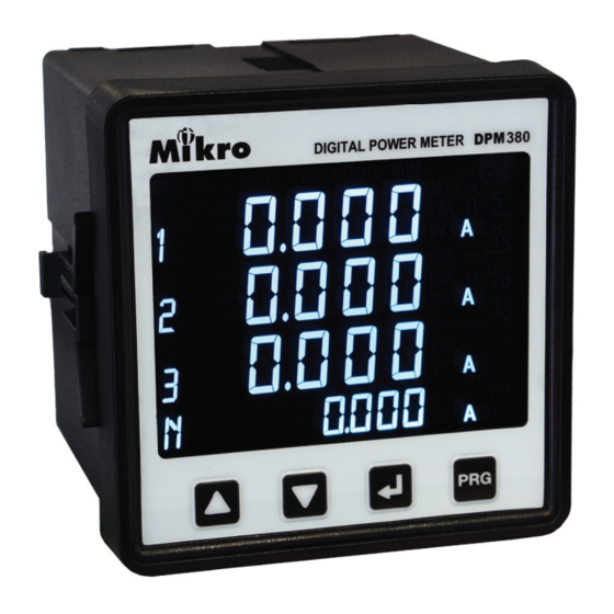
1. Introduction Thank you for purchasing the DPM380 / DPM380B Digital Power Meter. This multifunctional power meter measures the following parameters: • True RMS phase voltage ( L - N ) • True RMS line voltage ( L - L ) •... -
Page 6: Part Of Power Meter
Voltage metering connections Retainer clips Used to hold power meter in place. Retainer clips slot To slot-in retainer clips in place *- Applicable for DPM380 only Table 3: Model information Model Information DPM380 Auxiliary 90~415VAC or 100~300VDC; with Modbus DPM380B... -
Page 7: Installation Guide
If the Modbus-RTU* is used, it can be connected up to 32 devices in a daisy chain fashion and the cable total length should not be more than 1000m. NOTE: For Modbus-RTU* connection, avoid running the cable near sources of electrical noise. The network cable shield should be grounded at only one end. *- Applicable for DPM380 only... -
Page 8: Wiring
2.3. WIRING *- Applicable for DPM380 only Figure 3: 3 Phase 4-Wire System with 4CTs connection, direct voltage input. *- Applicable for DPM380 only Figure 4: 3-Phase 4-Wire System with 3CTs connection, direct voltage input. NOTE: Neutral current measurement is based on the vector sum of 3 CTs. -
Page 9: Phase 3-Wire With 3Cts And 3Vts
*- Applicable for DPM380 only Figure 5 : 3-phase 3-wire with 3CTs and 3VTs connection. *- Applicable for DPM380 only Figure 6: 3-phase 3-wire with 2CTs and 3VTs connection. NOTE: I2 current measurement is based on the vector sum of 2 CTs. -
Page 10: Meter Parameters
Total Indicator c. Alarm Indicator d. Percentage Indicator e. Unit Indicator f. Capacitive/Inductive Indicator g. Digit Display h. ‘PROG’ button i. ‘NEXT’ button j. ‘DOWN’ button k. ‘UP’ button l. Phase Indicator m. Window Indicator *- Applicable for DPM380 only... -
Page 11: Function
5. Function Figure 7 below shows menu map for the power meter. It includes the setting and measurement display for the power meter. These menus can be accessed by pressing NEXT, UP, PROG & DOWN buttons. Current Current Line Current (A) Max. -
Page 12: Flow Map For The Programming Mode
To set interval time for scroll display (1-10secs) Time Reset Hour- Reset (Yes/No) On Register Backlight To turn off backlight after minutes of idle (On/Off) Setting Software Version Figure 8 : Menu map for programming mode *- Applicable for DPM380 only... -
Page 13: Setting Up
6. Setting up The power meter comes with factory default settings. These values may be changed by navigating to the appropriate screens and entering new values. Use the instructions in the following sections to change the values. 6.1. ACCESS PROGRAMMING MODE a. -
Page 14: Setup Ct Ratio
6.2. SETUP CT RATIO a. CT ratio setting is the first item displayed in programming mode. b. Press the NEXT button to change. The first digit will blink. c. Use the UP or DOWN button to change the primary CT value. d. -
Page 15: Neutral Current
Neutral current default setting is measured value 6.5. SETUP COMMUNICATION CONFIGURATIONS * *- Applicable for DPM380 only a. Scroll until ”ID BRATE PARITY“ is displayed using the UP or DOWN button. b. Press the NEXT button. The “PROG” and “-” symbol next to “ID” will blink. Use the UP or DOWN button to change the device ID. -
Page 16: Demand Setting
6.6. DEMAND SETTING a. Scroll until ”DMD“ is displayed using the UP or DOWN button. b. Press the NEXT button to change interval value. The “PROG” symbol will displayed and “-” symbol next to “INT” will blink. c. Use UP or DOWN button to change value and press NEXT button to confirm and change sub-interval setting. The “-”... -
Page 17: Reset All Energy Register
6.8. RESET ALL ENERGY REGISTER a. Scroll in programming mode until ”EnEr rSt“ is displayed using the UP or the DOWN button. b. Press the NEXT button. The “PROG” symbol will blink. Use the UP or DOWN button to toggle “yES” or “no” symbols. -
Page 18: Reset Maximum & Minimum Value
Refer Section 6.16. 6.11. REMOTE SET * *- Applicable for DPM380 only a. Scroll until ”rMt SEt“ is displayed using the UP or the DOWN button. b. Press the NEXT button. The “PROG” symbol will blink. Use the UP or DOWN button to toggle Enable “on”... -
Page 19: Scroll Setting
6.12. SCROLL SETTING a. Scroll in programming mode until ”Scrl SEt“ is displayed using the UP or the DOWN button. b. This function is to turn ON/OFF scroll mode. If turn on, when the display is idle the meter will shows each window in normal mode base on the scroll delay setting time. -
Page 20: Reset Hour On Register
6.14. RESET HOUR-ON REGISTER a. Scroll in programming mode until ”Hron rSt“ is displayed using the UP or the DOWN button. b. This function is to clear hour-on register. c. Press the NEXT button. The “PROG” symbol will blink. Use the UP or DOWN button to toggle “yES” or “no” symbols. -
Page 21: Exit From Programming Mode
6.17. EXIT FROM PROGRAMMING MODE If select “Yes” Use the PROG button exit from programming mode window. Any changes made in the setting will be prompted to confirm saving. The “SAVE SET” display will appear. Use the UP or DOWN button to select “yES” or “no” symbols. To exit without saving the new value, select “no”... -
Page 22: Specifications
7. Specification Table 4: Specification Electrical Characteristic System 3P3W & 3P4W Current Display Three phase current & neutral(selectable) CT Primary 5-9999A CT Secondary Accuracy 0.5% (from 1A to 6A secondary) Sustained overload Voltage measurement PT Primary 100-33kV PT Secondary no PT, 100-250V Secondary Phase Voltage 20~300VAC Accuracy... - Page 23 L96mm x W96mm x H87.5mm Mounting type Panel LCD view area 76mm x 56.5mm Weight 450g Electromagnetic Compatibility (EMC) Part 6-2: Generic Standards IEC61000-6-2 Immunity for industrial environments Part 6-4: Generic Standards IEC61000-6-4 Emission standard for industrial environments *- Applicable for DPM380 only...
-
Page 24: Modbus Data Register
Read Only (Function 0x03 or 0x04) 1000 Device ID 1-255 1001 Parity 1 = none 2 = even 3 = odd 1002 Baudrate 1 = 2400 2 = 4800 3 = 9600 4 = 19200 5 = 38400 *- Applicable for DPM380 only... -
Page 25: Operation Data Registers
Table 7: Operation data registers Read Only (Function 0x03 or 0x04) Register Description Type Min. Unit Range 4000- Negative Real Energy dword 1kWh 0 ~ 1000000M 4001 4002-4003 Positive Real Energy dword 1kWh 0 ~ 1000000M 4004-4005 Reserved 4006-4007 Apparent Energy dword 1kVAh 0 ~ 1000000M... - Page 26 Table 7: Operation data register (cont) Read Only (Function 0x03 or 0x04) Min. Register Description Type Range Unit 4052-4053 Reactive Power L1 1VAR -2000M ~ 2000M 4054-4055 Reactive Power L2 1VAR -2000M ~ 2000M 4056-4057 Reactive Power L3 1VAR -2000M ~ 2000M 4058- Total Demand Reactive Power 1VAR...
- Page 27 Table 7: Operation data register (cont) Read Only (Function 0x03 or 0x04) Register Description Type Min. Unit Range 4085 THD Voltage L1 word 0.1% 0 ~ 1000 4086 THD Voltage L2 word 0.1% 0 ~ 1000 4087 THD Voltage L3 word 0.1% 0 ~ 1000...
- Page 28 Table 7: Operation data register (cont) Read Only (Function 0x03 or 0x04) Register Description Type Min. Unit Range 4120- 4121 Voltage L3 Max. dword 0.1V 0 ~ 999.9kV 4122-4123 Reserved 4124- 4125 Voltage L12 Max. dword 0.1V 0 ~ 999.9kV 4126-4127 Reserved 4128- 4129...
- Page 29 Table 7: Operation data register (cont) Read Only (Function 0x03 or 0x04) Min. Register Description Type Range Unit 4170-4171 Reserved 4172- 4173 Max. Reactive Power L1 1VAR -2000M ~ 2000M 4174-4175 Reserved 4176- 4177 Max. Reactive Power L2 1VAR -2000M ~ 2000M 4178-4179 Reserved 4180- 4181...
- Page 30 Table 7: Operation data register (cont) Read Only (Function 0x03 or 0x04) Min. Register Description Type Range Unit 4220-4221 Voltage L31 Min. dword 0.1V 0 ~ 999.9kV 4222-4223 Reserved 4224-4225 Total Real Power Min. -2000M ~ 2000M 4226-4227 Reserved 4228-4229 Total Apparent Power Min.
- Page 31 Table 7: Operation data register (cont) Read Only (Function 0x03 or 0x04) Min. Register Description Type Range Unit 4248-4249 Apparent Power Min. L1 dword 0 ~ 2000M 4250-4251 Reserved 4252-4253 Apparent Power Min. L2 dword 0 ~ 2000M 4254-4255 Reserved 4256-4257 Apparent Power Min.
-
Page 32: Setting Data Registers
Table 8: Setting data register Read or write (Function 0x03,0x04 or 0x06) Register Description Range PT ratio primary 100 ~ 33kV PT ratio secondary no PT, 100 ~ 250V CT ratio primary 5 ~ 9999A CT ratio secondary Interval Demand 60 ~ 1800s Sub-Interval Demand 1 ~ 120... -
Page 33: Maintenance And Troubleshooting
9. Maintenance and Troubleshooting The power meter does not contain any user-serviceable parts. If the power meter requires service, please contact your local sales representative. Do not open the power meter. Opening the power meter voids the warranty. NOTE: We reserve the right to alter or modify the information contained herein at any time in line with our product development without prior notification. -
Page 34: Appendix
11. Appendix 11.1. DEMAND CALCULATION Demand parameters are used to show average values over a demand interval.This power meter using sliding block method. The demand value is based on interval divide by sub-interval time. Example is shown below: SETTING: Interval time = 180 seconds ; sub-interval = 3 Measurement = interval time / sub-interval = 180 / 3 = 60 seconds ---------... -
Page 35: Neutral Current Calculation
11.3. NEUTRAL CURRENT CALCULATION The formula for neutral current, Ln is: √ A - AB - AC - BC where; A: Current Line 1 (A) B: Current Line 2 (A) C: Current Line 3 (A) Example Given L1 is 3A, L2 is 6A, L3 is 8A; Substitute into formula;...
Need help?
Do you have a question about the DPM380 and is the answer not in the manual?
Questions and answers