PairGain HLU-231 Manual
Hide thumbs
Also See for HLU-231:
- Manual (77 pages) ,
- Quick installation manual (20 pages) ,
- Manual (42 pages)
Table of Contents
Advertisement
Quick Links
Model
HLU-231
E
NGINEERING
H
G
L
I
AIN
INE
List Number
8
HLU 231
H G
I AIN
HDSL
MODE
SEL
STATUS
BRG
SPAN
D
S
X
BRG
1
SPAN
L
8
PairGain
P
G
T
AIR
AIN
ECHNOLOGIES
S
ERVICES
150-231-108-04
U
NIT
Part Number
150-1111-08
LINE UNIT
MARGIN
dB
XMT
RCV
R
S
2
3
2
, I
.
NC
T
P
ECHNICAL
RACTICE
CLEI Code
T1L2FY0A
Advertisement
Table of Contents
Troubleshooting

Related Manuals for PairGain HLU-231


Summary of Contents for PairGain HLU-231
- Page 1 Model List Number Part Number CLEI Code HLU-231 150-1111-08 T1L2FY0A HLU 231 LINE UNIT I AIN MARGIN HDSL MODE STATUS SPAN SPAN PairGain ECHNOLOGIES NGINEERING ERVICES ECHNICAL RACTICE 150-231-108-04...
- Page 2 Information furnished by PairGain Technologies is believed to be accurate and reliable. However, no responsibility is assumed by PairGain Technologies for its use; nor for any infringement of patents or other rights of third parties which may result from its use.
- Page 3 Check the packing list to ensure complete and accurate shipment of each listed item. If the shipment is short or irregular, contact PairGain as described in the Warranty located inside the back cover. If you must store the equipment for a prolonged period, store the equipment in its original container.
- Page 4 Inspecting the Shipment 150-231-108-04, Revision 04 August 13, 1999 HLU-231 List 8...
-
Page 5: Table Of Contents
View Span Status Screen ....................15 Span Status Screen without Doublers ..............16 Span Status Screen for Doubler Applications .............16 Set Clock Screen........................19 Set Time ......................19 Set Date .......................19 Update the HRU Time and Date .................19 HLU-231 List 8 August 13, 1999... - Page 6 Troubleshooting _____________________________________________________________________ 40 System Alarms..........................40 Alarm Option for DLC Feed ..................... 41 Retiring System Alarms ....................41 Self Test ..........................41 Loopback Operation ........................42 Generic Loopback Commands..................42 Special Loopback Commands................... 44 August 13, 1999 HLU-231 List 8...
- Page 7 Power Consumption .........................53 Power Consumption without Doublers................53 Power Consumption with Doublers...................54 Maximum Power Dissipation......................56 Maximum Current Drain........................56 HLU-231 List 8 Card Connector .....................57 Network Management Control Bus ...................57 Fuse Alarm ........................57 System Alarm Relay Output....................58 Craft Port............................58 Appendix B - Functional Operation _____________________________________________________ 59 Timing ..............................59...
- Page 8 IST OF IGURES 1. HLU-231 List 8 Front Panel ........................... 4 2. Installing the HLU-231 List 8 into a Shelf ..................... 8 3. Maintenance Terminal Main Menu ......................14 4. System Spans ..............................15 5. Span Status Screen: No Doubler........................16 6.
- Page 9 17. HLU-231 Power Parameters—No Doubler....................53 18. HLU-231 Power Parameters—Single Doubler (HDU-451 List 1 or 2) ............54 19. HLU-231 Power Parameters—Single Doubler (HDU-439 or HDU-437 Lists 1 and 1B) ......54 20. HLU-231 Power Parameters—Single Doubler (HDU-409 List 2) ..............54 21. HLU-231 Power Parameters—Two Doublers (HDU-451 List 3, 4, 3B or 4B) ..........55 22.
- Page 10 List of Tables 150-231-108-04, Revision 04 August 13, 1999 HLU-231 List 8...
-
Page 11: Overview
The PairGain HiGain Line Unit HLU-231 List 8 is the Central Office (CO) side of a repeaterless T1 transmission system. When used in conjunction with a HiGain Remote Unit (HRU), the system provides 1.544 Mbps transmission on two unconditioned copper pairs over the full Carrier Service Area (CSA) range. The CSA includes loops up to 12,000 feet of 24 AWG or 9,000 feet of 26 AWG wire, including bridged taps. -
Page 12: Compatibility
Margin threshold alarm OMPATIBILITY The HLU-231 List 8 is designed to mount in 220 mechanics shelves. For a list of compatible shelves, see “Appendix C - Compatibility” on page All generations of HiGain HLU and HRU modules are compatible with each other. To take advantage of the enhanced features of newer HiGain doublers, refer to “HiGain Doubler Circuit Deployment”... -
Page 13: Personal Communications System Applications
Overview Personal Communications System Applications The HLU-231 List 8 is required for Personal Communications System (PCS) applications that use the HRU-411. The HRU-411 has an onboard 130 Vdc, 8.5 W power supply that can power the 200 mW PCS remote radio ports. -
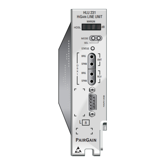
Page 14: Front Panel
Front Panel 150-231-108-04, Revision 04 RONT ANEL The HLU-231 List 8 front panel is shown in Figure 1. The front-panel components are described in Table 1. For pinout diagrams of the HLU card-edge connector and the craft port, refer to “Appendix A - Specifications”... - Page 15 Flashing red System alarm Yellow Self Test is in process or an HLU-231 List 8 Customer Remote Loopback (CREM) or a Network Local Loopback (NLOC) is in effect. Flashing yellow HLU-231 List 8 is Armed to respond to Intelligent Repeater Loop (ILR) codes.
-
Page 16: Front-Panel Display Messages
CODE xxxx Line Code: AMI, B8ZS, AUTO The line code that HLU-231 List 8 is receiving at its DSX-1 interface, if the DS1 option is set to Auto. Otherwise, it mimics either of the other two DS1 line code settings, Alternate Mark Inversion (AMI) or Bipolar with 8-zero Substitution (B8ZS). - Page 17 LBPV Local Bipolar Violation A bipolar violation has been received at the T1 input to the HLU-231. LIST xxxx HLU-231 List Number The software list number (xxxx) appears during the System Settings review mode.
-
Page 18: Installation
When installing an HLU in a chassis, be sure to wear an antistatic wrist strap. Avoid touching components on the circuit board. Slide the HLU-231 into the card guides of the desired slot, then push the unit back until it touches the backplane card-edge connector and the retaining latch on the front panel opens... -
Page 19: Verification
150-231-108-04, Revision 04 Installation ERIFICATION Once the HLU-231 is installed, verify that it is operating properly. To do this, you need to monitor the following: • Status LED • Status messages reported by the front-panel display (see Table 2 on page... -
Page 20: Provisioning Requirements
Clear the Span Status, Performance Data, and Performance History screens. This can be accomplished by & pressing (clear) at the Span Status screen (see “View Span Status Screen” on page 15). Clear the Alarm History screens (see “View Alarm History Screen” on page 33). August 13, 1999 HLU-231 List 8... -
Page 21: Provisioning
150-231-108-04, Revision 04 Provisioning ROVISIONING This is a reference section for HLU provisioning. There are two methods for provisioning the HLU-231 List 8: • Use the MODE and SEL buttons on the front panel of the HLU to: – set system options –... -
Page 22: Resetting To Factory Default Values
If the system is in a Minor alarm state, the alarm relay can be disengaged by pressing the SEL button. This turns off the Alarm Cut-off (ACO) indication. Loopback Modes “Loopback Operation” on page 42 for instructions on using the MODE and SEL buttons to activate loopbacks. August 13, 1999 HLU-231 List 8... -
Page 23: Using A Maintenance Terminal
Connecting to a Maintenance Terminal The craft port on the front panel allows you to connect the HLU-231 to a maintenance terminal (ASCII terminal or PC running a terminal emulation program). Once connected to a maintenance terminal, you can access the maintenance, provisioning, and performance screens. -
Page 24: Maintenance Terminal Main Menu
The function of each screen selection is listed in Table 4. To access a screen, type the letter shown next to the menu item. HIGAIN HLU-231 MAINTENANCE TERMINAL MAIN MENU (ver V7.0L-8) CIRCUIT ID#: A. VIEW SPAN STATUS B. SET CLOCK C. -
Page 25: Selecting A Maintenance Terminal Function
As shown in Figure 4, the HLU can support up to four doublers with five HDSL spans. The Span Status, Performance Data, and Performance History may display as many five screens to depict an HLU-231 List 8 system. Figure 4. System Spans... -
Page 26: Span Status Screen Without Doublers
DS1 STATUS 24 HOUR ES Count: 00000 00017 24 HOUR UAS Count: 00000 00012 Frame type: Code type: AUTOUPDATE OFF (E)xit (C)lear (A)uto(U)pdate (S)pan(1)(2)(3)(4)(5) Figure 6. Span Status Screen: Four Doublers (Span 5) August 13, 1999 HLU-231 List 8... -
Page 27: Span Status Fields And Descriptions
LLOS, RLOS, LAIS, or RAIS. RCV (xxxx) - Signal received (xxxx) at the T1 input to either the HLU or HRU. XMT (xxxx) - Signal transmitted (xxxx) at the T1 output of either the HLU or HRU. HLU-231 List 8 August 13, 1999... -
Page 28: Loopback Messages
NLOC Network Local Loopback Loopback HLU-231 (local) to network initiated from CO by IOR code, the MODE and SEL buttons on the HLU-231 front panel, or by the maintenance terminal. NREM Network Remote Loopback Loopback at HRU to network initiated from CO (network) by ILR #2 code, the MODE and SEL buttons on the HLU-231 front panel, the HRU manual loopback button, or by the maintenance terminal. -
Page 29: Set Clock Screen
Update the HRU Time and Date The remote unit date and time is set by using this option. Do one of the following: • Press to update the HRU to the same date and time set for the HLU-231 List 8. • Press (17(5 . -
Page 30: System Settings Screen
System Settings Screen The options set from the System Settings screen are the same as the options set through the HLU-231 Mode and SEL buttons on the front panel. The exceptions are Margin Alarm Threshold and DS0 Blocking, which can only be set at this screen. -
Page 31: Hlu-231 List 8 System Settings
150-231-108-04, Revision 04 Provisioning Table 8 describes the System Settings options and lists the corresponding front-panel display codes. Factory default parameters appear in boldface type. Table 8. HLU-231 List 8 System Settings Front-panel System Settings Display Parameter Description Screen Options... - Page 32 AIS on HDSL LOSW HAIS Causes the HiGain system to transmit the AIS signal at both the HLU-231 and HRU T1 output ports when both of the HDSL loops are not in sync (LOSW). (See “HAIS Option”...
-
Page 33: Equalization Option
Standard HDSL systems correct T1 BPVs at the input and thus prevent them from being detected by the DLC terminals to which they are connected. The HLU-231 and its associated remote units remove this limitation and become BPV transparent by detecting and counting input BPVs at each end and then replicating them at the T1 output port of the distant end. -
Page 34: Ber Option
If DS0 blocking is invoked in a HiGain system that has an earlier version HRU that does not support the blocking option, blocking only occurs at the DSX-1 output of the HLU-231 List 8. The HRU DS1 output is not blocked. -
Page 35: Margin Alarm Threshold Option
(zero) for the margin threshold turns the margin alarm off. HAIS Option The HAIS option provides two selections for the T1 transmit outputs at both the HLU-231 and HRU for HDSL loss of sync conditions. • 1LP causes the AIS (LOS if ALMP is set to LOS) pattern to be transmitted at both T1 outputs when either of the two HDSL loops experience an out-of-sync (LOSW) condition or when a margin alarm occurs. -
Page 36: Loopback Mode Screen
Provisioning 150-231-108-04, Revision 04 If the HLU-231 is used with the HRU-411 to power PCS sites, the PWRF option should be set to AUTO. This causes the HLU to automatically detect the need to switch to the HIGH power feed mode when it receives a request from the HRU to do so. -
Page 37: Loopback Menu Without Doubler
H. CUSTOMER LOOP HRU (CLOC) I. CUSTOMER LOOP DOUBLER 1 (CDU1) J. CUSTOMER LOOP DOUBLER 2 (CDU2) K. NETWORK LOOP DOUBLER 3 (NDU3) L. CUSTOMER LOOP DOUBLER 3 (CDU3) (E)xit Figure 10. Loopback Menu: Four Doublers HLU-231 List 8 August 13, 1999... -
Page 38: Initiating A Loopback
NLOC loopback is in progress). The loopback continues to cycle in the system depending upon your Loopback Timeout setting. The Loopback Menu screen is also available at the HRU connected to the HLU-231 List 8, thus allowing all HiGain System loopbacks to be initiated from either end of the circuit. -
Page 39: View Performance Data Screen
Figure 5 on page 16. The HLU-231 is considered the master module; it clears all performance data screens at both the HLU-231 and the HRU. Counters can not be cleared by accessing the HRU craft port. Table 10. Errored and Unavailable Seconds Definitions... -
Page 40: Performance Data Screen Without Doubler
150-231-108-04, Revision 04 Performance Data Screen without Doubler Figure 12 shows a single non-doubler span. This screen shows the Errored and Unavailable Seconds for the HDSL span between the HLU-231 and the HRU. Date: 07/05/99 PERFORMANCE DATA CIRCUIT ID#: ERRORED SECONDS/UNAVAILABLE SECONDS... -
Page 41: View Performance History Screen
Figure 5 on page 16. The HLU-231 is considered the master module; it clears all performance data screens at both the HLU-231 and the HRU. Counters can not be cleared by accessing the HRU craft port. Performance History Screen without Doubler Figure 14 shows a non-doubler application. -
Page 42: Performance History Screen For Doubler Applications
01/24 01/25 01/26 01/27 01/28 01/29 00001/ 00005/00415 00035/00492 01/30 01/31 00001/ 00002/00002 00004/00014 00006/ 00003/00013 00007/00001 current 00001/ 00005/00415 00035/00492 (E)xit (P)revious (S)pan(1)(2)(3)(4)(5) Figure 15. 31-Day Performance History Screen: Four Doublers (Span 5) August 13, 1999 HLU-231 List 8... -
Page 43: View Alarm History Screen
PWR-SHRT Power short condition; current condition, number of alarms PWR-GND Power ground condition; current condition, number of alarms Last Cleared: Last time Alarm History cleared; current condition, number of alarms HLU-231 List 8 August 13, 1999... -
Page 44: Alarm History Screen Without Doubler
02/01/99-00:00 SPAN5 LOSW, HDSL2 02/01/99-00:00 02/01/99-00:00 SPAN5 MARGIN L1 02/01/99-00:00 02/01/99-00:00 SPAN5 MARGIN L2 02/01/99-00:00 02/01/99-00:00 PWR-SHRT PWR-GND LAST CLEARED: 03/04/99-13:49 (E)xit (C)lear (U)pdate (S)pan(1)(2)(3)(4)(5) Figure 17. Alarm History Screen: Four Doublers (Span 5) August 13, 1999 HLU-231 List 8... -
Page 45: View System Inventory Screen
• All detected modules have the product number listed. Whenever the HLU-231 loses sync with Span 1, the product types are replaced by the N/A label until sync is reestablished and each module can in turn be reidentified. Only the Circuit ID appears in the other HLU-231 List 8 Terminal Maintenance screens. -
Page 46: System Inventory Screen Without Doubler
Remote Unit C. DB1 HDU-404 V1.2 D. DB2 HDU-404 V1.2 F. DB3 HDU-404 V1.2 G. DB4 HDU-404 V1.2 (E)xit Enter the item letter to change the ID Figure 19. System Inventory Screen: Four Doublers August 13, 1999 HLU-231 List 8... -
Page 47: View Troubleshooting Screen
DS1 Loss of Signal T1 is not detected at input to unit Alarm Indication Signal Far end LOS, HDSL LOSW, loopbacks or MAL AUTOUPDATE OFF (E)xit (A)uto(U)pdate (H)elp (L)oopbacks Figure 21. Troubleshooting Screen Describing Circuit Problem HLU-231 List 8 August 13, 1999... -
Page 48: Troubleshooting With Help
Errors include BPV, framing, CRC and LOS DS1 Loss of Signal T1 is not detected at input to unit Alarm Indication Signal Far end LOS, HDSL LOSW, loopbacks or MAL AUTOUPDATE OFF (E)xit (A)uto(U)pdate (B)ack Figure 22. Troubleshooting with Help August 13, 1999 HLU-231 List 8... -
Page 49: Troubleshooting With Margin Values
High insertion loss is the result of a low received HDSL signal. Some causes of high insertion loss: Long loop Bridged taps AUTOUPDATE OFF (E)xit (A)uto(U)pdate (B)ack Figure 24. Troubleshooting with Insertion Loss Values HLU-231 List 8 August 13, 1999... -
Page 50: Troubleshooting
Cannot be inhibited. (a) When both HDSL loops lose sync word (LOSW), a system alarm condition exists. However, since the HLU-231 enters a self test cycling mode, the front-panel LED lights yellow instead of red and the SELF TEST message displays instead of the ALRM message. -
Page 51: Alarm Option For Dlc Feed
Alarm Option for DLC Feed To improve HiGain compatibility with the switch-to-protect features used in DLC feeder applications, the HLU-231 has an Alarm Pattern Option (ALMP) that allows you to select either an AIS or LOS T1 output payload for the following alarms: •... -
Page 52: Loopback Operation
Table 13 on page 43 summarizes the HiGain generic loopback commands. See “GNLB Test Procedures” on page 46 for the test procedures that apply when using the GNLB mode. Figure 25. Loopback Summary August 13, 1999 HLU-231 List 8... - Page 53 MODE and SEL buttons. Use the inband commands to enable or disable the SMJK loopback options. The HLU-231 system setting is normally enabled to recognize all inband SmartJack loopback commands.
-
Page 54: Special Loopback Commands
These additions make A1LB identical to A2LB. A1LB is given a separate identity to allow future T1/E1 enhancements to be added without affecting A2LB. A5LB differs from A2LB in that A5LB does not block the arming code from exiting the HLU-231 into the network. A2LB can be configured to do one of the following: •... -
Page 55: Initiating A Manual Loopback Session
Once a loopback is selected and activated, the loopback stays active until it times out (based on the LBTO setting). When a loopback times out, the display then returns to the normal display mode. HLU-231 List 8 August 13, 1999... -
Page 56: Loopback Test Procedures
NREM message on the front-panel display. (The Status LED on the front panel should be green, and the loopback mode should also be identified on the Span Status screen.) Have the CO tester transmit a T1 test signal towards the HLU-231 and verify that the returned (looped) signal to the test set is error-free. - Page 57 150-231-108-04, Revision 04 Troubleshooting Figure 26. Loopback Configurations HLU-231 List 8 August 13, 1999...
-
Page 58: A1Lb, A2Lb, And A5Lb Test Procedures
A tester at the customer premises can activate CLOC or CREM loopbacks. All loopbacks shown in Table 14 can also be initiated from the HLU-231 front-panel MODE and SEL buttons (see “Setting Options through MODE and SEL” on page 11). - Page 59 To perform the A1LB, A2LB, and the A5LB test procedures: Send the inband Arming and NI LPBK code 11000 to the HLU-231 for at least 5 seconds. Monitor the output of the HLU-231 for the return of the pattern. Return of the pattern indicates one of the following: •...
- Page 60 Alternate query • Far end activate • Another ARM command. This timer is inhibited while any of the valid command codes are being sent. Once the codes are removed, the timer restarts at 120. August 13, 1999 HLU-231 List 8...
-
Page 61: A3Lb And A4Lb Test Procedures
16-bit loop-up command before the timer expires. When this time-out override state exists, the only way to loop the HLU-231 down is to issue one of the three loopdown commands listed in Table 15. -
Page 62: Appendix A - Specifications
1.4 in. (3.5 cm) Depth: 10 in. (25.4 cm) Weight: 8 oz. (.23 kg) Wander (Looped) 0.3 UI maximum (1 UI = 648 ns) WB Jitter (Looped) 0.2 UI maximum NB Jitter (Looped) 0.1 UI maximum August 13, 1999 HLU-231 List 8... -
Page 63: Hdsl Insertion Loss Guidelines
1.54 (a) At 196 kHz, 68°F (20°C) A Windows-based program, Cable Calculator, may be downloaded from the Customer site portion of the PairGain web site at www.pairgain.com . If you don’t have a customer password, contact your sales representative. OWER... -
Page 64: Power Consumption With Doublers
Table 24 list the power consumed and dissipated by the HLU-231 when it is used with any of the four basic doubler types in the HiGain family. The maximum current drawn by the CO supply is also listed. Table 18... -
Page 65: Hlu-231 Power Parameters-Two Doublers (Hdu-451 List 3, 4, 3B Or 4B)
Table 21 through Table 23 show power parameters for two doubler, line-powered circuits on 9 kft, 26 AWG loops. Table 21. HLU-231 Power Parameters—Two Doublers (HDU-451 List 3, 4, 3B or 4B) HRU CPE 42.5 Vdc Power HRU Model No. -
Page 66: Maximum Power Dissipation
The 42.5 Vdc Power Consumption is the maximum total power that the HLU-231 consumes or draws from the shelf power source. This parameter is needed when the HLU-231 is in a location remote to the CO it is serving. It determines the battery capacity required to maintain an 8-hour, stand-by battery reserve for emergency situations. -
Page 67: Hlu-231 List 8 Card Connector
Figure 27. HLU-231 List 8 Card-edge Connector Network Management Control Bus The HLU-231 List 8 provides a Network Management Control Bus on pin 46 of the card-edge connector. This allows the various PairGain Management System protocols to manage the HLU through the HMU-319 HiGain Management Unit. -
Page 68: System Alarm Relay Output
The normally open alarm contacts available across pins 20 and 21 (Figure 27 on page 57) comprise the HLU-231 List 8 system alarm output. These alarm contacts close for any system alarms condition. (See “View Troubleshooting Screen” on page 37 for further information.) -
Page 69: Appendix B - Functional Operation
Figure 29. HLU-231 List 8 Block Diagram IMING The low loop wander (0.3 UI max) of an HLU-231 List 8, when used with compatible doublers (HDU-409, HDU-404 or HDU-407) and remote units (HRU-402 or HRU-411), allows the circuit to be used in all critical timing applications, including those that are used to transport Stratum 1 timing. -
Page 70: Ground Fault Detect
ETECT The HLU-231 has a Ground Fault Detect (GFD) circuit which detects a ground or a resistive path to ground on any wire of any loop of any span with a non-zero voltage. For low (-140 Vdc) applications, such a circuit is active during start-up by applying the bipolar voltage to the loops. -
Page 71: Appendixc - Compatibility
HiGain system complies with GR-63-CORE, TR-TSY-000499, and GR-1089-CORE. T1 R EPEATER HELVES AND ELATED QUIPMENT The HLU-231 List 8 is compatible with the following T1 repeater shelves and associated equipment: • PairGain HCS-417 (23”) • PairGain HCS-418 (19”) • PairGain HCS-402 (2-slot)) •... - Page 72 (a) HRU-411 applications with I -CPE “on” are limited to single doubler circuits (HDU-404, HDU-407 or HDU-409) using HLU-231, Lists 8/8D/8E; HLU-319, Lists 5/5D/5E; and HLU-388 Lists 5/5D/5E. The HRU-412, HDU-451, HDU-437 and HDU-439 are limited to applications with one and two doublers only.
-
Page 73: Appendixd - Product Support
PairGain Customer Service Group provides expert pre-sales and post-sales support and training for all its products. ECHNICAL UPPORT Technical assistance is available 24 hours a day, 7 days a week by contacting PairGain Customer Service Group at: (800) 638-0031 or (714) 832-9922 Telephone: The 800 telephone support line is toll-free in the U.S. - Page 74 If there is another reason for returning the equipment, please let us know so we can determine how best to help you. Pack the equipment in a shipping carton. Write PairGain’s address and the Return Material Authorization Number you received from Customer Service clearly on the outside of the carton: PairGain Technologies, Inc.
-
Page 75: Appendix E - Glossary
Network Equipment Building System Digital Data Service National Electric Code Disabled Network Interface Digital Loop Carrier Network Interface Device Digital Signal, level 0 Network Interface Unit Digital Signal, level 1 NLOC Network Local Loopback HLU-231 List 8 August 13, 1999... - Page 76 Pulse Position Modulation Total Error Count PWRF Power Feed TLOS-LB Transmit Loss of Signal-Loopback Receive TSEC Total System Error Count Remote DS1 Alarm TSGR Transport System Generic Requirements RLOS Remote Loss of Signal Unavailable Seconds Transmit August 13, 1999 HLU-231 List 8...
-
Page 77: Certification And Warranty
Do not try to repair the unit. If it fails, replace it with another unit and return the faulty unit to PairGain for repair. Any modifications of the unit by anyone other than an authorized PairGain representative voids the warranty. - Page 78 Corporate Office 14402 Franklin Avenue Tustin, CA 92780 Tel: (714) 832-9922 Fax: (714) 832-9924 For Technical Assistance: (800) 638-0031...
Need help?
Do you have a question about the HLU-231 and is the answer not in the manual?
Questions and answers