
Related Manuals for Oxford Semiconductor OX16PCI952

Summary of Contents for Oxford Semiconductor OX16PCI952
- Page 1 UG-0013 May 05 OX16PCI952 Evaluation Board User Guide Oxford Semiconductor Limited 25 Milton Park Abingdon Oxfordshire OX14 4SH, UK (44) 1235 824900 http://www.oxsemi.com...
- Page 2 The content of this manual is furnished for informational use only, is subject to change without notice, and should not be construed as a commitment by Oxford Semiconductor Limited. Oxford Semiconductor Limited assumes no responsibility or liability for any errors or inaccuracies that may appear in this book.
-
Page 3: Table Of Contents
Contacting Oxford Semiconductor ........vi... - Page 4 Contents OX16PCI952 Evaluation Board User Guide Appendix A Drivers ........... . . 11 Driver Process .
-
Page 5: Preface
Preface The OX16PCI952 evaluation board provides an environment in which the various modes and features of the OX16PCI952 device can be demonstrated. This guide documents the board and explains how to use it to develop systems using the Oxford Semiconductor OX16PCI952 device. It is... -
Page 6: Product Details
Preface OX16PCI952 Evaluation Board User Guide Product The order code for the OX16PCI952 evaluation board is EV-OX16PCI952. Details Contacting Oxford Semiconductor contact details: Oxford Oxford Semiconductor Ltd. Semiconductor 25 Milton Park Abingdon Oxfordshire OX14 4SH United Kingdom Website: http://www.oxsemi.com Telephone:... -
Page 7: Chapter 1 Evaluation Board Overview
(switchable) Configuration The evaluation board is a valuable tool for assessing the behavior of the OX16PCI952 device and can be configured to support systems using the following selectable capabilities: 2-port serial (1 × RS232, 1 × RS422)/1-port parallel card 2-port serial (1 ×... -
Page 8: Drivers
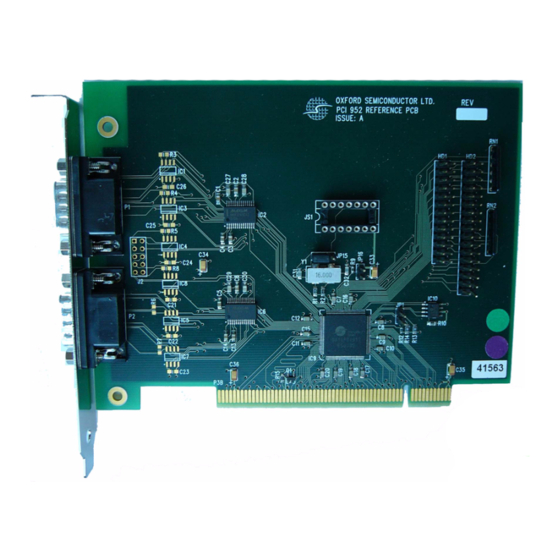
Evaluation Board Overview OX16PCI952 Evaluation Board User Guide Drivers The drivers provided for the OX16PCI952 evaluation board have been written for Windows 2000, Windows NT and Windows XP operating systems. Contact Oxford Semiconductor for details of drivers written for Linux and other operating systems. - Page 9 9-Way D Type IC10 OXPCI952 EEPROM PCI Edge Connector For greater detail, a reference schematic for the OX16PCI952 evaluation board can be requested from Oxford Semiconductor. Chapter 2 Evaluation Board Features gives further details about the features of the OX16PCI952 evaluation board.
- Page 10 Evaluation Board Overview OX16PCI952 Evaluation Board User Guide This page is intentionally blank External—Free Release UG-0013 May 05...
-
Page 11: Chapter 2 Evaluation Board Features
Chapter 2 Evaluation Board Features The OX16PCI952 evaluation board contains a variety of sockets, jumpers, connectors and headers, which enhance its flexibility. Jumpers Table 1 details the jumpers on the board and their use. Table 1 Jumpers on the OX16PCI952 Evaluation Board... -
Page 12: Headers & Connectors
J2, which is the 5×2 DTR/DSR header for the RS422 channel on the evaluation board. The OX16PCI952 supports one RS422 port. Data transfer rates are much greater using RS422 protocol, because it uses differential signalling. However, RS422 connectors only allow for CTS/RTS flow control. J2 provides access to the hardware lines necessary to provide DTR/DSR flow control in addition to conventional CTS/RTS flow control. -
Page 13: Chapter 3 Configuring The Evaluation Board
The IDs used for the primary device modes covered in this chapter are hard-coded and should not be changed. However, the OX16PCI952 is flexible and can be used for other solutions, which require their own IDs. Appendix C Customizing the Device Vendor ID &... -
Page 14: Device Modes
Configuring the Evaluation Board OX16PCI952 Evaluation Board User Guide Device Header JP1 on the OX16PCI952 evaluation board is used to select the device mode. The location of JP1 is shown in Figure 2 on page 3. Modes Selecting the Device Mode Table 2 shows how the mode pins are used to select the device mode. -
Page 15: Eeprom Configuration Using Oxprom
Configuring the Evaluation Board Implementing One Serial/One Parallel Port Although the standard device modes for the OX16PCI952 use two serial ports, it is possible to configure only one, with a parallel port if required, which illustrates the flexibility of the device. -
Page 16: Interrupts
OX16PCI952 Evaluation Board User Guide Interrupts Interrupts in PCI systems are level-sensitive and can be shared. In the OX16PCI952, there are five interrupt sources—one from each UART channel, two from multi-purpose I/O pins (MIO0 and MIO1), and one from the parallel port. -
Page 17: Appendix A Drivers
Drivers Reference drivers and utilities for the Oxford Semiconductor UART products are supplied to demonstrate functionality under Windows operating systems. These drivers have been tested using Oxford Semiconductor development boards in a range of PC systems. Driver software and any accompanying files are provided ‘as is’ and without warranties as to performance or merchantability, or any other warranties whether express or implied. -
Page 18: Using The Serial Driver
OX16PCI952 Evaluation Board User Guide Using the The serial drivers are highly configurable. They make use of a number of enhanced features for the Oxford Semiconductor 950-series UARTs. Serial Driver This section describes the configuration utilities that can be used to enable and configure driver features. - Page 19 OX16PCI952 Evaluation Board User Guide Drivers This tag also allows users to select RS232, RS422, or RS485 half-duplex operation. The following points are worth noting for these options: For RS232 applications the DTR pin should be configured as normal For RS485, the driver can configure the DTR pin as either active-...
-
Page 20: Using The Parallel Port Driver
Click the + by Ports (COM & LPT) to review the installed PCI COM ports. Double-click the appropriate Oxford Semiconductor PCI Parallel port to display the settings dialog for that port Click the Port Settings tab and enable or disable the interrupt as required External—Free Release... - Page 21 OX16PCI952 Evaluation Board User Guide Drivers Win 9x & Windows ME Parallel Port Configuration The parallel port driver sets the hardware to use legacy addresses 378h if available, otherwise it uses the address allocated by the system BIOS. Windows allocates an LPT number (e.g. LPT2) to the port; then it can be used in the same fashion as any generic parallel port.
- Page 22 Drivers OX16PCI952 Evaluation Board User Guide This page is intentionally blank External—Free Release UG-0013 May 05...
-
Page 23: Appendix B Rs422 & Rs232 Connector Pin Assignment
RS422 & RS232 Connector Pin Assignment This appendix discusses the use of RS422 and RS232 9-pin and 25-pin connectors in systems using the device evaluation board. RS422 Figure 4 shows how RS422 ports are connected on 9-way D-connectors. Connector Figure 4 RS422 Pin Assignments Pins TXD–... -
Page 24: Db9-To-Db25 Converter
RS422 & RS232 Connector Pin Assignment OX16PCI952 Evaluation Board User Guide Figure 5 RS232 DB 9 Pin-Assignment Data Carrier Detect Data Set ready Receive Data Request-to-Send Transmit Data Clear-to-Send Data Terminator Ready Ring Indicator Signal Ground Protective Ground Figure 6 shows the RS232 DB 25-pin assignment. -
Page 25: Rs232 Loop-Back Test Plugs
OX16PCI952 Evaluation Board User Guide RS422 & RS232 Connector Pin Assignment Figure 7 RS232 DB9-to-DB25 Converter RS232 The following connectors can be used to test a PC serial port. The data Loop-Back and handshake lines are linked so that all data is sent back immediately. -
Page 26: Rs232 Null Modem Cables
RS422 & RS232 Connector Pin Assignment OX16PCI952 Evaluation Board User Guide Figure 9 RS232 Loop-Back Test Plug for Norton Diagnostics & CheckIt RS232 Null The easiest way of connecting two PCs is via a null modem cable, although the situation is complicated by the variety of null-modem Modem cables available. -
Page 27: Rs232 Monitor Cable
OX16PCI952 Evaluation Board User Guide RS422 & RS232 Connector Pin Assignment Figure 11 Null Modem with Loop-Back Handshaking Figure 12 Null Modem with Partial Handshaking Figure 13 Null Modem with Full Handshaking RS232 Figure 14 shows an RS232 cable that can be used to monitor the serial monitor cable communication between two devices using a PC. - Page 28 RS422 & RS232 Connector Pin Assignment OX16PCI952 Evaluation Board User Guide The monitor cable taps communication from both sides, which means that the monitored information is garbage if the two devices happen to communicate simultaneously. However, because most communication software works in half-duplex mode, this problem does not arise.
-
Page 29: Appendix C Customizing The Device Vendor Id & Subsystem Id
ID fields with the new value; then choose a device ID & subsystem ID. Leave the vendor ID & device ID as the Oxford Semiconductor default values. Obtain a subsystem vendor ID from the PCISIG & use OxProm to reprogram the subsystem vendor ID fields with the new value;... -
Page 30: Examples
It is not possible to limit the hardware to enable only two serial ports, so this solution requires a driver in the enumerator driver, which ensures that it only registers two ports. Oxford Semiconductor reserves device ID 0x950A for this, so the recommended solution is as shown in... - Page 31 One Parallel Port Only It is not possible to disable the UARTs on the device, so this solution requires the user to install a null driver for them. Oxford Semiconductor has assigned a device ID for this (value 0x9500), so the recommended...
- Page 32 Customizing the Device Vendor ID & Subsystem ID OX16PCI952 Evaluation Board User Guide This page is intentionally blank External—Free Release UG-0013 May 05...
-
Page 33: Appendix D Troubleshooting
These support higher data transfer rates, but do not interface to RS232 ports. Ensure that the correct ports are in use 3 Ensure that the port has a clock signal, either from the OX16PCI952 oscillator, or from the TTL clock module. This is selected with XTALsel (internal UARTs) and CLKsel... - Page 34 Troubleshooting OX16PCI952 Evaluation Board User Guide Table 7 Driver Issues (Sheet 1 of 3) Problem Response If the EEPROM is programmed To make the OS accept the card, try the following: with an invalid image it may: not 1 Unplug the board from the system.
- Page 35 .inf files for a driver to be loaded. Oxprom.exe and 15M operation The Oxford Semiconductor NT driver does not support 15M. OxProm does not work in NT. does not work in NT We can release source code under NDA UG-0013 May 05 External—Free Release...
- Page 36 Troubleshooting OX16PCI952 Evaluation Board User Guide Table 7 Driver Issues (Sheet 3 of 3) Problem Response How can the device be set up to Make a change in the oxpci.inf file as follows: use only one serial port? [PCI_9521.NT.HW] AddReg=PCI_9521.NT.HW.AddReg [PCI_9521.NT.HW.AddReg]...
Need help?
Do you have a question about the OX16PCI952 and is the answer not in the manual?
Questions and answers