Advertisement
Quick Links
1.
Intent & Scope
This document describes the installation procedure for the ICM-400 series intercom stations. The ICM-400 series
intercom stations include intercom stations types ICM-420, ICM-421, ICM-430, ICM-431, and ICM-490. The ICM-
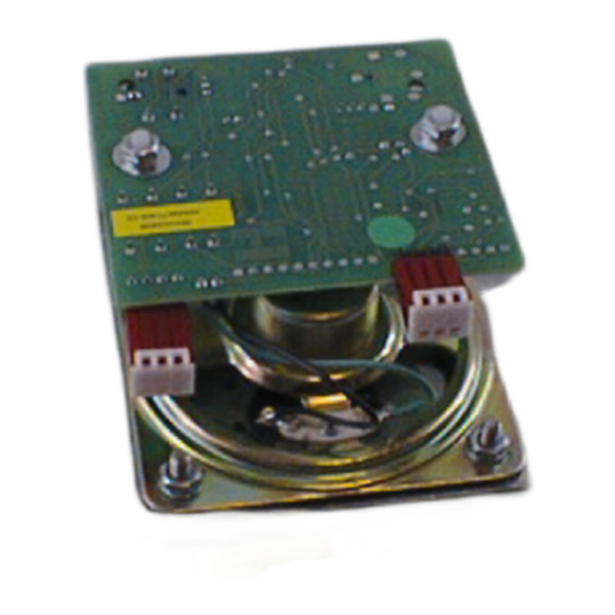
4x1 stations include a LED while the ICM-4x0 stations do not. The ICB-400 Intercom Board is used to convert a 45
ohm loudspeaker into a 400 series intercom station. Included is a description on connecting an ICM-420 and ICM-
320 to create a two sided door primary/secondary pair
2.
Description
The ICM-400 series of intercom stations include all intercom stations that are connected to a DXI system via a
SAB-400 or SAB-401 station audio board, or to a DXL system via a SCC-400 or SCC-401 station control card. Each
ICM-400 series intercom station is connected to the system with a single shielded twisted pair cable that carries all
the microphone, loudspeaker, switch, and LED indicator signals.
The ICM-400 series intercom stations can be ordered in several configurations. These include:
(i)
0, 1 or 2 switches. These switches are mounted on the faceplate and internally terminated. They can be
used for call request, program music selection, or other functions. The terminations allow the system to
detect open or short line faults.
The switch information is multiplexed with the audio signals over a single pair of wires.
(ii)
The LED stations, ICM-421 and ICM-431, are used with SAB-401 station audio board or SCC-401 station
control card. The LED is used to indicate call request status or active call status. Again LED status
information is multiplexed over the audio pair.
(iii)
A cord jack can be specified in place of the standard faceplate switch on the intercom stations.
(iv)
An Apem switch, red mushroom button switch or mini-piezo switch can be ordered for the intercom
stations.
(v)
A piezo-electric switch can be specified in place of the standard faceplate switch on the ICM-430 or ICM-
431
(vi)
The switch contacts of a switch can be made available on a four-pin header. With external field wiring the
switch can then be used to operate an external device, i.e. open a door; turn on lights, etc. External
contacts can also be connected to this four-pin header. This allows external equipment to activate the
station switches and place call requests or act as a switch to change the music selection.
Document IM-ICM-400-2.14
ICM-400 Series Intercom Stations
1999 Harding Instruments - Printed in Canada
Advertisement

Subscribe to Our Youtube Channel
Related Manuals for Harding Instruments dxi MicroComm ICM-400 Series


Summary of Contents for Harding Instruments dxi MicroComm ICM-400 Series
- Page 1 This allows external equipment to activate the station switches and place call requests or act as a switch to change the music selection. 1999 Harding Instruments - Printed in Canada Document IM-ICM-400-2.14...
- Page 2 ICM-400 Series Intercom Stations (vii) The ICB-400 Intercom Board kit is used to convert a 45 ohm loudspeaker into a 400 type of intercom station. Page 2 Document IM-ICM-400-2.14...
-
Page 3: Installation
ICM-400 Series Intercom Stations Pin 1 Pin 1 Rear View of ICM-420 Intercom Station with connectors CN1 and CN3 installed Installation A simplified diagram of the back view of the ICM-420 is shown below. The header CN1 is always present and is used to connect audio, programmable switch information and LED status between the system and the intercom station. - Page 4 ICM-400 Series Intercom Stations 4.50" 2001 Harding Instrument Co. Ltd. Aud + PC06713-04 Aud - Aud - Aud + Spkr + Spkr- Sw B In - Switch B In + Switch B Out - Switch B Out + Switch A In - Switch A In + Switch A Out - Switch A Out +...
- Page 5 ICM-400 Series Intercom Stations jacket should be trimmed back about 1/2 inch. Ensure that the shield is not exposed or it may short out exposed contacts on the intercom PCB when it is installed. Document IM-ICM-400-2.14 Page 5...
- Page 6 ICM-400 Series Intercom Stations The pin configuration of the station connector is: MTA Pin Signal Audio + Audio - MTA Pin Signals To insert the signal wires into the connector you remove the white cover from the connector, insert the connector into the tool from the left side (it will travel through the tool in the direction indicated by the arrow), pull the trigger once to load the connector.
- Page 7 ICM-400 Series Intercom Stations The switch connections can optionally be ordered as pigtail leads, a 4-pin MTA–100 connector or as a 4-pin MTA- 100 connector with pigtail leads. 2.50" 2001 Harding Instrument Co. Ltd. Aud + Aud - PC06713-04 Aud - Aud + Spkr + Spkr-...
- Page 8 ICM-400 Series Intercom Stations Connections to transformer from Spkr+ and Spkr- Trim and insulate unused transformer tap leads Trim and insulate unused switch leads Talkback Kit Installation Complete Make the electrical connections to the talkback kit for the loudspeaker and optional switches. The loudspeaker connection must be made to a 45-ohm loudspeaker, or through a matching transformer.
- Page 9 ICM-400 Series Intercom Stations Two Sided Door Primary/Secondary Pair The two sided Door Primary/Secondary paired stations are meant to provide an intercom on both sides of a door but require only one SAB channel. This is achieved by paralleling the speaker and switch of the secondary station to the circuitry of the primary station.
- Page 10 ICM-400 Series Intercom Stations 4.50" Minimum Opening 3.625"W x 2.875" H x 1.75"D 1.81" Switch A Switch B 4 Mounting Holes 0.188" (3/16") 6.38" Minimum Opening 5.437"W x 2.875" H x 1.75"D 3.63" Switch A Switch B 1.50" 4 Mounting Holes 0.188" (3/16") 6.38"...
Need help?
Do you have a question about the dxi MicroComm ICM-400 Series and is the answer not in the manual?
Questions and answers