Advertisement
1.
Intent & Scope
This document describes the installation procedure for the IEB-400 intercom board. The intercom board is used to
interface with 8 ohm intercom stations to obtain full MicroComm DXL quality and performance. The board can
also be used to transform 8 ohm ceiling loudspeakers and an external call switch into an intercom station.
2.
Description
The IEB-400 intercom boards are connected to a DXI system via a SAB-400 or SAB-401 station audio board, or to a
DXL system via a SCC-400 or SCC-401 station control card. Each IEB-400 intercom station is connected to the
system via a 4-pin header and a single shielded twisted pair cable that carries all the microphone, loudspeaker,
switch, and LED indicator signals.
An 8-pin header is used to connect the IEB-400 intercom board to an 8 ohm loudspeaker, up to two switches and
an LED.
PCB06741-06
MicroComm
ICE-400 Station
CN2
Component Side
3.
Installation
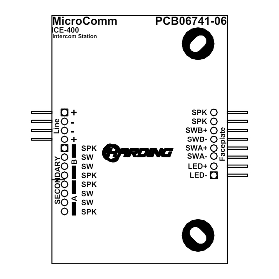
A simplified diagram of an IEB-400 is shown in Figure 1. The 4-pin header CN8 connect the audio lines to the
DXL or DXI and the 8-pin header connects the loudspeaker, switch(es) and LED to the IEB-400 itself.
Document IM-IEB-400-1.1
IEB-400 Intercom Board
1.95"
CN8
CN4
Figure 1 IEB-400 showing Dimensions and Header Positions
MicroComm
ICE-400
Intercom Station
Pin 1
+
-
CN8
-
+
SPK
SW
SW
SPK
SPK
SW
SW
SPK
Back Side
2015 Harding Instruments - Printed in Canada
PCB06741-06
SPK
SPK
SWB+
CN2
SWB-
SWA+
SWA-
LED+
Pin 1
LED-
Advertisement
Table of Contents

Related Manuals for Harding Instruments Microcomm IEB-400


Summary of Contents for Harding Instruments Microcomm IEB-400
- Page 1 A simplified diagram of an IEB-400 is shown in Figure 1. The 4-pin header CN8 connect the audio lines to the DXL or DXI and the 8-pin header connects the loudspeaker, switch(es) and LED to the IEB-400 itself. 2015 Harding Instruments - Printed in Canada Document IM-IEB-400-1.1...
- Page 2 IEB 400 Intercom Board Standard Station Audio Connections Each IEB-400 intercom station is connected to the exchange with a single shielded twisted pair. The pair is connected to terminals on the field interface terminal block. In turn these terminals are connected via a CBL-190 or CBL-196 cable to the SCC-400 or SCC-401 in a DXL system.
- Page 3 IEB-400 intercom Board MTA Pin Signal LED- LED+ SWA- SWA+ SWB-- SWB + SKR- SPK+ Table 2 CN2 header pin signals Mounting IEB-400 The IEB-400 has two holes separated by a distance of 2.13” (shown in Figure 1) that are used to mount the printed circuit board.
Need help?
Do you have a question about the Microcomm IEB-400 and is the answer not in the manual?
Questions and answers