
Related Manuals for Vecom IVH-7700


Summary of Contents for Vecom IVH-7700
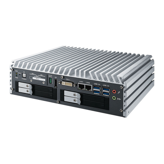
- Page 1 USER USER IVH-7700 Manual Manual Quad Core Intel ® Core™ i7/ i5/ i3 Fanless In-Vehicle System High Performance, Rugged, Extended Temp, Power Protection 1.1.0 Edition 20151006...
- Page 2 Record of Revision Version Date Page Description Remark 07/23/2015 Preliminary Release 08/10/2015 Official Release 10/06/2015 Update Release...
- Page 3 Declaimer This manual is released by Vecow Co., Ltd. for reference purpose only. All product offerings and specifications are subject to change without prior notice. It does not represent commitment of Vecow Co., Ltd. Vecow shall not be liable for direct, indirect, special, incidental, or consequential damages arising out of the use of the product or documentation, nor for any infringements upon the rights of third parties, which may result from such use.
- Page 4 Order Information Part Number Description ® IVH-7700-QRD IVH-7700 Intel Quad Core™ In-Vehicle Fanless Embedded System, 6 GbE LAN with 4 RJ45 PoE , 4 Front-access SSD, 4 COM, 11 USB, 4 SIM, 16 Isolated DIO, 16 GPIO ® IVH-7700-QRDM IVH-7700 Intel Quad Core™...
-
Page 5: Table Of Contents
1.4 Supported CPU List 1.5 Mechanical Dimension 1.5.1 Dimensions of IVH-7700-QRD 1.5.2 Dimensions of IVH-7700-QRDM CHAPTER 2 GETTING TO KNOW YOUR IVH-7700 2.1 Packing List 2.2 Front Panel I/O Functions 2.3 Rear Panel I/O and Functions 2.4 Main Board Expansion Connectors 2.5 Main Board Jumper Settings... - Page 6 CHAPTER 4 BIOS AND DRIVER SETTING 4.1 BIOS Settings 4.2 Main Menu 4.3 Advanced Function 4.4 Chipset Function 4.5 Boot Function APPENDIX A : ISOLATED DIO GUIDE APPENDIX B : GPIO and WDT Functions APPENDIX C : Power Consumption APPENDIX D : UPS Installation APPENDIX E : Ignition Control APPENDIX F : RAID Installation Guide...
-
Page 7: Chapter 1 General Introduction
6V to 78V wide range power input, smart surge protection up to 200V, configurable ignition power control, UPS supported, 16 isolated DIO, fanless design and -25°C to 70°C operating temperature, Vecow IVH-7700 Series In-Vehicle Fanless Embedded System delivers excellent system performance for in-vehicle mission critical applications. 1.2 Features ®... -
Page 8: Product Specification
1.3 Product Specification 1.3.1 Specifications of IVH-7700-QRD System ® Processor Intel Core™ i7-3610QE/ i5-3610ME/ i3-3120ME ® Chipset Intel QM77 BIOS IT8783 Memory • DDR3 1066/1333/1600 MHz or DDR3L 1066/1333MHz • Up to 16GB • 2 204-pin SO-DIMM Socket I/O Interface Serial •... - Page 9 Audio Audio Codec Realtek ALC892, 5.1 Channel HD Audio Audio Interface 1 Mic-in, 1 Line-out Ethernet ® LAN 1 Intel 82579LM Gigabit LAN supports iAMT 8.0 ® LAN 2 Intel I210 Gigabit LAN ® LAN 3 Gigabit IEEE 802.3at (25.5W/48V) PoE+ by Intel I210 ®...
-
Page 10: Specifications Of Ivh-7700-Qrdm
• IEC 60068-2-27 • SSD : 50G @ Wallmount, Half-sine, 11ms Vibration • IEC 60068-2-64 • SSD : 5Grms, 5Hz to 500Hz, 3 Axis CE, FCC, EN 50155, EN 50121-3-2 1.3.2 Specifications of IVH-7700-QRDM System ® Processor Intel Core™ i7-3610QE/ i5-3610ME/ i3-3120ME ®... - Page 11 Graphics ® Chipset Intel HD Graphics 4000 Display Memory Shared Memory, up to 1.7GB Interface Triple Independent Display : • DVI-I : Up to 1920 x 1200 • DisplayPort : Up to 2560 x 1600 • LVDS : Dual channel 24-bit, up to 1920 x 1200 Storage SATA •...
- Page 12 95% at 70°C Shock • IEC 60068-2-27 • SSD : 50G @ Wallmount, Half-sine, 11ms Vibration • IEC 60068-2-64 • SSD : 5Grms, 5Hz to 500Hz, 3 Axis CE, FCC, EN 50155, EN 50121-3-2 ©Vecow IVH-7700 User Manual GENERAL INTRODUCTION...
-
Page 13: Supported Cpu List
1.4 Supported CPU List Processor No. Cache Max. Frequency Embedded i7-3940XM Up to 3.90GHz i7-3920XM Up to 3.80GHz i7-3840QM Up to 3.80GHz i7-3820QM Up to 3.70GHz i7-3740QM Up to 3.7GHz i7-3720QM Up to 3.60GHz i7-3630QM Up to 3.40GHz i7-3612QE Up to 3.10GHz i7-3610QM Up to 3.30GHz i7-3610QE... -
Page 14: Mechanical Dimension
1.5 Mechanical Dimension 1.5.1 Dimensions of IVH-7700-QRD 260,0 (10.2”) 215,0 (8.5”) 260,0 (10.2”) 215,0 (8.5”) 79,1 (3.1”) 260,0 (10.2”) 215,0 (8.5”) Unit: mm (inch) 1.5.2 Dimensions of IVH-7700-QRDM 260,0 (10.2”) 215,0 (8.5”) 260,0 (10.2”) 215,0 (8.5”) 79,1 (3.1”) 260,0 (10.2”) 215,0 (8.5”) -
Page 15: Chapter 2 Getting To Know Your Ivh-7700
2.1 Packing List Item Description IVH-7700 In-Vehicle Fanless Embedded System (According to the configuration you order, the IVH-7700 series may contain SSD/HDD and DDR3L SO-DIMM. Please verify these items if necessary.) Accessory box, which contains ● Vecow Drivers & Utilities DVD ●... -
Page 16: Front Panel I/O Functions
CFast POWER It is a hardware reset switch. Use this switch to reset the system without power off the IVH-7700. Press the Reset Switch for a few seconds, then reset will be enabled. ©Vecow IVH-7700 User Manual GETTING TO KNOW YOUR IVH-7700... - Page 17 S3, S5 Suspend to RAM, System off with standby power To power on IVH-7700, press the power button and then the blue LED is lightened. To power off IVH-7700, you can either command shutdown by OS operation, or just simply press the power button.
- Page 18 It is implemented by a SATA II Port from QM77 PCH. Be sure to disconnect the power source and unscrew the CFast socket cover before installing a CFast card. The IVH-7700 does not support the CFast hot swap and PnP (Plug and Play) functions. It is necessary to remove power source first before inserting or removing the CFast card.
- Page 19 1920 x 1200 resolution and output mode supports up to 1920 x 1200 resolution. The DVI mode is automatically selected according to the display device connected. You will need a DVI-I cable when connecting to a display device. GETTING TO KNOW YOUR IVH-7700...
- Page 20 There are 4 USB 3.0 connections available supporting up to 5GB per second data rate in the front side of IVH-7700. It also compliant with the requirements of SuperSpeed (SS), High Speed (HS), Full Speed (FS) and Low Speed (LS).
- Page 21 CN44 (SIM 1) CN42 CN31 (SIM 2) CN14 CN45 (SIM 3) CN46 (SIM 4) Note: The SIM card sockets do not support hot-plug. Please make sure to unplug the system power before inserting the SIM card(s). GETTING TO KNOW YOUR IVH-7700...
- Page 22 POWER There are 2 8-pin RJ-45 jacks supporting 10/100/1000 Mbps Ethernet ® connections in the front side of IVH-7700. LAN 1 is powered by Intel 82579LM Ethernet engine; LAN 2 is powered by Intel I210 Ethernet engine. When both LAN 1 and LAN 2 work in normal status, iAMT 8.0 function is enabled.
- Page 23 USB 3.0 WWAN SIM 2 RESET CFast POWER There are 4 front-access 2.5” SSD/ HDD trays in the front side of IVH-7700. Just trigger to open the SSD/ HDD tray, up to 8TB is available. GETTING TO KNOW YOUR IVH-7700...
-
Page 24: Rear Panel I/O And Functions
PIN 1 ~ 8 PIN 11 ~ 18 IVH-7700 supports 6V to 78V DC power input by terminal block in the rear side. In normal power operation, power LED lightens in solid green. Onboard LTC4364 supports up to 200V surge protection. - Page 25 OUTPUT 4 SIO_GPO24 INPUT 5 SIO_GPI55 OUTPUT 5 SIO_GPO25 INPUT 6 SIO_GPI56 OUTPUT 6 SIO_GPO26 INPUT 7 SIO_GPI57 OUTPUT 7 SIO_GPO27 DI_COM ----------- N.C. ----------- ----------- External OUTPUT 0 SIO_GPO20 24~78VDC ----------- OUTPUT 1 SIO_GPO21 Input GETTING TO KNOW YOUR IVH-7700...
- Page 26 GPI SOURCE Mode Digital GPI input signal circuit in SOURCE mode (PNP) is illustrated as follow : GPO SINK Mode Digital GPO output circuit in SINK mode (NPN) is illustrated as follow : ©Vecow IVH-7700 User Manual GETTING TO KNOW YOUR IVH-7700...
- Page 27 Serial Pin No. RS-232 RS-422 RS-422 RS-485 Port (5-wire) (9-wire) (3-wire) TXD- TXD- DATA- TXD+ TXD+ DATA+ RXD+ RXD+ ----------- RXD- RXD- ----------- ----------- RTS- ----------- ----------- RTS+ ----------- ----------- CTS+ ----------- ----------- CTS- ----------- GETTING TO KNOW YOUR IVH-7700...
- Page 28 Port (5-wire) (9-wire) (3-wire) ----------- ----------- ----------- ----------- ----------- ----------- ----------- ----------- ----------- ----------- ----------- ----------- ----------- ----------- ----------- ----------- ----------- ----------- ----------- ----------- ----------- ----------- ----------- ----------- ----------- ----------- ----------- ©Vecow IVH-7700 User Manual GETTING TO KNOW YOUR IVH-7700...
- Page 29 2.3.6 PoE (Power over Ethernet) Ports PIN 1 ~ 8 PIN 11 ~ 18 There are 4 RJ45 connectors in the rear side of IVH-7700. They support IEEE 802.3at (PoE ) Power over Ethernet (PoE) connection delivering up to 25.5W/ 48V per port and 1000BASE-T gigabit data signals over standard Ethernet Cat 5/ Cat 6 cable.
- Page 30 PIN 1 ~ 8 PIN 11 ~ 18 There are 4 USB 3.0 connections available in the rear side of IVH-7700. Each USB 3.0 channel is powered by independent USB 3.0 controller supporting up to 5GB per second data rate. It also compliant with the requirements of SuperSpeed (SS), High Speed (HS), Full Speed (FS) and Low Speed (LS).
-
Page 31: Main Board Expansion Connectors
2.4 Main Board Expansion Connectors 2.4.1 Front View of IVH-7700 Main Board With Connector Location CN32 FAN1 CN37 CN33 CN23 CN36 CN18 CN27 CN19 CN26 CN35 CN28 CN20 CN24 CN42 CN21 CN25 Battery J4 J5 BIOS CN44 CN14 CN43 CN31... - Page 32 2.4.2 Rear View of IVH-7700 Main Board With Connector Location LTM-2883 IT-8783F PLX-8608 CPU Socket CN46 CN45 ©Vecow IVH-7700 User Manual GETTING TO KNOW YOUR IVH-7700...
- Page 33 The pinouts of Miscellaneous port are listed in following table: Group Pin No. Description HD_LED+ HDD LED HD_LED- FP_RST_BTN_N RESET BUTTON PWR_LED+ POWER LED PWR_LED_N FP_PWR_BTN_N POWER BUTTON GETTING TO KNOW YOUR IVH-7700...
- Page 34 2.4.4 CN35, CN28 : J6 LVDS CN35 CN28 IVH-7700 supports dual-channel 24-bit LVDS display, up to 1366 x 768 pixels resolution. The pin assignments of CN35 and CN28 are listed in the following table: Definition Pin No. CN28 Channel A...
- Page 35 The LCD inverter is connected to J6 via a JST 7-pin, 2.5mm connector providing +5V/ +12V power to LCD display. The pin assignments are listed in the following table: Pin No. Definition +12V +12V LBKLT_CTL LBKLT_EN GETTING TO KNOW YOUR IVH-7700...
- Page 36 CN21 CN25 There are 2 onboard high performance Serial ATA III (SATA III) on IVH-7700. It supports higher storage capacity with less cabling effort and smaller required space. The pin assignments of CN21 and CN25 are listed in the following table: Pin No.
- Page 37 CN20 CN24 There are 2 onboard high performance Serial ATA II (SATA II) on IVH-7700. It supports higher storage capacity with less cabling effort and smaller required space. The pin assignments of CN20 and CN24 are listed in the following table: Pin No.
- Page 38 CN32 CN33 The IVH-7700 also equip with 2 SATA power connector. It supports 5V (Up to 2A) and 12V (Up to 1A) current to the hard drive or SSD. The pin assignments of CN32 and CN33 are listed in the following table: Pin No.
- Page 39 2.4.8 J4, J5 : Internal Dual Port USB J4 J5 The IVH-7700 main board provides up to 2 expansion USB ports using plug- and-play for Dongle Key or LCD touch Panel. The USB interface supports 480 Mbps transfer rate which comply with high speed USB specification Rev. 2.0, and are fuse protected.
- Page 40 1. When a Mini PCIe device is inserted, its Pin 43 forces the respective pin on the socket to ground, or logic 0. IVH-7700 SW5 Pin 43 status is designed for switching mSATA drive and Mini PCIe devices.
- Page 41 Reserved Status Reserved +3.3Vaux Reserved +3.3Vaux USB_D+ USB_D- PETp0 PETn0 SMB_DATA SMB_CLK +1.5V PERp0 PERn0 +3.3Vaux PERST# Reserved reserved Reserved Mechanical Key Reserved REFCLK+ Reserved REFCLK- Reserved Reserved CLKREQ# Reserved Reserved 1.5V Reserved WAKE# 3.3Vaux GETTING TO KNOW YOUR IVH-7700...
- Page 42 The pin assignments of CN7, CN14 and CN42 are listed in the following table: Pin No. Signal Name Pin No. Signal Name Reserved +3.3Vaux Reserved Reserved +1.5V Reserved Reserved Reserved +3.3Vaux Reserved +3.3Vaux USB_D+ USB_D- PETp0 PETn0 SMB_DATA SMB_CLK +1.5V ©Vecow IVH-7700 User Manual GETTING TO KNOW YOUR IVH-7700...
- Page 43 PERp0 PERn0 +3.3Vaux PERST# Reserved reserved Reserved Mechanical Key Reserved REFCLK+ Reserved REFCLK- Reserved Reserved CLKREQ# Reserved Reserved 1.5V Reserved WAKE# 3.3Vaux GETTING TO KNOW YOUR IVH-7700...
- Page 44 2.4.11 CN23 : GPIO CN23 The IVH-7700 offers 16 programmable I/O within TTL 5V tolerance. If the GPIO is logic high, it indicates that the mapping SIO GPIO pin is logic high level. If the GPIO is logic low, it indicates that the mapping SIO GPIO pin is logic low level.
- Page 45 2.4.12 FAN 1 FAN1 Fan power connector supports for additional thermal requirements. The pin assignments of FAN 1 are listed in the following table: Pin No. Function +12V (1.5A max) Fan speed sensor GETTING TO KNOW YOUR IVH-7700...
- Page 46 The pin assignments of CN4 are listed in the following table: Pin No. Function Pin No. Function LAN3_MDI3_P 3.3V LAN3_MDI3_N VEE_LAN3 LAN3_MDI2_P VEE_LAN3 LAN3_MDI2_N VEE_LAN3 GND_POE LAN3_MDI1_P GND_POE LAN3_MDI1_N GND_POE LAN3_MDI0_P 1.5V_LAN3 LAN3_MDI0_N LAN3_L100# LAN3_L1000# LAN3_ACTLED# LAN4_MDI3_P LAN4_MDI3_N VEE_LAN4 ©Vecow IVH-7700 User Manual GETTING TO KNOW YOUR IVH-7700...
- Page 47 LAN4_MDI1_N 1.5V_LAN4 LAN4_MDI0_P LAN4_L100# LAN4_MDI0_N LAN4_L1000# LAN4_ACTLED# LAN5_MDI3_P VEE_LAN5 LAN5_MDI3_N VEE_LAN5 VEE_LAN5 LAN5_MDI2_P GND_POE LAN5_MDI2_N GND_POE GND_POE LAN5_MDI1_P LAN5_MDI1_N 1.5V_LAN5 LAN5_L100# LAN5_MDI0_P LAN5_L1000# LAN5_MDI0_N LAN5_ACTLED# VEE_LAN6 LAN6_MDI3_P VEE_LAN6 LAN6_MDI3_N VEE_LAN6 GND_POE LAN6_MDI2_P GND_POE LAN6_MDI2_N GND_POE GETTING TO KNOW YOUR IVH-7700...
- Page 48 2.4.14 Battery Battery The IVH-7700’s real-time clock is powered by a lithium battery. It is Equipped with Panasonic BR2032 190mAh lithium battery. It is recommended that you not replace the lithium battery on your own. If the battery needs to be changed, please contact Vecow RMA Service Team.
- Page 49 ME Clear Setting Clear ME * Normal SW1-3 SW1-4 ATX / AT Power Mode AT MODE * ATX MODE SW1-5 Front USB Power Selection * +5V Main Power (No Wake-up Function) +5V Standy Power (Supports Wake-up Function) GETTING TO KNOW YOUR IVH-7700...
- Page 50 2.4.16 SW4 : COM 1, COM 2 RS-422/485 Receiver Termination ON/OFF SW4-1 COM1 RS-422/485 Receiver Termination * Enabled Disabled SW4-2 COM1 RS-422/485 Receiver Termination * Enabled Disabled ©Vecow IVH-7700 User Manual GETTING TO KNOW YOUR IVH-7700...
- Page 51 Rear USB #1 Current Limitation (CN11) 1.5A * 0.9A SW2-2 Rear USB #2 Current Limitation (CN13) 1.5A * 0.9A SW2-3 Rear USB #3 Current Limitation (CN15) 1.5A * 0.9A SW2-4 Rear USB #4 Current Limitation (CN16) 1.5A * 0.9A GETTING TO KNOW YOUR IVH-7700...
- Page 52 SCLOCK SDATA_OUT0 SLOAD SDATA_OUT1 2.4.19 J1 : LAN2 I210 SDP The pin assignments of J1 are listed in the following table: Pin No. Function Pin No. Function LAN2_SDP0 LAN2_SDP1 LAN2_SDP2 LAN2_SDP3 ©Vecow IVH-7700 User Manual GETTING TO KNOW YOUR IVH-7700...
- Page 53 The pin assignments of J3 are listed in the following table: Pin No. Function Pin No. Function MCU_RST# 3.3V_MCU MCU_PRG 2.4.21 CN36 : +V12_SB Output CN36 The pin assignments of CN36 are listed in the following table: Pin No. Function Pin No. Function +V12_SB +V12_SB GETTING TO KNOW YOUR IVH-7700...
- Page 54 You can also use these USB hosts to connect to a keyboard or a mouse. The pin assignments of CN37 are listed in the following table: Pin No. Function Pin No. Function USB13- USB13+ ©Vecow IVH-7700 User Manual GETTING TO KNOW YOUR IVH-7700...
-
Page 55: Main Board Jumper Settings
2.5.1 Front View of IVH-7700 Main Board With Jumper Location The figure below is the top view of the IVH-7700 main board which is the main board used in the IVH-7700 Series system. It shows the location of the jumpers. - Page 56 JP1 provides LVDS voltage selection function, closing Pin 1, 2 is for 3.3V LVDS power input; closing Pin 2, 3 is for 5V LVDS power input. Pin No. Function +3.3V (Default) ©Vecow IVH-7700 User Manual GETTING TO KNOW YOUR IVH-7700...
- Page 57 Pin 9 Function * RI RI/ +5V/ +12V +12V COM2 Pin 9 Function * RI RI/ +5V/ +12V +12V COM3 Pin 9 Function * RI RI/ +5V/ +12V +12V COM4 Pin 9 Function * RI GETTING TO KNOW YOUR IVH-7700...
-
Page 58: Ignition Control
PIN 1 ~ 8 PIN 11 ~ 18 2.6.1 Adjust Ignition Control Modes IVH-7700 series provides 16 modes of different power on/ off delay periods adjustable via rotary switch. The default rotary switch is set to 0 in ATX/ AT power mode. - Page 59 : Ground of DC power input (Car battery -/GND line to GND) : Ignition signal input (ACC power of vehicle) For testing purpose, you can refer to the picture blow to simulate ignition signal input controlled by a latching switch. GETTING TO KNOW YOUR IVH-7700...
- Page 60 1. DC power source and IGN share the same ground. 2. IVH-7700 supports 6V~78V wide range DC power input in ATX/AT mode. In Ignition mode, the input voltage is fixed to 12V/24V/48V for car battery scenario. 3. For proper ignition control, the power button setting should be “Power Down”...
-
Page 61: Chapter 3 System Setup
3.1 How to Open Your IVH-7700-QRD/ IVH-7700- QRDM Step 1 Remove 6 pcs KHS#6-32 screws (circled in red) and 2 pcs DVI-I #4-40 screws (circled in yellow) in the front side. (IVH-7700-QRD/ IVH-7700-QRDM) Step 2 Take off the front panel. (IVH-7700-QRD/ IVH-7700-QRDM) - Page 62 Step 3 Remove 4 pcs F#6-32x6 screws (circled in red) in the bottom side. (IVH-7700-QRD/ IVH-7700-QRDM) Step 4 Remove 1 pcs KHS#6-32 screw (circled in red) on the rear panel. (IVH-7700-QRD/ IVH-7700-QRDM) ©Vecow IVH-7700 User Manual HARDWARE INSTALLATION...
- Page 63 Step 5 Turn over IVH-7700-QRD/ IVH-7700-QRDM to keep the bottom side up. Take off the lower cover slowly and carefully. (IVH-7700- QRD/ IVH-7700-QRDM) Step 6 Unplug 4 pcs 7-pin SATA and 2 pcs power connectors. (IVH-7700-QRD/ IVH-7700-QRDM) HARDWARE INSTALLATION...
- Page 64 Step 7 Unplug 4 pcs DB9 connectors on the main board. (IVH-7700-QRD/ IVH-7700-QRDM) ©Vecow IVH-7700 User Manual HARDWARE INSTALLATION...
- Page 65 Step 8 Remove 5 pcs KHS#6-32x6 screws (circled in red) on rear panel. (IVH-7700-QRD/ IVH-7700-QRDM) Step 9 Take off the rear panel. (IVH-7700-QRD/ IVH-7700-QRDM) HARDWARE INSTALLATION...
-
Page 66: Installing Ddr3L/ Ddr3 So-Dimm Modules
3.2 Installing DDR3L/ DDR3 SO-DIMM Modules Step 1 Install DDR3L/ DDR3 RAM module into SO-DIMM slot. (IVH-7700-QRD/ IVH-7700-QRDM) Step 2 Make sure the RAM module is locked by the memory slot. (IVH-7700-QRD/ IVH-7700-QRDM) ©Vecow IVH-7700 User Manual HARDWARE INSTALLATION... -
Page 67: Installing Mini Pcie Card
3.3 Installing Mini PCIe Card Step 1 Install Mini PCIe card into the Mini PCIe socket. (IVH-7700-QRD/ IVH-7700-QRDM) Step 2 Fasten 2 pcs M2.5 screws. (IVH-7700-QRD/ IVH-7700-QRDM) HARDWARE INSTALLATION... -
Page 68: Installing Cpu
3.4 Installing CPU 3.4.1 IVH-7700-QRD Step 1 Remove IVH-7700 main board from upper case Step 2 Remove 6 pcs M3x11 springs (circled in yellow) and 8 pcs M3x6 screws (circled in red) on the main board. Step 3 Get the main board from upper case. - Page 69 Step 5 Do check if CPU direction fits the CPU socket. Step 6 Install CPU and lock the socket. HARDWARE INSTALLATION...
- Page 70 3.4.2 IVH-7700-QRDM Step 1 Remove IVH-7700 main board from upper case. Step 2 Remove 2 pcs M3x6 screws (circled in red) on M12 module. Step 3 Remove 6 pcs M3x11 springs (circled in yellow), 6 pcs M3x6 screws (circled in red) and 2 pcs M3x16 copper tubes (marked in green) on the main board.
- Page 71 Step 5 Turn over the main board and find CPU socket. Step 6 Do check if CPU direction fits the CPU socket. Step 7 Install CPU and lock the socket. HARDWARE INSTALLATION...
-
Page 72: Installing Antenna Cable
3.5 Installing Antenna Cable Step 1 Check Antenna cable and washers. Step 2 Remove the rubber cork on rear panel. (Pick up the location you want.) ©Vecow IVH-7700 User Manual HARDWARE INSTALLATION... - Page 73 Step 3 Put Antenna cable connector into the hole on rear panel. Step 4 Fasten the washer 1, washer 2 and washer 3 on Antenna cable connector. Step 5 Antenna cable is installed ready. HARDWARE INSTALLATION...
-
Page 74: Installing Cfast Card And Sim Card
3.6 Installing CFast Card and SIM Card Step 1 Remove 2 pcs F-M3x4 screws on CFast Card and SIM Card cover at front panel. Step 2 Remove CFast Card and SIM Card cover from front panel. ©Vecow IVH-7700 User Manual HARDWARE INSTALLATION... - Page 75 Step 3 Insert CFast card and push to lock. Step 4 Before Inserting SIM card, make sure the system power is not working. Step 5 Insert SIM card and push to lock. Step 6 SIM card and CFast card are installed ready. HARDWARE INSTALLATION...
-
Page 76: Installing Ssd/Hdd
3.7 Installing SSD/HDD Step 1 Trigger and open SSD/HDD tray. Step 2 Insert 2.5” SSD/HDD in the tray. ©Vecow IVH-7700 User Manual HARDWARE INSTALLATION... - Page 77 Step 3 Push back and close the SSD/HDD tray. Step 4 Lock the SSD/HDD tray with key. HARDWARE INSTALLATION...
-
Page 78: Mounting Ivh-7700
3.8 Mounting IVH-7700 Step 1 Ensure the screw holes on the right and left side of upper case match the ones on IVH-7700 wall mount bracket. Step 2 Fasten 4pcs KHS#6-32 screws. ©Vecow IVH-7700 User Manual HARDWARE INSTALLATION... - Page 79 BIOS AND DRIVER SETTING 4.1 BIOS Settings 4.1.1 BIOS Setup The board uses UEFI BIOS that is use Serial Peripheral Interface (SPI) Flash. The SPI Flash contains the BIOS Setup program, POST, the PCI auto- configuration utility, LAN, EEPROM information, and Serial port support. The BIOS setup program is accessed by pressing the <Del>...
- Page 80 Press “TAB” key to switch sub-items of value .Then press “ +” key or “-“ key number key for modify value. In this page, you could make sure you CPU type and DRAM type that you are install into this system. BIOS AND DRIVER SETTING ©Vecow IVH-7700 User Manual...
- Page 81 4.3 Advanced Function 4.3.1 ACPI Setting Phoenix SecureCore(tm) Setup Utility Main Advanced Chipset Boot Security Save & Exit Item Specific Help ACPI Settings Enable ACPI Auto Configuration [Disabled] Enable Hibernation [Enabled] Figure 4-3-1: ACPI Setting setup screen Enable ACPI Auto Configuration This system support ACPI function as auto process.
- Page 82 Enables or Disables BIOS support for security device. O.S. will now show Security Device. TCG EFT protocol and INT1A interface will not be available. Current Status Information Show as below option : • SUPPORT TURNED OFF • SUPPORT TURNED ON BIOS AND DRIVER SETTING ©Vecow IVH-7700 User Manual...
- Page 83 4.3.3 CPU Configuration Phoenix SecureCore(tm) Setup Utility Main Advanced Chipset Boot Security Save & Exit Item Specific Help CPU Configuration Intel (R) Core (TM) i7-3610QE CPU @ 2.30GHz Inter Virtualization Technology [Disable] Figure 4-3-3 : CPU Configuration Setup screen Intel Virtualization Technology This for for Virtualization Application or platform usage, when enabled, a VMM can utilize the additional hardware capabilities provided by Vanderpool Technology.
- Page 84 Pick up the SATA Mode you need. There are 3 options to choose [IDE]/ [AHCI]/ [RAID] Mode. For the RAID mode setup, please go to Appendix F for detail information. Serial Port 0 to 5 There are 6 SATA ports available for SATA device connection. BIOS AND DRIVER SETTING ©Vecow IVH-7700 User Manual...
- Page 85 4.3.5 AMT Configuration Phoenix SecureCore(tm) Setup Utility Main Advanced Chipset Boot Security Save & Exit Item Specific Help Intel AMT [Enabled] BIOS Hotkey Pressed [Disabled] MEBx Selection Screen [Disabled] Figure 4-3-5 : AMT Setup screen Intel AMT Enables or Disables Intel(R) Active Management Technology BIOS extension. This option just controls the BIOS extension executes.
- Page 86 There are 4 options as follow : • IO=3F8h; IRQ=4; • IO=2F8h; IRQ=3; • IO=3E8h; IRQ=10; • IO=2E8h; IRQ=11; Interface Mode There are 3 options as follow : • RS-232 Mode • RS-422 Mode • RS-485 Mode BIOS AND DRIVER SETTING ©Vecow IVH-7700 User Manual...
- Page 87 4.3.7 Serial Port 2 Configuration Advanced → IT8783F Super IO Configuration → Serial Port Phoenix SecureCore(tm) Setup Utility Main Advanced Chipset Boot Security Save & Exit Item Specific Help Serial Port 2 Configuration Serial Port [Enabled] Device Settings IO=2F8h; IRQ=3; Change Settings [IO=2F8h;...
- Page 88 Current IO address and interrupt resource of Serial Port. Change Settings Select another device setting. There are 6 options as follow : • IO=3F8h; IRQ=4; • IO=2F8h; IRQ=3; • IO=3E8h; IRQ=10; • IO=2E8h; IRQ=11; • IO=2F0h; IRQ=6; • IO=2E0h; IRQ=7; BIOS AND DRIVER SETTING ©Vecow IVH-7700 User Manual...
- Page 89 4.3.9 Serial Port 4 Configuration Advanced → IT8783F Super IO Configuration → Serial Port Phoenix SecureCore(tm) Setup Utility Main Advanced Chipset Boot Security Save & Exit Item Specific Help Serial Port 4 Configuration Serial Port [Enabled] Device Settings IO=3F8h; IRQ=4; Change Settings [IO=3F8h;...
- Page 90 [Power Off] : When plug-in the power source, system will keep on SB mode. [Power On] : When plug-in the power source, system will auto booting . [Last State] : When plug-in the power source, system will keep on last power status. BIOS AND DRIVER SETTING ©Vecow IVH-7700 User Manual...
- Page 91 4.5 Boot Function 4.5.1 Boot Option Phoenix SecureCore(tm) Setup Utility Main Advanced Chipset Boot Security Save & Exit Item Specific Help Boot Configuration Boot option #1 [SATA PS:Device Name ] Boot option #2 [SATA PS:Device Name ] Figure 4-5-1 : Boot Setup screen Boot option When you press “Enter”, you can select which device you would like to boot.
- Page 92 GPIO Output 0 EXT_IN1 GPIO Input 1 EXT_OUT1 GPIO Output 1 EXT_IN2 GPIO Input 2 EXT_OUT2 GPIO Output 2 EXT_IN3 GPIO Input 3 EXT_OUT3 GPIO Output 3 EXT_IN4 GPIO Input 4 EXT_OUT4 GPIO Output 4 Appendix A ©Vecow IVH-7700 User Manual...
- Page 93 EXT_IN5 GPIO Input 5 EXT_OUT5 GPIO Output 5 EXT_IN6 GPIO Input 6 EXT_OUT6 GPIO Output 6 EXT_IN7 GPIO Input 7 EXT_OUT7 GPIO Output 7 DI_COM GPIO COM Reserved EGND GPIO GND E24V External 24V DC Signal Circuit of Input NPN Digital GPIO input signal circuit in SINK mode (NPN) is illustrated as follow.
- Page 94 Supports WinXP 32-bit and Windows 7 32-bit. Please do make sure your OS version before installing. For WinXP : Please select “add new hardware” manually on Control panel For Windows 7 : Please select “Add legacy hardware” on device management Appendix A ©Vecow IVH-7700 User Manual...
- Page 95 APPENDIX B : GPIO and WDT Functions B.1 Function Description The WDT are using internal Super IO function. However, you must entry super I/O configuration mode to set it. Super I/O special address port = 0x2E Super I/O special data port = 0x2F GPIO Logical device is 0x07 B.2 Entry Functions 1.
- Page 96 APPENDIX C : Power Consumption IVH-7700 Power Consumption Testing : IVH-7700 Storage- Aux card MRCAJ5B032GC2CAC00 CFast Storage- Aux card SATA 0 Storage- Power Chroma 62006P-100-25 SATA 1 Source Power Source : Standby Mode DC-in Max Current Max Consumption i7-3610QE 0.224A 02.69W...
- Page 97 Power-on and boot to Win7 64-bit Idle Status : Run 100% CPU usage DC-in CPU usage less 3% Current Consumption Current Consumption i7-3610QE 1.780A 21.36W 3.620A 43.44W i7-3610QE 1.091A 20.73W 2.260A 42.94W i7-3610QE 0.870A 20.88W 1.750A 42.00W i7-3610QE 0.622A 22.39W 1.220A 43.92W i7-3610QE...
- Page 98 Step 1 You need 1pcs new Rear Panel, 1pcs new 3-pin terminal block and 4pcs DB9 cable from your IVH-7700. Step 2 Fix the external connector of new terminal block on the IVH-7700 real panel with 2pcs F-M3x4 screws. Appendix D...
- Page 99 Step 3 Assemble the internal power connector and power cables. Step 4 Fasten the screws to fix power cables on internal power connector. Step 5 Plug the power connector into the power socket on IVH-7700 main board. Appendix D...
- Page 100 Step 6 Plug the internal power connector into the power socket. Step 7 Plugged ready. Step 8 Assemble and fix the rear panel with 5pcs KSH#6-32 screws (circled in red). Appendix D ©Vecow IVH-7700 User Manual...
- Page 101 Step 9 Assemble 4pcs DB9 cables. Step 10 You need a UPS Module and SSD/ HDD bracket of IVH-7700. Step 11 Put the UPS Module into the bracket. Appendix D...
- Page 102 Step 12 Fix the UPS Module on the bracket with 4pcs screws. Step 13 Fix the UPS Module on the inner side of IVH-7700 Lower Cover. Step 14 Fasten 6pcs F-MSx4 screws to fix the UPS Module with bracket. Appendix D...
- Page 103 Step 15 Plug-in the power cable from the main board power socket to UPS Power socket (Circled in Yellow). Plug-in the power cable from the terminal block on the rear panel to UPS Power socket (Circled in Red). Step 16 Power cables plugged ready. Appendix D...
- Page 104 Step 17 Fasten 4pcs F-#6-32 screws to fix IVH-7700 Lower Cover. Step 18 Fasten 1 pcs KSH-#6-32 screw to fix IVH-7700 rear panel. Step 19 Fasten 6 pcs KSH-#6-32 screws to fix IVH-7700 front panel. Appendix D ©Vecow IVH-7700 User Manual...
- Page 105 Step 20 Do remember to fasten 2 pcs #4-40 screws on the front panel to fix DVI-D connector. Note: The external power input goes to UPS, and the UPS provides power to IVH-7700. When Internal UPS is installed, please ensure appropriate voltage/polarity power input to UPS. Appendix D...
- Page 106 //10min case 5:Count_1=20;break; //20min case 6:Count_1=30;break; //30min case 7:Count_1=50;break; //50min case 8:Count_1=1; //1Hr case 9:Count_1=2; //2Hr case 10:Count_1=3; //3Hr case 11:Count_1=6; //6Hr case 12:Count_1=9; //9Hr case 13:Count_1=12; //12Hr case 14:Count_1=15; //15Hr case 15:Count_1=18; //18Hr Appendix E ©Vecow IVH-7700 User Manual...
- Page 107 SATA Model Selection [AHCI] F.2 OS Installation IVH-7700 is featured with 6 SATA, include 4 internal SATA, 1 mSATA and 1 CFast. You can select one of SATA port for OS installation We use CFast card for Windows 7 OS installation as an example.
- Page 108 F.7 To Create RAID Volume on “Rapid Storage Technology” Software IVH-7700 is featured with 4 SATA HDDs for RAID volume, so there are three options for choose on this page. Let’s take RAID 1 as example, please select ”RAID 1”.
- Page 109 F.8 Disk Management : Partition the Disk After RAID 1 volume created, you can see the figure of SATA device allocation. You will find “Volume_0000” in SATA device at BIOS menu. To start Disk Management tool and select “Initialize Disk”. Then add “Logical Device”...
- Page 110 F.9 If One SATA HDD on RAID Volume is Out-of-use After RAID 1 volume created, you can see the figure of SATA device allocation. HDD CAUTION Sign F.10 Recovery and Auto Re-build When Use the SAME RAID HDD Appendix F ©Vecow IVH-7700 User Manual...
- Page 111 F.11 Recovery and Auto Re-build When Use DIFFERENT RAID HDD There is a warning will pop-up to ask you if the disk is not a member of original RAID volume. If you press “Rebuild”, it will replace the broken SATA HDD to the last one SATA HDD of RAID volume.
- Page 112 For further support information, please visit www.vecow.com This document is released for reference purpose only. All product offerings and specifications are subject to change without prior notice. No part of this publication may be reproduced in any form or by any means, electric, photocopying, recording or otherwise, without prior authorization of the publisher.
Need help?
Do you have a question about the IVH-7700 and is the answer not in the manual?
Questions and answers