
Subscribe to Our Youtube Channel
Related Manuals for Wfly RF206S


Summary of Contents for Wfly RF206S
- Page 1 WFLY Shenzhen WFLY Technology Development Co., Ltd (ET Series)8-channel Digital Propor tional R/C System ET08 INSTRUCTION MANUAL WFLY Wechat...
- Page 2 Thank you for using WFLY products! ● Please read this product manual carefully before using this product! ● Please use this product correctly! The model is not a toy, for safety, please don't fly at crowded places! ——Shenzhen WFLY Technology Development Co., Ltd...
- Page 3 CATALOGUE Safety Precautions Symbols Definition Flying Precautions Battery Trainer Port USB Port Before Use Product Features Basic Configuration Each Parts Name Of Transmitter Switch Configuration and Model Types The Travel of Antenna Direction Adjustment Basic Operation Home Interface Introduction Indicator Light of Transmitter Stick Adjustment Left and Right Hand Mode Replacement Method Receiver Instructions...
- Page 4 CATALOGUE System Setting Model Select Model Type Trainer Display User Name Low Battery Sound Language Stick Mode Calibration Data Reset Information Screen Lock Set Linkage Setting Link Telemetry PPM/W.BUS Receiver Output Fail Safe Relay Flight Servo Frequency BUS Servo Setting 180/270°...
- Page 5 CATALOGUE Model Menu\Helicopter Condition Throttle Curve Pitch Curve Throttle Hold Throttle Cut Gyro Governor Swash Model Menu\Airplane Condition AIL Differential Throttle Curve Throttle Hold Throttle Cut Gyro Airbrake ELE to Camber Winglet Elevator V-Tail Flywin Model Menu\Multicopter Condition Throttle Curve Throttle Hold Throttle Cut Stick Alarm...
-
Page 6: Safety Precautions
Flying Precautions Disclaimer & Warning User should be responsible for any consequences caused by using the product. WFLY shall not be liable for any directly or indirectly damage, injury and any legal liability, User shall comply with all guidelines including but not limited to this document. - Page 7 Safety Precautions Battery Lithium polymer battery(Short for LiFe battery),please use the WFLY special charger only.It is important to understand the operating characteristics of Li-Fe batteries. DANGER Long term storage (more than 3 months),storage temperature≤45°C general storage voltage 3.7-3.9v. Failure to follow the proceeding precautions can quickly result in severe, permanent damage to the batteries and possibly result in a fire!
- Page 8 Safety Precautions Trainer Port Mandatory Transmitter trainer port: The trainer port is with 3.5mm audio port output Trainer/Simulator port mode. This suite is without the trainer data line. If USB port you want to use the trainer function, you need to purchase the trainer data line separately! Warning: This port is only used for trainer data transmission.
-
Page 9: Before Use
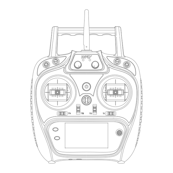
W.BUS: compatible S.BUS Two-way transmission: support Fail-safe: support 180/270° servo: support Receiver port setting: support External voltage detection: DC 0~36V Dimention: 36x20x12mm Basic Configuration ET08 transmitter x1 RF206S receiver x1(include external power detection line x1) Summary manual x1 Transmitter Receiver Summary Manual... - Page 10 Before Use Each Parts Name Of Transmitter Antenna. Carry handle Power LED RF LED SB Switch Block SC Switch Block SA Switch Block SD Switch Block LD Rotary Knob RD Rotary Knob Power Key Hook Stick Stick Trim3 Trim2 Trim4 Trim1 HOME/MON.
- Page 11 Before Use Switch configuration and model types Power LED: Left, power indicator light, red RF LED: Right, RF indicator light, blue. POWER: Click and hold for 3 seconds to open/shut down; SA: Short lever 2 positions (user-defined) SB: Long lever 3 positions (user-defined) SC: Long lever 3 positions (user-defined) SD: Short lever 2 positions (user-defined) LD/RD: Rotary Knob(User-defined)
-
Page 12: Basic Operation
Basic Operation Home Interface Introduction Home Interface 1 Home Interface 2 Introduction and operation 1-20.Timer 1 2.Return data(Receiver voltage) 3.Return data(External battery) 4-5-7-8.Trim monitor, display active trimming status 6."Home2" key, click to enter Home Interface 2 9.Model name: Click to enter model select interface 10.Model type: Click to enter current model type interface 11-21.Timer 2 12.User name, click into user defined name... - Page 13 Basic Operation Indicator Light of Transmitter Status Power LED on Power on Power LED RF LED Power LED off Power off Blue RF LED off Power off , Student or Simulator mode RF LED on Normal Linkage, Trainer or Normal mode RF LED flash Enter link status Stick Adjustment...
- Page 14 If you need components such as bracket 5 (such as the parts needed for assembling double circuit structure!), you can e-mail to WFLY overseas seller to order the spare parts at sales@wflysz.com.
-
Page 15: Receiver Instructions
Otherwise, the receiver will be damaged! Keep the antenna The RF206S is the newest series of high straight performance receiver with 6 PWM channels, the last channel port is PWM/PPM/W.BUS channel (User defined). - Page 16 Basic Operation Receiver and servo connection example - Airplane The figure below shows an example of airplane connection. Please use the actual wing type and tail type for servo connection. CH1/Aileron CH2/Elevator CH3/Throttle CH4/Rudder CH5/Gear CH6/Aux1 Servo connection position (Airplane,refer to stick mode "Mode 1") The table below shows examples of the servo connection positions for the different wing types and tail types(system default settings) Wing Delta wing...
- Page 17 Basic Operation Receiver and servo connection example - Helicopter The figure below shows an example of helicopter connection. Please use the swash type that is actually used for the servo connection. CH1/Aileron CH2/Elevator CH3/Throttle CH4/Rudder CH5/Gyro CH6/Pitch Ser vo connection position (Helicopter,refer to stick mode "mode 1") The table below shows examples of the ser vo connection positions for different swashes.
- Page 18 Basic Operation Receiver and servo connection example - Multicopter The figure below shows the four-rotor multicopter. Please refer to the model manual for specific applications. Motor,electronic speed controller, flight controller, battery, etc. are sold separately. Motor、 ESC (buy seperately) Use 5CH-6CH when using accessories such as camera shutters.
- Page 19 Basic Operation Basic setting sequence of airplane 1. Call of the model Please use the [THROTTLE CUT] function option The ET08 transmitter has 16 built-in models from under [MODEL MENU] to set. After the flame out the factory, and you can use the [MODEL SELECT] function is activated and the corresponding switch under [SYSTEM SETTING] to call up the existing is selected, the throttle position will be adjusted...
- Page 20 Basic Operation Basic setting sequence of the helicopter 1. Model addition and invocation Please refer to the first part of the previous The swash calibration (except H-1 mode) can section "Basic Operation - Basic Settings of calibrate the swash motion by the correction mixing Airplane and Glider”...
- Page 21 Basic Operation Basic setting sequence of the helicopter positive and negative pitch directions. For example, 9. Gyro Sensitivity Adjustment and Mode from -7 to +12°. Switching In the [GYRO] mixing function under [MODEL 6. Throttle Hold Setting MENU], you can adjust the gyro sensitivity or mode From the [MODEL MENU] , call the [THROTTLE switching for each condition or switch position.
-
Page 22: System Setting
SYSTEM SETTING MODEL SELECT Interface path: HOME/MON.→ [SYSTEM SETTING] → [MODEL SELECT] The ET08 can store 16 sets of model data and flexibly edit and process the information of data set. *Example of model sending function (Requires two same types and same firmware versions remote controllers ,and with RF open): Type Signs... -
Page 23: Model Type
SYSTEM SETTING MODEL TYPE Interface path: HOME/MON. → [SYSTEM - Wing: 1 aileron, 2 ailerons, delta wing SETTING] → [MODEL TYPE] - Tail: Normal, V-tail, Ailvator; normal, winglet (delta wing). Airplanes are available in 3 main wing types and 3 tail types. - Page 24 SYSTEM SETTING TRAINER Interface Path: HOME/MON. → [SYSTEM SETTING] → [TRAINER] Trainers can assist students in learning flight skills and improving flight levels based on their flight experience and operational level. A special trainer line (sold separately) is required between the trainer and the trainer to connect.
- Page 25 SYSTEM SETTING SYSTEM SETTING DISPLAY Interface Path: HOME/MON. → [SYSTEM SETTING] → [DISPLAY] Adjust the brightness of the display backlight, the shutdown time, and the lock screen time to adapt to different environments and energy saving. Contrast: sharpness adjustment. Backlight: brightness value. Backlight time: system backlight time! Automatic lock screen time: lock screen after touching the screen without any operation.
- Page 26 SYSTEM SETTING USER NAME Interface path: HOME/MON.→ [SYSTEM SETTING] → [USER NAME] The model name can be user-defined.
-
Page 27: Low Battery
SYSTEM SETTING LOW BATTERY Interface path: HOME/MON. → [SYSTEM SETTING] → [LOW BATTERY] By setting the alarm trigger value, an alarm is given at low voltage. Avoid accidents caused by long-term operation of the control system under low voltage conditions. (beep-beep-beep) Set battery voltage alarm value.(beep beep beep-beep beep beep-beep beep beep- beep beep beep beep beep-... - Page 28 SYSTEM SETTING SOUND Interface path: HOME/MON.→ [SYSTEM SETTING] → [SOUND] The sound helps the flight process to notice various anomalies or planned audible prompts. WARNING: Voltage alarm prompt TRIM:Trim operate sound prompt Timer:On or off timer sound prompt Other:Button, knob over the middle point, etc To ensure safe operation, be WARNING sure to turn on the Sound!
- Page 29 SYSTEM SETTING LANGUAGE Interface path: HOME/MON. → [SYSTEM SETTING] → [LANGUAGE] Select the language displayed on the interface, ET08 provides Chinese and English display.
-
Page 30: Stick Mode
SYSTEM SETTING STICK MODE Interface path: HOME/MON. → [SYSTEM SETTING] → [STICK MODE] Provides 4 operating mode options, in addition to the [Function] user defied the mode. Click "OK" to switch modes Change the stick mode, which NOTICE notice involves the [FUNCTION] content. - Page 31 SYSTEM SETTING CALIBRATION Interface path: HOME/MON. → [SYSTEM SETTING] → [CALIBRATION] The stick has been calibrated at the factory. If the center position of the stick changes,you need to use this function to calibrate the stick. System security: Calibration DANGER performed under the connection state of the receiver may cause wrong operation,must disconnect model connection!
-
Page 32: Data Reset
SYSTEM SETTING DATA RESET Interface path: HOME/MON.→ [SSYTEM SETTING] → [DATA RESET] Reset the transmitter's selected parameter settings. The “ Factory Reset” operation is with large amount of data, please be patient when performing this operation. This function will clear the exist NOTICE model data! All settings under (MODEL MENU) would be reset to... - Page 33 Interface path: HOME/MON. → [SYSTEM SETTING] → [INFORMATION] Displays system version information and system upgrade entries. There is also the Official WeChat of WFLY ,which uses WeChat to scan and add attention. Send "ET08 upgrade package", you can view or download related information. Upgrade...
- Page 34 SYSTEM SETTING SCREEN LOCK SET Interface path: HOME/MON. → [SYSTEM SETTING] → [SCREEN LOCK SET] Set the enable condition of "5-way key/CURSOR", "menu/exit" and "trim" buttons in the lock screen state. Press and hold "EXIT/LOCK"key to operate screen lock and unlock. 5-way key/cursor:lock 5-way key function when screen lock.
-
Page 35: Linkage Setting
([SYSTEM turns to solid green. SETTING] → [TRAINER] to set); 2 Connect to the servo, operate the transmitter, 3. There is no other WFLY 2.4GHz system in when the corresponding servo has synchronous progress. output action it means link successfully. - Page 36 LINKAGE SETTING TELEMETRY Interface path: HOME/MON.→[LINKAGE SETTING]→[TELEMETRY] The telemetry interface displays the receiver's return data. Disabling the "Telemetry" NOTICE function when linking will affect the use of [RANGE CHECK] [LOW BATTERY ] [BUS SERVO SETTING] and [TELEMETRY] ect.
- Page 37 Interface path: HOME/MON.→ [LINKAGE SETTING] → [PPM/W.BUS] Switch the receiver PPM/W.BUS output mode. * Different receivers, different ports. PPM mode. The 6th port of the RF206S outputs with a standard 4096 resolution and 8 channel PPM signal. W.BUS mode is compatible with S.BUS signal.
-
Page 38: Receiver Output
[Function] of [General Menu] to set. Different receivers will have different Settings and the default Settings will be different. All ports of RF206S can be customized channels, but PPM and W.BUS can only be set to the 6th port. - Page 39 RF206S receiver is still powered on, the the glide after the model loses signal. transmitter needs to be confirmed to shut down! It...
- Page 40 OFF, the signal is controlled by the main transmitter) Model connect Each channel corresponds to the servo 1 2 3 4 5 1 2 3 4 6 7 8 RF207S RF206S Link Link 1 2 3 4 5 6 7 8 PPM/W.BUS ↓ ↓...
- Page 41 LINKAGE SETTING SERVO FREQUENCY Interface path:HOME/MON.→ [LINKAGE SETTING] → [SERVO FREQUENCY] When using the digital ser vo, adjust the receiver output frequency to match the operating frequency of the ser vo to better play the ser vo performance. Adjust the output frequency of the receiver, the stroke is 50Hz~300Hz, and the setting is successful when exiting This function requires servo NOTICE...
- Page 42 W.BUS port.) The BUS servo can memorize its own channel and different settings. The servo can be configured on the ET08 by connecting the servo via the W.BUS2 receiver interface. (WFLY W.BUS system is compatible with S.BUS servos !) Notice: 1 Before using this function, you need to enable the [Telemetry] function and the receiver is connected normally.
- Page 43 LINKAGE SETTING 180/270°SERVO Interface path: HOME/MON. → [LINKAGE SETTING] → [180/270°SERVO] The 180/270° servo is the setting of the rotary stroke of the large rudder angle servo, which is disabled by default. It is generally used in the setting of a large amount of servo such as a tank or a robot. * This function needs to be connected to the receiver before it can be set.
-
Page 44: Range Check
LINKAGE SETTING RANGE CHECK Interface path: HOME/MON. → [LINKGE SETTING] → [RANGE CHECK] The range check is mainly used to test the distance Turn on the telemetry when linking. After linked, the transmitter receiver can be connected normally to use this function! Only enter this interface, after toggling the SH switch, the power will be reduced! The control distance is related to the actual use environment! -
Page 45: General Menu
GENERAL MENU MONITOR Interface path: HOME/MON. → [GENERAL MENU] → [MONITOR] This interface can be used to understand the servo output of each channel and confirm the servo action. It can also perform the servo test, such as “stroke” and “Midpoint Test”. Operating Mode: - OFF: The default item displays the real-time output position of all current channels. - Page 46 GENERAL MENU FUNCTION Interface path: HOME/MON. → [GENERAL MENU] → [FUNCTION] When selecting the model and wing type, the servo output channel and function combination has been preset. If necessary, you can change the servo output. The combination of the road, functions (ailerons, elevators, etc.), control (stick JI-J4, switch SA-SH, trimming T1-T6, lever) and corresponding trimming can be customized.
-
Page 47: Servo Reverse
GENERAL MENU SERVO REVERSE Interface path: HOME/MON. → [GENERAL MENU] → [SERVO REVERSE] This function reverses the direction of motion of each channel servo. For helicopters with a swash structure (HR-3, etc.), first use [Servo Reverse] to match the direction of the pitch servo, and then use the swash AFR function to set the direction of the ailerons and elevators. - Page 48 GENERAL MENU DUAL RATE Interface path: HOME/MON. → [GENERAL MANU] → [DUAL RATE] The function can set the rudder angle end point and action curve of CH1-CH8 channel, which can be adjusted separately for each condition. This function is usually used after setting the servo stroke. When mixing is applied from one channel to another, both channels can use the [Dual Rate] function to change the operating ratio Channel: CH1-CH8 channels can be set.
-
Page 49: End Point
GENERAL MENU END POINT Interface path: GOME/MON. → [GENERAL MENU] → [END POINT] This function can adjust the end point on the left and right sides of the servo respectively, for correction on the machine body connection. The end point on the left and right sides can be 30%-155% (CH1-CH6), and the default value is 100%. The maximum end point limit can be set between 0% and 155% with a default value of 135%. - Page 50 GENERAL MENU TIMER Interface path: HOME/MON.→ [GENERAL MENU] → [TIMER] This timer function can be used for a variety of timings such as the total flight duration and the specific time of the game. Timer 1 and Timer 2 can be set and displayed on the main standby screen. The timer is an independent function in each model.
- Page 51 GENERAL MENU TRIM SETTING Interface path: HOME/MON.→ [GENERAL MENU] → [TRIM SETTING]. In this function, you can set the amount of digital trim and the action mode, and you can select the trim step movement under each condition, or trim the individual movement under each condition. (For example, hover and stunt can be trimmed separately.) Step: Adjustable travel 1-250, the default step value is 40 (the amount of motion change per trimming).
- Page 52 GENERAL MENU SUB-TRIM Interface path: HOME/MON. → [GENERAL MENU] → [SUB-TRIM] This function is a function to trim the neutral position of each servo. In addition, the neutrality of the rudder surface can be trimmed while the connecting rod is connected. When starting the [Sub-trim] setting, you must firstly sub trim each channel (checked by the monitor) to the center position.
-
Page 53: Channel Delay
GENERAL MENU CHANNEL DELAY Interface path: HOME/MON. → [GENERAL MENU] → [CHANNEL DELAY] This function is mainly used for realistic actions, such as retracting the undercarriage (reducing the response speed of the output channel), setting the stroke to 0 to 100, and the default is 0 (corresponding to the delay time of the channel stick position from one end to the other end is the set time). - Page 54 GENERAL MENU PROGRAM MIXES Interface path: HOME/MON. → [GENERAL MENU] → [PROGRAM MIXES] It can create 5 mixing combinations, which can be customized by selecting channels or switch knobs, In addition to being used to create a variety of aircraft flight characteristics, it can be used for a variety of other purposes.
-
Page 55: Flight Mode
GENERAL MENU FLIGHT MODE Interface path: HOME/MON. → [GENERAL MENU] → [FLIGHT MODE] This function can be combined by two arbitrary switches or knobs, rockers, etc. to form up to 9 different ratios of output. Each output user can set it according to actual needs, which is suitable for some flight control boards for various flight conditions. - Page 56 GENERAL MENU DOUBLE ENGINE Interface path: HOME/MON.→ [GENERAL MENU] → [DOUBLE ENGINE] The output channels of Engine 1 and Engine 2 need to be set in the [General Menu] - [Function] menu. When part of the model aircraft, ship model, and car model use two motors as the power drive, the dual engine function can be directly used, and the engine 1, the acceleration rocker and the steering stick of the engine 2, and the engine 1 and the engine 2 can be simply set.
-
Page 57: Model Menu \ Helicopter
MODEL MENU \ HELICOPTER CONDITION Interface path: HOME/MON. → [MODEL MENU] → [CONDITION] With this function, flight conditions can be configured as needed, and there are 3 flight conditions to choose from. If you do not need to use the conditional switching function, you do not have to set it on this page. The default configuration can be used directly. -
Page 58: Throttle Curve
MODEL MENU \ HELICOPTER THROTTLE CURVE Interface path: HOME/MON. → [MODEL MENU] → [THROTTLE CURVE] EXP+7 point broken line, adjust the throttle output curve according to the throttle stick action, so that the engine (motor) revolution reaches the optimal flight state. When starting the engine, be WARNING sure to start the engine at normal... -
Page 59: Pitch Curve
MODEL MENU \ HELICOPTER PITCH CURVE Interface path: HOME/MON. → [MODEL MENU] → [PITCH CURVE] This function adjusts the pitch curve for each "fly condition" to get the best flight status following the throttle stick action. Start the engine. be sure to turn WARNING off... -
Page 60: Throttle Hold
MODEL MENU \ HELICOPTER THROTTLE HOLD Interface path: HOME/MON. → [MODEL MENU] → [THROTTLE HOLD] Mainly used in model debugging.Control the throttle at the lowest position through the switch to ensure the safety of debugging. Function control switch, default [--] Range 0%-50%, default 17% Put the stick on the throttle position you want to hold,... -
Page 61: Throttle Cut
MODEL MENU \ HELICOPTER THROTTLE CUT Interface path: HOME/MON. → [MODEL MENU] → [THROTTLE CUT] Safely and easily to turn off the engine. Throttle cut provides an easy way to stop the engine from running. Generally speaking, it can be realized by dialing a hardware switch in an idle state. This function cannot be triggered when the throttle is high to prevent any mis-operation. - Page 62 MODEL MENU \ HELICOPTER GYRO Interface path: HOME/MON. → [MODEL MENU] → [GYRO] This function is used to adjust the gyroscope sensitivity. Set the sensitivity and mode of operation (normal/AVCS) for each flight condition or switch. The control gyro sensitivity can be activated by "Fly Condition"...
- Page 63 MODEL MENU \ HELICOPTER GOVERNOR Interface path: HOME/MON. → [MODEL MENU] → [GOVERNOR] This function is used to switch the speed of the helicopter rotor head. The helicopter head speed can be switched by a hardware switch for each flight condition. The control governor can be activated by "Fly Condition"...
- Page 64 MODEL MENU \ HELICOPTER SWASH Interface path: HOME/MON. → [MODEL MENU] → [SWASH] Connecting rod correction function of swash (except for H-1 mode of swash) Swash travel: function to adjust the movement of aileron, elevator, and pitch.(can be reduced/increased/reversed) Range ±100%, Default 50% Range ±100%, Default 50% Range ±100%, Default 50% Neutral point setting process (reference point for setting correction function)
- Page 65 MODEL MENU \ AIRPLANE CONDITION Interface path: HOME/MON. → [MODEL MENU] → [CONDITION] With this function, flight conditions can be configured as needed, and there are 3 flight conditions to choose from. If you do not need to use the conditional switching function, you do not have to set it on this page. The default configuration can be used directly.
- Page 66 MODEL MENU \ AIRPLANE AIL DIFF Interface path: HOME/MON. → [MODEL MENU] → [AIL DIFF] When the ailerons are controlled by two servos, the ratio of the upper and lower rudder angles of the left and right ailerons can be independently adjusted. *This function is only used on the two-wing models after the model is selected.
- Page 67 MODEL MENU \ AIRPLANE THROTTLE CURVE Interface path: HOME/MON. → [MODEL MENU] → [THROTTLE CURVE] This function adjusts the action curve of throttle channel to optimize the power of throttle stick input. When starting the engine, be WARNING sure to start it in normal mode at a normal idle speed.
- Page 68 MODEL MENU \ AIRPLANE THROTTLE HOLD Interface path:HOME/MON.→ [MODEL MENU]→[THROTTLE HOLD] Mainly used in model debugging.Control the throttle at the lowest position through the switch to ensure the safety of debugging. Function control, default [--] Range 0%-50%, default 17%,click the value button or the confirmation button to get the position(POS.).
- Page 69 MODEL MENU \ AIRPLANE THROTTLE CUT Interface path: HOME/MON.→ [MODEL MENU]→[THROTTLE CUT] Safely and easily to turn off the engine. Throttle cut provides an easy way to stop the engine from running. Generally speaking, it can be realized by dialing a hardware switch in an idle state. This function cannot be triggered when the throttle is high to prevent any misoperation.
- Page 70 MODEL MENU \ AIRPLANE GYRO Interface path: HOME/MON. → [MODEL MENU] → [GYRO] This function is used to adjust the gyroscope sensitivity. Set the sensitivity and mode of operation (normal/AVCS) for each flight condition or switch. The control gyro sensitivity can be activated by "Fly Condition"...
- Page 71 MODEL MENU \ AIRPLANE AIRBRAKE Interface path: HOME/MON. → [MODEL MENU] → [AIRBRAKE] This function is used to increase the resistance of the model when diving or landing. The preset elevator and flap offset values can be activated via the control switch. The offset rates of the ailerons, elevators, and flap servos can be adjusted as needed.
-
Page 72: Ele To Camber
MODEL MENU \ AIRPLANE ElE TO CAMBER Interface path: HOME/MON. → [MODEL MENU] → [ELE TO CAMBER] Use this function when you need to mix flap operation and elevator operation. When the mixing control is turned on, the elevator will be raised while the flap is lowered, which can increase the lift. Function status switch (INH, ON, default [INH]) Control switch assignment, default [--] Adjust in the positive and negative directions,... - Page 73 MODEL MENU \ AIRPLANE WINGLET Interface path: HOME/MON. → [MODEL MENU] → [WINGLET] This function is used to adjust the left and right rudder of the model winglet. The winglet is used to reduce the induced drag caused by the wing tip vortex. (Winglets are vertical or angled extensions at the end of each wing.) The winglets can significantly increase the wing's aspect ratio without increasing the structural stress and weight of the wing.
- Page 74 MODEL MENU \ AIRPLANE ELEVATOR Interface path: HOME/MON.→ [MODEL MENU] → [ELEVATOR] If the aileron type is selected in the model type selection function of the context menu and the aileron type is selected in the tail type, the elevator of the aileron elevator tail type can be adjusted in this setting interface.
- Page 75 MODEL MENU \ AIRPLANE V-TAIL Interface path: WFLY → [MODEL MENU] → [V-TAIL] If the tail type is "V-tail" which is selected from the model type selection of the context menu, the elevator and rudder of the V-tail can be adjusted in this interface. (The V-tail uses two servos to control the rudder at the same time.
- Page 76 MODEL MENU \ AIRPLANE FLYWIN Interface path: HOME/MON.Y → [SYSTEM SETTING] → [MODEL TYPE] →[PLANE] → [FLYWIN] Channel connect: Left aileron, connect to channel 1 Right aileron, connect to channel2 AIL1 AIL2 (Ch1) (Ch2) AIL1,AIL2 travel set *Interface: [GENERAL MENU] - [END POINT] AIL1,AIL2, SERVO REVERSE(If the steering direction of the rudder Angle is wrong, check whether the steering gear is connected correctly, and then conduct positive and negative setting)
- Page 77 MODEL MENU \ MULTICOPTER CONDITION Interface path: HOME/MON. → [MODEL MENU] → [CONDITION] With this function, flight conditions can be configured as needed, and there are 3 flight conditions to choose from. If you do not need to use the conditional switching function, you do not have to set it on this page. The default configuration can be used directly.
- Page 78 MODEL MENU \ MULTICOPTER Throttle Curve Interface path: HOME/MON. → [MODEL MENU] → [Throttle Curve] Adjust the throttle output curve according to the action of the throttle rocker through the seven-point curve, so that the engine (motor) revolution can reach the optimal state of flight. When starting the engine, be WARNING sure to start it in normal mode...
- Page 79 MODEL MENU \ MULTICOPTER THROTTLE HOLD Interface path:HOME/MON.→ [MODEL MENU]→[THROTTLE HOLD] Mainly used in model debugging.Control the throttle at the lowest position through the switch to ensure the safety of debugging. Function control, default [--] Range 0%-50%, default 17%,click the value button or the confirmation button to get the position(POS.).
- Page 80 MODEL MENU \ MULTICOPTER THROTTLE CUT Interface path: HOME/MON.→ [MODEL MENU]→[THROTTLE CUT] Safely and easily to turn off the engine. Throttle cut provides an easy way to stop the engine from running. Generally speaking, it can be realized by dialing a hardware switch in an idle state. This function cannot be triggered when the throttle is high to prevent any misoperation.
- Page 81 MODEL MENU \ MULTICOPTER STICK ALARM Interface path: WFLY→[MODEL MENU]→[STICK ALARM] This function is used to make a sound prompt every time the remote control throttle stick passes the set position when the model is operated. It is convenient for the operator to confirm the throttle position.
- Page 82 MODEL MENU \ MULTICOPTER GYRO Interface path: HOME/MON. → [MODEL MENU] → [GYRO] This function is used to adjust the gyroscope sensitivity. Set the sensitivity and mode of operation (normal/AVCS) for each flight condition or switch. The control gyro sensitivity can be activated by "Fly Condition"...
- Page 84 ET08 Shenzhen WFLY Technology Development Co., Ltd. Address: 4th Floor, Building C2, Xiangli Industrial Park, Heping Yiye Road, Fuyong Street, Baoan District, Shenzhen Zip code: 518055 Website: www.wflysz.com Overseas after-sales mailbox: service@wflysz.com Fax: 26585126...
Need help?
Do you have a question about the RF206S and is the answer not in the manual?
Questions and answers