Advertisement
Quick Links
Please read all instructional literature carefully and thoroughly before starting. Refer to the final page for the listing of Recommended
Practices, Liabilities and Warranties.
GENERAL
BEFORE INSTALLING, CHECK THE SENSOR MODEL SELECTED FOR
COMPATIBILITY BETWEEN THE PROCESS MEDIA AND THE SENSOR
AND WETTED PARTS.
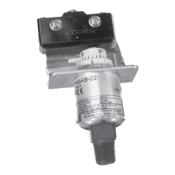
54 Series pressure switches are activated when a bellows, diaphragm or
piston sensor responds to a pressure change. This response, at a pre-deter-
mined set point, actuates one or two snap-acting switch(es), converting the
pressure signal into an electrical signal. Control set point may be varied by
turning the adjustment hex on "J" types or a reference adjustment dial on
"H" types. (See Adjustment -PART II).
PROOF PRESSURE* LIMITS STATED IN THE LITERATURE AND ON
NAMEPLATES MUST NEVER BE EXCEEDED, EVEN BY SURGES IN
THE SYSTEM. OCCASIONAL OPERATION OF UNIT UP TO PROOF
PRESSURE IS ACCEPTABLE (E.G., START-UP, TESTING). CONTINUOUS
OPERATION SHOULD NOT EXCEED THE DESIGNATED OVER RANGE PRESSURE.
*PROOF PRESSURE
THE MAXIMUM PRESSURE TO WHICH A PRESSURE SENSOR MAY BE OCCA-
SIONALLY SUBJECTED, WHICH CAUSES NO PERMANENT DAMAGE (E.G., START-
UP, TESTING). THE UNIT MAY REQUIRE RE-GAPPING.
THESE PRODUCTS DO NOT HAVE ANY FIELD REPLACEABLE PARTS.
Please refer to product bulletin for product specifications. Product bulletins
may be found at www.ueonline.com
Part I - Installation
MouNTING
LOCATE SWITCH WHERE VIBRATION, SHOCK, AND AMBIENT
TEMPERATURE FLUCTUATIONS ARE MINIMAL. TO AVOID DAMAGE TO
SWITCH, ALWAYS HOLD THE WRENCH ON THE WRENCH FLATS OR HEX
PORTION OF THE PRESSURE CONNECTION WHEN TIGHTENING.
The switch can be mounted in any position.
Enclosed Versions J54, J54A, and H54
Remove cover first by removing the one captive screw located on the front of
the cover.
54 Series
Pressure Switches
Types
Enclosed: J54, J54A, H54
Skeleton: J54S, J54AS, H54S
Tools Needed
Adjustable Wrench
Screwdriver
www.ueonline.com
U N I T E D E L E C T R I C
C O N T R O L S
Installation and Maintenance
Instructions
Pipe Mounting
Mount the switch directly to the line via the NPT pressure connection.
Vertical Surface Mount
Two holes for #10 screws are provided in the bracket plate.
Conduit Connection
A 7/8" diameter hole has been provided in the bracket plate for mounting a
conduit fitting.
Skeleton Versions J54S, J54AS H54S
Pipe Mounting
Mount the switch directly to the line via the NPT pressure connection.
Vertical Surface Mount
Two openings for #6 screws are provided in the rear of the bracket plate.
(See Figure 1).
WIRING
DISCONNECT ALL SUPPLY CIRCUITS BEFORE WIRING UNIT.
WIRE UNITS ACCORDING TO NATIONAL AND LOCAL ELECTRICAL
CODES. MAXIMUM RECOMMENDED WIRE SIZE IS 14 AWG. THE
RECOMMENDED TIGHTENING TORQUE FOR FIELD WIRING TERMINALS IS 7 TO
17 IN-LBS.
ELECTRICAL RATINGS STATED IN LITERATURE AND ON NAMEPLATES
MUST NEVER BE EXCEEDED - OVERLOAD ON A SWITCH CAN CAUSE
FAILURE ON THE FIRST CYCLE.
Bring wires up to the terminals from the rear, so that wires lay along insulator.
The three switch terminals are clearly labeled "common", "normally open" and
"normally closed". For optional switches supplied with leadwires, the following color
coding applies:
Common
Normally Open
Normally Closed
IMP54-05
IMP54-05
Figure 1
Manual Reset
(Option 1530)
SPDT
Violet
Blue
Black
Advertisement

Related Manuals for United Electric Controls 54 Series


Summary of Contents for United Electric Controls 54 Series
- Page 1 COMPATIBILITY BETWEEN THE PROCESS MEDIA AND THE SENSOR Two holes for #10 screws are provided in the bracket plate. AND WETTED PARTS. 54 Series pressure switches are activated when a bellows, diaphragm or Conduit Connection piston sensor responds to a pressure change. This response, at a pre-deter- A 7/8”...
- Page 2 High Set of Range Part II - Adjustments Using a 1/4” open end wrench, turn main adjustment screw counterclockwise Tools Needed (right) to lower set point or clockwise (left) to raise set point. Turning the 1/4” hex screw clockwise until “high set” switch transfers at the target pressure 1/4”...
- Page 3 Dimensions Dimensional drawings for all models may be found at www.ueonline.com. Type J54S models 22-28 Type J54S models 610-614 Type H54S models 22-28 Type J54 models 610-614 Type H54, J54 & J54A models 22-28 Type H54, J54, & J54A models 126-164 IMP54-05 www.ueonline.com...
- Page 4 RECOMMENDED PRACTICES AND WARNINGS United Electric Controls Company recommends careful consideration of the following factors when specifying and installing UE pressure and temperature units. Before installing a unit, the Installation and Maintenance instructions provided with unit must be read and understood.