Table of Contents
Advertisement
Quick Links
Installation, Operating and Servicing
Instructions
Please make a note of your product details for
future use:
Date Purchased:_________________________
Model Number:__________________________
Serial Number:__________________________
Dealer:_________________________________
________________________________
_______
A34/040 R4
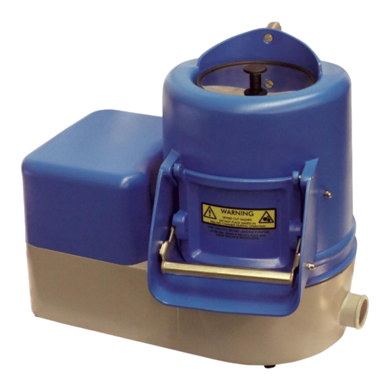
VQ3.5 & VQ7 – SERIES 1
ECN 4825 February 2021
Advertisement
Table of Contents

Related Manuals for IMC VQ3.5 1 Series


Summary of Contents for IMC VQ3.5 1 Series
- Page 1 VQ3.5 & VQ7 – SERIES 1 Installation, Operating and Servicing Instructions Please make a note of your product details for future use: Date Purchased:_________________________ Model Number:__________________________ Serial Number:__________________________ Dealer:_________________________________ ________________________________ _______ A34/040 R4 ECN 4825 February 2021...
-
Page 2: Table Of Contents
CONTENT DELIVERY ......................1 INTRODUCTION ....................2 YOUR PEELER ....................2 INSTALLATION ....................2 PROCEDURE ....................... 3 Work top models ..................... 3 Trolley installation ..................4 Pedestal installation ..................4 ELECTRICITY SUPPLY CONNECTION .............. 5 WATER SUPPLY ....................6 WASTE OUTLET CONNECTION ................. 6 Waste ejector (Optional Extra) ............... -
Page 3: Delivery
DELIVERY The packaged machine consists of: Peeler Unit Peeling plate Water supply pipe and 2 hose clips Rubber waste outlet hose Instruction Booklet If any accessories have been ordered they will be supplied in separate packages. Please notify both the carrier and the supplier within 24 hours of receipt if anything is missing or damaged. -
Page 4: Introduction
For the Installer: These Instructions contain important information designed to help the user obtain the maximum benefit from the investment in an IMC VQ Peeler. Please read them carefully before starting work, and consult with the supplier in the event of any queries. -
Page 5: Procedure
Procedure Work top models The VQ Range is designed to stand on a bench, table, or on a draining board. DO NOT mount or operate the unit in a sink. The peeled potatoes are commonly discharged into a sink and the waste sludge can be piped away separately, possibly using the waste ejector fitting. -
Page 6: Trolley Installation
Trolley installation The peeler can be mounted onto a trolley. If ordered, the trolley will be supplied in separate packaging. Mounting the peeler to the trolley is straightforward as follows: First it is advisable to remove the cylinder pot assembly and peeler plate before mounting on trolley. -
Page 7: Electricity Supply Connection
ELECTRICITY SUPPLY CONNECTION Before connecting, examine the rating plate attached to the machine to ensure that the characteristics shown are correct for the supply available. Any changes to the supply or fitting new mains cable runs should be carried out by a qualified electrician and in accordance with the IET Codes of Practice. -
Page 8: Water Supply
WATER SUPPLY Connect the water supply pipe to the hose tail located on the top of the cylinder. Fit the other end of the supply pipe to a cold water supply. PLEASE NOTE: these machines are fitted with an air-break to prevent back syphonage into the mains supply, but some local authorities may nevertheless require connection to a storage cistern rather than direct to the mains supply. -
Page 9: Waste Ejector Adjustments
The waste ejector fits onto the waste outlet boss in place of the waste outlet hose, as shown below. Ensure that the ejector body is vertical and secure in place with the jubilee clips supplied. The water supply to the ejector is via the hose tail on top of the waste ejector. -
Page 10: Operation
OPERATION Fit the peeler plate, ensuring that it is properly located on the drive shaft. Fit the cylinder and rotate into the required position. Lock into position with the two locking knobs. Measure out the potatoes into a container that holds a known measured weight, and check for any stones that could damage the abrasive. -
Page 11: Safety
SAFETY All VQ-Range machines are fitted with a number of safety features to prevent operator injury. Interrupt protection: If the electricity supply is interrupted the machine will not restart until the upper GREEN button on the on-of switch is pressed again. Cylinder interlock: If the cylinder is removed the motor will not start until it is replaced, and the green start button has been pressed. -
Page 12: Maintenance
MAINTENANCE Other than regular cleaning the VQ-Range of peelers require no maintenance by the end user. It is recommended that a Lincat approved engineer services the unit at least once a year. Details of Lincat Service Contracts are available on application. DO’S AND DON’TS Install on a level surface. -
Page 13: Wiring Diagram
WIRING DIAGRAM... -
Page 14: Exploded View: External Parts
EXPLODED VIEW: EXTERNAL PARTS VQ3.5 Item Part No Description Part No Description C72/202 M1 Motor Cover C72/202 M1 Motor Cover E72/208 Base Plate E72/208 Base Plate L72/023 Cylinder Locking Knob L72/023 Cylinder Locking Knob M72/001 Waste Outlet-Moulded M72/001 Waste Outlet-Moulded S72/012 VP Splash Cover S72/012... -
Page 15: Exploded View: Cylinder Assembly
EXPLODED VIEW: CYLINDER ASSEMBLY VQ3.5 Item Part No Description Part No Description A00/058 Nylon Shoulder Washer A00/058 Nylon Shoulder Washer A13/078 M5 Neoprene Door Gasket A13/078 M5 Neoprene Door Gasket D18/050 Screw M6 x 16 CSK SS D18/050 Screw M6 x 16 CSK SS D18/051 Screw M6 x 20 CSK SS D18/051... -
Page 16: Exploded View: Internal Parts
EXPLODED VIEW: INTERNAL PARTS BASE ASSEMBLY-UPPER VQ3.5 Item Part No Description Part No Description A08/295 Timer Label A08/295 Timer Label A11/219 Timer Rubber Washer A11/219 Timer Rubber Washer D20/043 Nut M6 Nyloc SS D20/043 Nut M6 Nyloc SS D21/034 Screw M3 x 16 Pan SS D21/034 Screw M3 x 16 Pan SS D23/044... - Page 17 BASE ASSEMBLY-LOWER VQ3.5 Item Part No Description Part No Description A05/007 V Belt A05/007 V Belt A13/048 Rubber Foot A13/048 Rubber Foot C07/004 M2 Driven Pulley-Machined C07/004 M2 Driven Pulley-Machined D19/037 Screw M6 x 10 Hex SS D19/037 Screw M6 x 10 Hex SS D19/115 Screw M6 x 30 Hex SS D19/115...
- Page 18 DRIVE ASSEMBLY VQ3.5 Item Part No Description Part No Description A01/032 Ball Bearing 47 x 20 x 14 A01/032 Ball Bearing 47 x 20 x 14 A02/037A Oil Seal 47 x 20 x 7 A02/037A Oil Seal 47 x 20 x 7 C07/004 M2 Driven Pulley-Machined C07/004 M2...
-
Page 19: Exploded Views: Motor Assembly & Electrical Box
EXPLODED VIEWS: MOTOR ASSEMBLY & ELECTRICAL BOX MOTOR ASSEMBLY VQ3.5 Item Part No Description Part No Description D08/096 Rubber Washer 25x5.5x4 D08/096 Rubber Washer 25x5.5x4 D19/032 Screw M5x12L Hex SS D19/032 Screw M5x12L Hex SS D19/143 Screw M4x20L Hex SS D19/143 Screw M4x20L Hex SS D25/021... - Page 20 ELECTRICAL BOX VQ3.5 Item Part No Description Part No Description D20/011 Nut M4 Full SS D20/011 Nut M4 Full SS D20/038 Nut M5 Full SS D20/038 Nut M5 Full SS D25/004 Washer M5 Shakeproof SS D25/004 Washer M5 Shakeproof SS D25/014 Washer M4 Plain SS D25/014...
-
Page 21: Guarantee
GUARANTEE This unit carries a comprehensive UK mainland 2 year warranty. The guarantee is in addition to, and does not diminish your statutory or legal rights. The guarantee does not cover: Accidental damage, misuse or use not in accordance with the manufacturer’s instructions. -
Page 22: Service Information
SERVICE INFORMATION For help with the installation, maintenance and use of your Lincat equipment, please contact our service department: UK: 01522 875520 For non-UK customers, please contact your local Lincat dealer All service work, other than routine cleaning should be carried out by one of our authorised service agents.
Need help?
Do you have a question about the VQ3.5 1 Series and is the answer not in the manual?
Questions and answers