Table of Contents
Advertisement
Available languages
Available languages
Quick Links
Bedienungsanleitung
Operation Manual
9500 einflügelig /
single-arm
9501 2 gekoppelte Flügel /
2 coupled arms
0 Digital Form-Hauptsignale
0 Semaphore home signals
DE
1. Wichtige Hinweise ..................................
2. Einleitung ................................................
3. Einbau ....................................................
4. Betrieb ....................................................
5. Wartung ..................................................
6. Fehlersuche und Abhilfe .........................
7. Gewährleistung ......................................
8. Technische Daten ...................................
Abbildungen und Tabellen ......................
EN
2
1. Important information ..............................
2
2. Introduction ..............................................
3
3. Mounting ..................................................
3
4. Operation .................................................
5
5. Maintenance ............................................
5
6. Trouble-shooting ......................................
6
7. Warranty ..................................................
6
8. Technical data .........................................
12
Figures and tables ...................................
9500
9501
DCC MM
AC
Rail
~
Com
Innovation,
die bewegt!
7
7
8
10
10
10
11
11
12
DC
=
Advertisement
Table of Contents

Related Manuals for Viessmann 9500


Summary of Contents for Viessmann 9500
-
Page 1: Table Of Contents
Bedienungsanleitung Operation Manual 9500 einflügelig / single-arm 9501 2 gekoppelte Flügel / 2 coupled arms 0 Digital Form-Hauptsignale 0 Semaphore home signals 9500 9501 1. Wichtige Hinweise ........1. Important information ......2. Einleitung ..........2. Introduction ..........3. Einbau ............ -
Page 2: Wichtige Hinweise
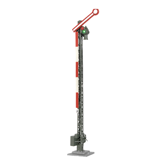
Decoder über Ausgänge zur Zugbeeinflussung. Zudem kann das Signal bei der Abwärtsbewegung realistisch nachwippen (s. Kapitel 4). Viessmann-Formsignale haben sehr filigrane Masten, die sich durch eine perfekte Vorbildtreue auszeichnen. Daher sollten Sie das Signal nie am Mast anfassen, sondern immer nur an der Bodenplatte (Abb. 1). Bei einem Ausbau aus der Modell- bahnplatte nicht oben ziehen, sondern die Elektronik unter der Platte greifen und nach oben hinausschieben! Hauptsignale stehen in Deutschland in der Regel in Fahrtrichtung gesehen rechts vom Gleis. -
Page 3: Einbau
Viele weitere Informationen über Signale finden Sie im Viessmann-Signalbuch, Art. 5299. 2.1 Ansteuerung im Analogbetrieb Das Viessmann Form-Hauptsignal können Sie auch in analog gesteuerten Modellbahnanlagen einsetzen. Sie können es sowohl mit Wechselstrom als auch mit Gleichstrom betreiben. Sobald Sie das Signal an Betriebsspannung anschließen, erkennt der integrierte Decoder automatisch, ob er analog oder digital angesteuert wird, und stellt den entsprechenden Betriebsmodus ein. - Page 4 Die Adresse des Signals wird in zwei CVs programmiert. In CV 1 steht das untere Byte (LSB) der Adresse, in CV 9 das obere Byte (MSB). Das Umrechnen der Adresse geschieht wie im Folgenden beschrieben. Wenn Sie eine Adresse zwischen 1 und 255 eingeben wollen, so schreiben Sie diesen Wert direkt in CV 1.
-
Page 5: Betrieb
Stellung bedeutet und führt diesen nach einer kurzen Kühlzeit (ca. 0,5 Sek.) aus. 4.2 Nachwippen bei Abwärtsbewegung Die Viessmann Flügelsignale, Art. 9500 und Art. 9501 ermöglichen den Bewegungsablauf, den man beim Vorbild auch oft vorfindet, nämlich das Nachwippen der Signalflügel bei abfallenden Flügeln. -
Page 6: Gewährleistung
Kaufdatum. Tritt in dieser Zeit ein Fehler auf und Sie finden die Fehlerursache nicht, nehmen Sie bitte Kontakt mit uns auf (service@viessmann-modell.com). Senden Sie uns den Artikel zur Kontrolle bzw. Reparatur bitte erst nach Rücksprache zu. Wird nach Überprüfung des Artikels ein Herstell- oder Materialfehler festgestellt, wird er kostenlos instandgesetzt oder ausgetauscht. -
Page 7: Important Information
At the end of the downward cycle the signal bounces up and down a number of times before settling into position (see chapter 4). Viessmann semaphores have finely detailed metal masts, which are very sensitive. Therefore you should never touch the masts but only the ground plate for installation and deinstallation (fig. 1). -
Page 8: Mounting
For further information concerning signals refer to the Viessmann signal book (item 5299). 2.1 Operation in analogue mode The Viessmann semaphore block signal can be used in analogue model train layouts. You may use AC or DC power supply for operation. - Page 9 Due to the low maximum load of the contacts and the short pulse length, it is important to use a relay (e. g. the Viessmann electronic relay, item 5552) as shown in fig.
-
Page 10: Operation
4.2 Signal bouncing during downward movement Viessmann semaphore signals, item 9500 and item 9501 allow the simulation of the typical bouncing effect for the down- ward movement of the semaphore arms. Regarding the prototype semaphore signals you can observe a little movement upward –... -
Page 11: Warranty
Should a fault occur during this period please contact our service department (service@viessmann-modell.com). Please send the item to the Viessmann service department for check and repair only after consultation. If we find a material or production fault to be the cause of the failure the item will be repaired free of charge or replaced. Expressively excluded... -
Page 12: Abbildungen Und Tabellen
1: Nachwippen wird am Ende einer Bewe- Bouncing 1: Signal arm bouncing enabled after a gung nach unten aktiviert. downward movement. 9500 (25) Höhe der ersten Wippbewegung. Height of the first bouncing movement. 9501 (20) 9500 (18) Höhe der zweiten Wippbewegung. - Page 13 Eingabewerte Erläuterungen / Hinweise Name der CV Remarks (Default) Name of CV value range EMK Messungen Anzahl von EMK Messungen, je Zyklus. Die Number of EMF measurements per ersten 2 Messungen werden automatisch EMF measurements cycle. The first two measurements will ignoriert.
- Page 14 Fig. 6 / red Méreta.: Anyag: Szín: RAL: Tervező: sszám: Fekete János 1.5:1 Dátum: 2012.02.22. év: grün / green 9500 0-Formsignal Rajzoló: Fekete János Név: Hauptsignal Dátum: ám: 2012.02.22. Universal Tasten - Stellpult Ellenőr: 9500/ Copy mszám: 9501 Dátum: 5547...
- Page 15 Abb. 7 Fig. 7 9500/ Adresse einstellen / Set address 9501 rotes Kabel verbinden / connect red cable grünes Kabel offen / green cable open grünes Kabel verbinden / connect green cable rotes Kabel offen / red cable open MM / DCC...
- Page 16 Abb. 8.1 Fig. 8.1 Anschluss nach Adressprogrammierung für invertierte Stellrichtung! Connection after programming the address for reverse switching direction! 4557 4557 9500/ 9501 Digital- Digital- / red / red zentrale zentrale Digital Digital command Command station Station gelb braun gelb...
Need help?
Do you have a question about the 9500 and is the answer not in the manual?
Questions and answers